Table of Contents
Advertisement
Quick Links
Operating Instructions
Functional Manual
Digital Interface Box
Commercial Use
ET-YFB100G
Model No.
Thank you for purchasing this Panasonic product.
■ This manual is intended for products manufactured from May 2013 and beyond.
■ Before operating this product, please read the instructions carefully and save this manual
for future use.
■ Before using this product, be sure to read "Read this first!" (
pages 3 to 8).
ENGLISH
TQBH0279-2
Advertisement
Table of Contents

Related Manuals for Panasonic ET-YFB100G


Summary of Contents for Panasonic ET-YFB100G
-
Page 1: Operating Instructions
Commercial Use ET-YFB100G Model No. Thank you for purchasing this Panasonic product. ■ This manual is intended for products manufactured from May 2013 and beyond. ■ Before operating this product, please read the instructions carefully and save this manual for future use. - Page 2 „ Trademarks • PJLink is a trademark or pending trademark in Japan, the United States, and other countries and regions. • HDMI, the HDMI Logo, and High-Definition Multimedia Interface are trademarks or registered trademarks of HDMI Licensing LLC in the United States and other countries. •...
-
Page 3: Read This First
Information Read this first! Read this first! WARNING: THIS APPARATUS MUST BE EARTHED. WARNING: TO REDUCE THE RISK OF FIRE OR ELECTRIC SHOCK, DONOT EXPOSE THIS PRODUCT TO RAIN OR MOISTURE. WARNING: 1. Remove the plug from the mains socket when this unit is not in use for a prolonged period of time. 2. - Page 4 To assure continued compliance, follow the attached installation instructions and use only shielded interface cables when connecting to computer and/or peripheral devices. Any changes or modifications not expressly approved by Panasonic Corp. of North America could void the user’s authority to operate this device. NOTIFICATION (Canada) This class B digital apparatus complies with Canadian ICES-003.
- Page 5 Read this first! IMPORTANT: THE MOULDED PLUG (U.K. only) FOR YOUR SAFETY, PLEASE READ THE FOLLOWING TEXT CAREFULLY. This appliance is supplied with a moulded three pin mains plug for your safety and convenience. A 13 amp fuse is fitted in this plug. Should the fuse need to be replaced, please ensure that the replacement fuse has a rating of 13 amps and that it is approved by ASTA or BSI to BS1362.
- Page 6 Read this first! WARNING: „ POWER The wall outlet or the circuit breaker shall be installed near the equipment and shall be easily accessible when problems occur. If the following problems occur, cut off the power supply immediately. Continued use of the device in these conditions will result in fire or electric shock. z If foreign objects or water get inside the device, cut off the power supply.
- Page 7 Read this first! WARNING: „ ON USE/INSTALLATION Do not place the device on soft materials such as carpets or sponge mats. Doing so will cause the device to overheat, which can cause burns, fire or damage to the device. Do not set up the device in humid or dusty places or in places where the device may come into contact with oily smoke or steam, ex.
- Page 8 Read this first! CAUTION: „ POWER When disconnecting the power cord, be sure to hold the power plug and power connector. If the power cord itself is pulled, the lead will become damaged, and fire, short-circuits or serious electric shocks will result. When not using the device for an extended period of time, disconnect the power plug from the wall outlet.
-
Page 9: Select The Input Signal
Features of this product Features of this product Quick Steps Quick Steps For details, refer to the corresponding pages. Easy setup and improved serviceability 1. Set up the interface box. ▶ Outputs the image, sound, ethernet, and page 15) serial control signals digitally by using one cable with CAT5e or higher grade to the projector... -
Page 10: Table Of Contents
Contents Be sure to read “Read this first!”. ( pages 3 to 8) [CLAMP POSITION] ........30 Important Information [DIGITAL CINEMA REALITY]......31 [POSITION] menu ........32 Read this first! ..........3 [SHIFT] ............32 Precautions for use ........11 [CLOCK PHASE] ..........32 Cautions when transporting ...... -
Page 11: Precautions For Use
Precautions for use Precautions for use Cautions when transporting z When transporting the interface box, avoid excessive vibration and impacts. Doing so may damage the internal parts and result in malfunctions. Cautions when installing ■ Do not set up the interface box outdoors. The interface box is designed for indoor use only. -
Page 12: Accessories
Precautions for use Accessories Make sure that the following accessories are provided with your interface box. Numbers enclosed in < > show the number of accessories. AC adaptor <1> Power cord <1> Power cord <1> (CF-AA6373AM1) (For USA) (For Europe) (K2CG3YY00152) (K2CM3YY00034) Power cord <1>... -
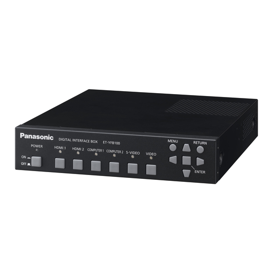
Page 13: About Your Interface Box
About your interface box About your interface box Main body ■ Front and lateral sides ▶ ■ Rear and bottom sides (1) Control panel ( page 13) (5) Mounting bracket screw hole for securing AC adaptor ( page 23) ... - Page 14 (5) <HDMI IN 1>/ <HDMI IN 2> terminal manufacturers has been made for the items This is a terminal to input HDMI signals. set by Panasonic Corporation, and not all the (6) <DC IN> terminal operations have been verified. For operation or Connects the supplied AC adaptor.
-
Page 15: Setting Up
Setting up Setting up Cautions when setting up the interface box ▶ z When mounting the interface box to a rack or a table underside, use the supplied rack/table underside mounting bracket or the rack mounting bracket. ▶ z Use a torque screwdriver or torque wrench to tighten bolts to their specified tightening torques. Do not use tools such as electric screwdrivers or impact screwdrivers. -
Page 16: Mounting To The Underside Of The Tabletop Of The Desk
Setting up 3) Fix to the rack by using the commercially available screws (4 pcs). *1: Use M5 or M6 screws for EIA standard rack. ▶ z Securely tighten the screws. Attention z During attachment, be careful that the interface box does not slip. z Be sure to fix the cables connected to the connecting terminals and the supplied AC adaptor nearby such as the supports of the rack to avoid the cable and AC adaptor weights directly applied to the interface box. -
Page 17: Mounting On The Desk Or The Shelf
Setting up Mounting on the desk or the shelf Mount the supplied set legs to the interface box. ▶ z Mount the legs to the set leg screw holes at the bottom side of the interface box with the supplied set leg screws (4 pcs). -
Page 18: Connections
Connections Connections Before connecting z Before connecting, carefully read the operating instructions of the devices to be connected. z Turn off the power of all devices before connecting cables. z Connect the cables by paying enough attention to the following points. If not, troubles may be led. •... -
Page 19: Connecting Example: Video And Audio Devices
Connections Connecting example: Video and audio devices Note z Use an HDMI High Speed cable that conforms to HDMI standards. If a cable not conforming the HDMI standard is used, the image may be interrupted or may not be displayed properly. z The interface box can connect to an external device, which has a DVI terminal, with the HDMI/DVI conversion cable. -
Page 20: Connecting Example: Computers
Connections Connecting example: Computers Control computer Computer Computer cable (commercially available) Control computer Attention z When connecting the interface box to a computer or an external device, use the power cord supplied with each device and commercially available shielded cables. z The positions of the <SERIAL IN>... -
Page 21: Connecting To The Digital Link Compatible Device
Connections Connecting to the DIGITAL LINK compatible device ■ Connections ▶ When connecting to the DIGITAL LINK When connecting to the projector that is not compatible projector DIGITAL LINK compatible The twisted-pair-cable receiver of other manufacturer DIGITAL LINK Names of the DIGITAL LINK compatible projector terminals may be different for each manufacturer. - Page 22 Panasonic website (http://panasonic.net/avc/projector/). Note that the verification for devices of other manufacturers has been made for the items set by Panasonic Corporation, and not all the operations have been verified. For operation or performance problems caused by the devices of other manufacturers, contact the respective manufacturers.
-
Page 23: Switching On/Off The Interface Box
Switching on/off the interface box Switching on/off the interface box Connecting the AC adaptor Confirm that the <POWER> button of the interface box is off, and then connect the power cord and the AC adaptor. For details of the AC adaptor and the power cord handling, refer to “Read this first!”( pages 3 to 8). -
Page 24: Switching On The Interface Box
Switching on/off the interface box ■ To remove the power cord 1) Confirm that the <POWER> button of the interface box is off, and remove from the power outlet by holding the power plug. 2) Remove the mounting bracket for securing AC adaptor. (i) Remove the mounting bracket screw for securing AC adaptor. -
Page 25: Checking The Image
Checking the image Checking the image Confirm the connections of the external device ( page 18) and the AC adaptor ( page 23) and then turn on the power ( page 24). Select the projecting image, and confirm that the selected image is projected from the ... -
Page 26: Remote Control Operation
Remote control operation Remote control operation The interface box can be operated by the remote control of the connected projector (only DIGITAL LINK compatible models). Some remote controls do not have some buttons and perform differently. z If the remote control signal receiver of the connected projector directly receives strong light, such as fluorescent light, the remote control may not operate properly. -
Page 27: Settings
On-screen menu navigation On-screen menu navigation The on-screen menu (Menu) is used to perform various settings and adjustments of the interface box. z If an item does not have any further information Navigating through the menu but only an item name, pressing the <ENTER> button displays the next screen, and detailed ■... -
Page 28: Main Menu
On-screen menu navigation Note Note z The remote control may not have the default z The factory default settings may vary depending on button, depending on the DIGITAL LINK compatible the picture mode. projector model connected to the interface box. z Sub-menu items and factory default settings are z To restore all settings to the factory default settings displayed differently depending on the selected... -
Page 29: [Input Select] Menu
[INPUT SELECT] menu [INPUT SELECT] menu Select [INPUT SELECT] from the main menu, and display the sub-menu. Refer to “Navigating through the menu” page 27) for the operation of the menu screen. Switching the input An input terminal for the image can be selected. z Press ▲▼... -
Page 30: [Picture] Menu
[PICTURE] menu [PICTURE] menu ■ When using <HDMI IN 1> Select [PICTURE] from the main menu, and terminal, or <HDMI IN 2> terminal select the item from the sub-menu. Refer to “Navigating through the menu” zDuring 480i, 576i, 480p, or 576p signal page 27) for the operation of the menu ... -
Page 31: [Digital Cinema Reality]
[PICTURE] menu [DIGITAL CINEMA REALITY] The vertical resolution can be improved when the function is used in the 2-2 and 2-3 pull down. Supported only when certain signals are input. 525i (480i), 625i (576i), 1125 (1080)/60i, 1125 (1080)/50i, S-video signal, and video signal 1) Press ▲▼... -
Page 32: [Position] Menu
[POSITION] menu [POSITION] menu [CLOCK PHASE] Select [POSITION] from the main menu, and select the item from the sub-menu. You can adjust to achieve an optimal image when Refer to “Navigating through the menu” there is a flickering image or smeared outlines. page 27) for the operation of the menu ... -
Page 33: [Aspect]
[POSITION] menu [ASPECT] Aspect mode Screen Input signal You can switch the aspect ratio of the image. 1) Press ▲▼ to select [ASPECT]. [NORMAL] 2) Press ◀▶ or the <ENTER> button. Outputs the full image z The [ASPECT] individual adjustment screen is without any hidden displayed. -
Page 34: [Input Resolution]
[POSITION] menu Aspect mode Screen Aspect mode Screen Input signal Input signal [V FIT] [FULL] Outputs the image with Outputs the image by the aspect ratio fixed using whole effective and by using whole area of the image effective area in the signals output from Projection screen vertical direction of the... -
Page 35: [Language] Menu
[LANGUAGE] menu [LANGUAGE] menu Select [LANGUAGE] from the main menu, and display the sub-menu. Refer to “Navigating through the menu” page 27) for the operation of the menu screen. Changing the display language You can select the language of the on-screen display. z Press ▲▼... -
Page 36: [Option] Menu
[OPTION] menu [OPTION] menu ■ [CLOSED CAPTION] Select [OPTION] from the main menu, and Sets whether a closed caption is displayed or not. select the item from the sub-menu. z The setting will change as follows each time you Refer to “Navigating through the menu” press the button. -
Page 37: [Sxga Mode]
[OPTION] menu [SXGA MODE] [NO SIGNAL SLEEP] Sets when the entire image is not displayed while Sets the time to stop the output from the <DIGITAL SXGA is input. LINK> terminal when the interface box detects that no Set it to [SXGA] normally. signal is input to the selected video input terminal. -
Page 38: [Audio Setting]
[OPTION] menu ■ [AUDIO OUT SELECT] [AUDIO SETTING] The sound output is set. Sets the details of the sound function. 4) Select [AUDIO OUT SELECT] in step 3). 1) Press ▲▼ to select [AUDIO SETTING]. 5) Press ◀▶ to switch [AUDIO OUT 2) Press the <ENTER>... -
Page 39: [Auto Setup]
[OPTION] menu [AUTO SETUP] [OUTPUT RESOLUTION] Sets the auto setup function. Set it to [AUTO] Sets the resolution of the image output from the normally. <DIGITAL LINK> terminal. 1) Press ▲▼ to select [AUTO SETUP]. 1) Press ▲▼ to select [OUTPUT RESOLUTION]. -
Page 40: [Status]
[OPTION] menu [STATUS] Displays the status of the interface box. 1) Press ▲▼ to select [STATUS]. 2) Press the <ENTER> button. z The [STATUS] screen is displayed. [SIGNAL] [NAME] Displays the input signal name. Displays the frequency of the [FREQUENCY] input signal. -
Page 41: Maintenance
Maintenance Maintenance After a long term usage, exhaust ports at upper and lateral sides of the interface box may be clogged with dust or trash. Clean the exhaust ports periodically. Wipe off dirt and dust on the outer case with a soft, dry cloth. z When removing dirt and dust, do not drop them inside the interface box. -
Page 42: Troubleshooting
Troubleshooting Troubleshooting Review the following points. For details, refer to the corresponding pages. Problems Points to be checked Page z Is the power plug firmly inserted into the outlet? ― z Is the power connector firmly inserted into the AC adaptor? ―... -
Page 43: Frequently Asked Questions
Frequently Asked Questions Frequently Asked Questions Check the following. Video is not projected across the entire screen when HDMI signals are input from a computer. Perform the following two steps. z Adjust the aspect ratio of screens output by a computer to suit projector pixels (aspect ratio). Example: If projector produces images of 1024 dots x 768 dots (4:3), set computer resolution to 800 x 600 (4:3). -
Page 44: Technical Information
Technical information Technical information PJLink protocol The <LAN> terminal of the interface box conforms with 100Base-T and 10Base-T. Signals are directly transferred to the using projector via DIGITAL LINK. Therefore, when PJLink protocol is used, follow the Operating Instructions of the using projector. The interface box cannot be controlled from this terminal. ■... -
Page 45: Serial In> Terminal
Technical information <SERIAL IN> terminal The <SERIAL IN> terminal of the interface box conforms with RS-232C. Signals are directly transferred to the using projector via DIGITAL LINK. For the detailed specifications of the control, see the Operating Instructions of the projector. ■... -
Page 46: Control Commands
Technical information ■ Communication conditions ▶ Signal level RS-232C-compliant Character length 8 bit Sync. method Asynchronous Stop bit 1 bit Baud rate 9 600 bps X parameter None Parity None S parameter None ■ Cable specification ▶ ▶ zWhen connected to a computer Interface box Computer (<SERIAL IN>... -
Page 47: Remote In> Terminal
Technical information <REMOTE IN> terminal Even when the signal from the remote control cannot reach the projector, the interface box can be remotely controlled (external control) from a control panel installed at a separate place when the <REMOTE IN> terminal of the interface box is used. -
Page 48: List Of Compatible Signals
Technical information List of compatible signals Image signals that are compatible with the input of the interface box are as shown in the following table. Scanning Plug and play frequency compatible Dot clock Signal name Resolution Mode Frequency Format display (Dots) Horizontal Vertical... -
Page 49: Corresponding 3D Signals List
Technical information Scanning Plug and play frequency compatible Dot clock Signal name Resolution Mode Frequency Format display (Dots) Horizontal Vertical COMPUTER HDMI (MHz) (kHz) (Hz) SXGA SXGA60 1 280 x 1 024 64.0 60.0 108.0 SXGA75 1 280 x 1 024 80.0 75.0 135.0... -
Page 50: Specifications
Specifications Specifications The following table describes the specifications of the interface box. Model No. ET-YFB100G Power supply DC 16 V (DC input terminal) 16 W (when the power is “off”: 0.2 W) Power consumption (including the supplied AC adaptor) Input AC 100 - 240 V, 0.8 - 1.5 A, 50 Hz/60 Hz... - Page 51 Specifications Model No. ET-YFB100G 2 set, high-density D-Sub 15 p (female) <COMPUTER 1 IN>/ RGB signals G: 0.7 V [p-p] 75 Ω (SYNC ON GREEN: 1.0 V [p-p] 75 Ω) <COMPUTER 2 IN> B,R: 0.7 V [p-p] 75 Ω terminal...
-
Page 52: Dimensions
Dimensions Dimensions ■ When mounting on the rack ▶ Units: mm Front 465.1 (18-5/16") (8.55) (11/32") Front 210 (8-9/32") 247.2 (9-23/32") (31/32") (482.2) (18-31/32") 52 - ENGLISH... - Page 53 Dimensions ■ When mounting to the underside of the tabletop of the desk ▶ ■ When mounting on the desk or the shelf ▶ ENGLISH - 53...
-
Page 54: Index
Index Index [RGB SYNC TERMINAL] ……………………… 36 RS-232C ………………………………………… 45 AC adaptor ……………………………………… 23 Accessories ……………………………………… 12 [ASPECT] ………………………………………… 33 Selecting the input signal ……………………… 25 <AUDIO IN> terminal …………………………… 14 <SERIAL IN> terminal ……………………… 14, 45 <AUDIO OUT> terminal ………………………… 14 Setting up …………………………………………... - Page 55 This symbol is only valid in the European Union. If you wish to discard this product, please contact your local authorities or dealer and ask for the correct method of disposal. Panasonic Corporation Web Site : http://panasonic.net/avc/projector/ © Panasonic Corporation 2012 W1012HK2093 -PJ...