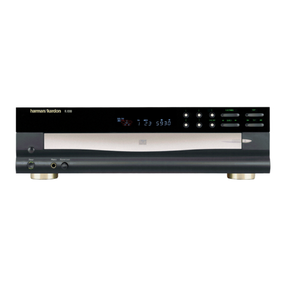
Harman Kardon FL8380 Service Manual
5 disc compact disc changer
Hide thumbs
Also See for FL8380:
- Technical manual (70 pages) ,
- Owner's manual (16 pages) ,
- Brochure & specs (40 pages)
Table of Contents
Advertisement
harman/kardon
5 Disc Compact Disc Changer
LASER BEAM SAFETY PRECAUTIONS .........2
OTHER PRECAUTIONS ................................ 3
SPECIFICATIONS .......................................... 4
FRONT PANEL CONTROLS........... ... .......... 6
REAR PANEL CONNECTIONS....................... 7
REMOTE CONTROL FUNCTIONS.................8
INSTALLATION/CONNECTIONS..................10
OPERATION................................................. 11
BASIC TROUBLESHOOTING ................. ..... 13
TEST PROCEDURE..................................... 14
CIRCUIT DESCRIPTION........... ... .............. 17
FL8380
Model
SERVICE MANUAL
250 Crossways Park Dr.
Woodbury, New York 11797
CONTENTS
BLOCK DIAGRAM .....................................21
GENERAL UNIT EXPLODED VIEW I, II ...... ..22
TECH TIP HKTT2003-06 ........................... 26
DETAILED TROUBLESHOOTING ............... 27
SEMICONDUCTOR IDENTIFICATION........... 33
PRINTED ClRCUlT BOARDS .............. ........ 59
ELECTRICAL PARTS LIST .......................... 61
MECHANICAL PARTS LIST ......................... 63
SCHEMATIC DIAGRAMS............................... 68
PACKAGE ...............................................72
harman/kardon, Inc.
Rev1 11/2003
Advertisement
Table of Contents
Troubleshooting

Related Manuals for Harman Kardon FL8380


Summary of Contents for Harman Kardon FL8380
-
Page 1: Table Of Contents
FL8380 Model 5 Disc Compact Disc Changer SERVICE MANUAL CONTENTS LASER BEAM SAFETY PRECAUTIONS ……...2 BLOCK DIAGRAM …………………….………...21 OTHER PRECAUTIONS …....…..… 3 GENERAL UNIT EXPLODED VIEW I, II .…..22 SPECIFICATIONS ......….…..4 TECH TIP HKTT2003-06 ……………………… 26 FRONT PANEL CONTROLS………..…..6 DETAILED TROUBLESHOOTING ……………... -
Page 2: Laser Beam Safety Precautions
FL8380 LASER BEAM SAFETY PRECAUTIONS CLASS 1 LASER PRODUCT CAUTION Invisible laser radiation when the unit is open. Do not stare into beam. CAUTION: USE OF ANY CONTROLS, ADJUSTMENT, OR PROCEDURES OTHER THAN THOSE SPECIFIED HEREIN MAY RESULT IN HAZARDOUS RADIATION EXPOSURE. -
Page 3: Other Precautions
FL8380 SAFETY PRECAUTIONS This symbol is intended to alert the user to the presence of uninsulated "dangerous voltage" within the product's enclosure that may be of sufficient magnitude to consti- tute a risk of electric shock to persons. This symbol is intended to alert the user to... -
Page 4: Specifications
Depth measurement includes knobs and buttons. Height measurement includes feet and chassis. All features and specifications are subject to change without notice. Harman Kardon is a registered trademark, and Power for the digital revolution is a trademark, of Harman Kardon, Inc. , HDCD ®... - Page 5 FL8380 GENERAL INFORMATION 1. Power Consumption Operating 18W; Standby <5W < 2. Power Super 230V AC 50Hz or 120V AC60Hz 3. Dimensions 440 x 130 x 386mm 4. Product Outlook Refer to attached diagram 5. Remote Unit harman/kardon remote code 6.
-
Page 6: Front Panel Controls
FL8380 Front Panel Controls FL 8380 PLAY/PAUSE STOP DISK SKIP ‹‹ SEARCH ›› Í‹‹ SKIP ››Í Power Phones Phones Level 1 Power Switch 6 Open/Close Button ! Disc Skip Button 2 Status Mode Indicator 7 Search Button @ Disc Select Button... -
Page 7: Rear Panel Connections
ON position. remote control output of another compatible Harman Kardon product. This will enable the ™ Coaxial Digital Output: Connect this remote control system to operate even when the front panel Remote Sensor $ is blocked. -
Page 8: Remote Control Functions
FL8380 Remote Control Functions a Disc-Select Buttons b Numeric Buttons c Clear Button d Search Buttons DISC NO. POWER e Skip Buttons f Stop Button g Play Button TRACK NO. DISC h Random Button SKIP i Pause Button – REPEAT... - Page 9 FL8380 Remote Control Functions a Disc-Select Buttons: Press one of these j Program Button: This button is used to buttons to select the disc in a specific position program the playback of a disc in a particular in the CD drawer.
-
Page 10: Installation/Connections
This jack may also be connected to the IR-Output jack of another compatible If your system includes an optional external Harman Kardon component or a compatible IR- digital-to-analog converter, or if you are using a system-remote product. receiver or other processor that has the capabil-... -
Page 11: Operation
FL8380 Operation Loading Discs Note that each disc position has a number of tracks on the disc will light at the far right embossed in the plastic tray. This corresponds to side of the display. To load a disc, first turn the FL 8380 on, using... -
Page 12: Normal Play
FL8380 Operation Normal Play Random 1: To play all the tracks on a disc in Its high-quality digital-to-analog circuitry pro- random order, press the Random button vides enhanced playback from all standard CD ONCE so that the indicator lights. The audio discs. -
Page 13: Basic Troubleshooting
FL8380 Troubleshooting Guide SYMPTOM POSSIBLE CAUSE SOLUTION No lights on front panel • No AC power • Make certain that the AC power cord is plugged into a live outlet Remote does not appear to operate • Main Power Switch turned off •... -
Page 14: Test Procedure
FL8380 Audio Characteristics Test Procedure Test Equipment 1. 3346 CD Player Evaluating Filter x 2 (NF Electronic Instrument) 2. VP7722 Panasonic Audio Analyzer 3. Sony YEDS18 Test CD disc Procedure Equipment Setup 1. The audio output of the CD player under test is connected to the CD filter L &... - Page 15 FL8380 Signal to Noise Ratio 1. Set the mode of the filter to ‘ S/N’ mode 2. Play track 2 of the test disc 3. The unit of the audio analyzer is set to dB mode 4. Press the S/N key on the control panel of the audio analyzer 5.
- Page 16 FL8380 FL8380 Preliminary Production Specification Test Disc Specification Typical Limit Black Dot TCD 725B 1000um 600um Interruption MCD-131 900um 600um Finger print 75um 65um Vertical Deviation MCD-151 0.92mm 0.92mm Eccentricity TCD 712 140um 140um 8cm test disc TCD 783 Last Track...
-
Page 17: Circuit Description
FL8380 FUNCTION DESCRIPTION Tracking System To Focus System REF1 REF2 Subtraction GCTRL TBAL GCTRL TEOUT TBAL PDIC The tracking error output of E and F is given to Pin 25 (TEOUT). C8 is required for oscillation-proof. R10 is chosen such that TEOUT of Pin 25 become 1.4Vp-p. - Page 18 FL8380 Focus System Subtraction GCTRL FBAL GCTRL PDIC FEOUT FBAL The focus error output of A, B, C and D are given to Pin 27. C4 is required for oscillation- proof. R7 is set such that FEOUT of Pin 27 becomes 1.46 Vp-p.
- Page 19 FL8380 RF, EQ, AGC NRFDET RFOUT DETECTION DETECTION GCTRL GCTRL The signals A, B, C and D input from PDIC are composed into the RF signal by the RF Addition Amp, then output from RFOUT of Pin 5. This Amp is designed so that RFOUT is about 0.5 Vp-p for normal CD disc (about 0.4 Vp-p for CDR and 0.12 Vp-p for CDRW).
- Page 20 FL8380 LDON LASER UNIT 170mV The laser diode has large negative temperature characteristic in its optical output when driven with a constant current on laser diode. Therefore, the output on processing monitor photo diode, must be a controlled current for getting regular output power, thus the APC (Auto Power Control) circuit is composed.
-
Page 22: General Unit Exploded View I, Ii
FL8380... - Page 23 FL8380 5-CD MECHANISM 9600-505007-001...
- Page 24 FL8380...
- Page 25 FL8380 5-CD MECHANISM 9600-505007-001...
-
Page 26: Tech Tip Hktt2003-06
TECH TIPS harman/kardon Troubleshooting tips and solutions to common service problems For models: FL8350/FL8550/FL8380 TIP# HKTT2003-06 Complaint: Unit Will Not Play or Recognize a Disc, “Skipping”. Possible Problem: Misalignment of the top cover and rear panel. To test, attempt to play the unit with the top cover OFF. If symptoms persist, troubleshoot further. If the unit will play with the cover OFF, the problem is caused by a misalignment of the top cover and the rear panel. -
Page 27: Detailed Troubleshooting
FL8380... - Page 28 FL8380...
- Page 29 FL8380...
- Page 30 FL8380...
- Page 31 FL8380...
- Page 32 FL8380...
-
Page 33: Semiconductor Identification
FL8380 MN662790RSA1 Signal Processing LSI for CD Players Overview The MN662790RSA is a CD signal processing LSI that, (Audio circuits) on a single chip, combines optics servos for the CD player Digital filter using 8-fold oversampling (focus, tracking, and traverse servos), digital signal... - Page 34 FL8380 MN662790RAS1 Pin Assignment BYTCK/TVSTOP LDON CLDCK FCLK RFDET IPFLAG TRCRS FLAG CLVS VDET RFENV DEMPH FLAG6/RESY IOSEL TBAL TEST FBAL OUTL OUTR KICK RSEL CSEL PSEL MSEL SSEL (TOP VIEW) QFS080-P-1414...
- Page 35 FL8380 MN662790RAS1 Block Diagram OUTR LRCKIN/MSEL BCLKIN/SSEL SRDATEIN/PSEL OUTL IOSEL CLVS BLKCK CLDCK FLAG SBCK IPFLAG SUBC DEMPH FLAG6/RESY SSEL SQCK SUBQ PLLF LRCK PLLF2 SRDATA DSLF BCLK DMUTE RSEL PSEL KICK MCLK BYTCK/TRVSTOP MDATA CK384/EFM VCOF2 VCOF TBAL FBAL...
- Page 36 FL8380 MN662790RAS1 Pin Descriptions Pin No. Symbol Function Description BCLK SRDATA bit clock output. LRCK Left/right channel discrimination signal output. SRDATA Serial data output. Power supply for digital circuits. Ground for digital circuits. Digital audio interface output signal. MCLK Microcomputer command clock input. (Data is latched at rising edge.) MDATA Microcomputer command data input.
- Page 37 FL8380 MN662790RAS1 Pin Descriptions (continued) Pin No. Symbol Function Description Tracking error signal input. (analog input) RFENV RF envelope signal input. (analog input) VDET Vibration detection signal input. "H" level: vibration detected. Offtrack signal input. "H" level: offtrack. TRCRS Track cross signal input.
- Page 38 FL8380 MN662790RAS1 Pin Descriptions (continued) Pin No. Symbol Function Description CLVS Spindle servo phase synchronization signal output. "H" level: CLV. "L" level: rough servo. During default operation, subcode CRC check result output. "H" level: OK. "L" level: no good. During command execution, pulse output for external track counter.
- Page 39 FL8380 FL8380 AN8849SB Head amplifier IC for CD-ROM drive (for 24 times speed or more) Overview Unit: mm The AN8849SB is a head amplifier IC for +0.10 15.2±0.3 –0.05 digital servo. It can configure an efficient CD-ROM system in combination with the MN662752, and...
- Page 40 FL8380 AN8849SB Block Diagram 3TOUT LDON GCTRL FBAL CROSS NRFDET CCRS CAGC TEOUT TBAL EQSW RFOUT...
- Page 41 FL8380 AN8849SB Pin Descriptions Pin No. Description Pin No. Description APC amp. input pin GND pin APC amp. output pin APC & masking control pin RF addition amp. inverted input pin output pin REF1 Power supply pin 1 CROSS output pin RF addition amp.
- Page 42 FL8380 AN8849SB Electrical Characteristics at T 25 C Parameter Symbol Conditions Unit Current consumption with no load 1 5 V, V 3.3 V 28.4 40.6 52.8 TOTAL1 0.75 V EQSW REF2 Current consumption with no load 2 5 V, V 3.3 V...
- Page 43 FL8380 AN8849SB Electrical Characteristics at T 25 C (continude) Parameter Symbol Conditions Unit Tracking error amp. (continued) Tracking error amp. 5 V, V 3.3 V 8.35 6.35 4.35 balance relative output 2 H 0.5 V REF2 Tracking error amp. 5 V, V 3.3 V...
- Page 44 FL8380 AN8849SB Electrical Characteristics at T 25 C (continued) Parameter Symbol Conditions Unit NRF detection NRF det. detection level 500 kHz, V 0.75 V 137 mV[p-p] RDA1 REF2 NRF det. high-level output 500 kHz, V 0.75 V RDAH REF2 voltage NRF det.
- Page 45 FL8380 AN8814SB 4-channel driver IC for optical disk drive Overview Unit: mm The AN8814SB is a BTL system 4-channel 18.4±0.2 (5.15) driver and is encapsulated in the SMD package (4.8) which excels in heat radiation characteristic. (1.315) Features Wide output dynamic range regardless of refer-...
- Page 46 FL8380 AN8814SB Pin Descriptions Pin No. Description Pin No. Description Motor driver-2 reverse rotation output pin Base control pin for an external transistor of 3.3 V regulator Motor driver-2 forward rotation output pin 3.3 V regulator output monitor pin Motor driver-1 reverse rotation output pin N.C.
- Page 47 FL8380 AN8814SB Electrical Characteristics at T 25 C Parameter Symbol Conditions Unit Current consumption with no load Motor driver 1 to motor driver 4 Input offset voltage 5 V, V 0 V, to R k , R to R Output offset voltage...
-
Page 48: Usage Notes
FL8380 AN8814SB Electrical Characteristics at T 25 C (continued) Design reference data Note) The characteristics listed below are theoretical values based on the IC design and are not guaranteed. Parameter Symbol Conditions Unit Thermal protection circuit Operating temperature equilibrium value... - Page 49 FL8380 ® ® PCM1732 For most current data sheet and other product information, visit www.burr-brown.com 24-Bit, 96kHz, Stereo Audio DIGITAL-TO-ANALOG CONVERTER ® With HDCD Decoder FEATURES DESCRIPTION ENHANCED MULTI-LEVEL The PCM1732 is designed for mid- to high-grade digital audio applications which achieve 96kHz sam-...
- Page 50 FL8380 SPECIFICATIONS 24-Bit Data Performance All specifications at +25 C, +V = +V = +5V, f = 44.1kHz, and SYSCLK = 384f , unless otherwise noted. PCM1732 PARAMETER CONDITIONS UNITS Bits RESOLUTION DATA FORMAT Audio Data Interface Format Standard/I Data Bit Length...
- Page 51 FL8380 SPECIFICATIONS 16-Bit Data Performance All specifications at +25 C, +V = +V = +5V, f = 44.1kHz, and SYSCLK = 384f , unless otherwise noted. For discussion of HDCD scaling options, see the Applications Considerations section of this data sheet.
- Page 52 FL8380 PIN CONFIGURATION PIN ASSIGNMENTS Top View SO-28 NAME DESCRIPTION LRCIN Left and Right Clock Input. This clock is equal to the sampling rate, f Serial Audio Data Input LRCIN ML/I BCKIN Bit Clock Input for Serial Audio Data CLKO Buffered System Clock Output.
- Page 53 FL8380 Motor driver ICs Reversible motor driver BA6209 / BA6209N The BA6209 and BA6209N are reversible-motor drivers suitable for brush motors. Two logic inputs allow three output modes : forward, reverse, and braking. The motor revolving speed can be set arbitrarily by controlling the voltage applied...
- Page 54 FL8380 Motor driver IC BA6209 / BA6209N FMeasurement circuit...
- Page 55 FL8380 MCU Pin Arrangement and Functions Pin Arrangement VFD.DO MCLK VFD.DI MDATA VFD.CLK VFD.LAT SENSE FLOCK TLOCK SQCK REMOTE SUBQ DMUTE STAT XRST PUSW CDRW Figure 1.2 Pin Arrangement...
- Page 56 FL8380 Internal Block Diagram Figure 1.1 shows a block diagram. H8/300L Data bus (lower) /FTID /FTIC /FTIB /FTIA /FTOB /FTOA /TMOW /FTCI /PWM /IRQ /IRQ /IRQ /TRGV /SCK /TMOV Timer A SCI1 /RXD /TMCIV /TXD /TMRIV Timer B1 SCI3 /SCK...
- Page 57 FL8380 Pin Functions Pin Name Description No connection No connection AVSS Connected 0V TEST Connected 0V No connection Connected 5V MCU ground line; connected to 0V OSC1 10MHz crystal input OSC2 10MHz crystal input MCU reset line; 0V = reset; 5V = normal operation...
- Page 58 FL8380 No connection No connection No connection No connection VFD.DO Display driver status serial data VFD.DI Display driver command serial data VFD.CLK Display driver command serial clock VFD.LAT Display driver command serial latch No connection No connection CD DSP internal status for auto-adjustment...
-
Page 59: Printed Clrcult Boards
FL8380... - Page 60 FL8380...
-
Page 61: Electrical Parts List
FL8380 FL8380 Electrical Parts List MAIN BOARD ASSY Reference Part number RESISTOR R13, R64 1001-000312-000 CARBON FILM RESISTOR 10 OHM 1/2W +-5% 1001-000314-020 CARBON FILM RESISTOR 10 OHM 1/4W +-5% AXIAL TAPE 1001-000316-020 CARBON FILM RESISTOR 10 OHM 1/6W +-5% AXIAL TAPE... - Page 62 FL8380 FL8380 Electrical Parts List (Cont'd) C67, C70 1101-102062-000 POLYESTER/MYLAR CAP. 0.001UF/100V +-5% 1101-103062-000 POLYESTER/MYLAR CAP. 0.01UF/100V +-5% C40, C133, C135 1101-222062-000 POLYESTER/MYLAR CAP. 2200PF/100V +-5% C29, C39 1101-273062-000 POLYSTER CAP. 0.027UF/100V +-5% C128, C129 1101-332062-000 POLYESTER/MYLAR CAP. 0.0033UF/100V +-5% 1101-562062-000 POLYESTER/MYLAR CAP.
-
Page 63: Mechanical Parts List
FL8380 FL8380 Electrical Parts List (Cont'd) 4162-090002-300 I.C. BA6209 SIL MOTOR DRIVER (ROHM) 4162-090002-301 IC BA6209N SIL MOTOR DRIVER WITHOUT HEAT SINK ROHM 4166-279122-000 I.C. MN662790RSA1 QFP TYPE 80PIN DSP (PANASONIC) 4174-040102-910 I.C. SN74HCU04 SOP (T.I.) 4178-050310-000 I.C. LM78L05 TO92... - Page 64 SCREW M3X8 P.T.P. B/H 7003-016002-112 SCREW M3X16 PTP B/H ZN 7004-010010-112 SCREW M4X10 B/H 7104-010010-022 WASHER M4X10X1MM 7104-010010-022 WASHER M4X10X1MM 7104-010010-022 WASHER M4X10X1MM 8583-801010-301 FL8380 FRONT PANEL (HARMAN KARDON FL8380) REV A 6083-810001-000-01 HARMAN KARDON FL8380 FRONT PANEL (W SILKSCREEN)
- Page 65 FL8380 Mechanical Parts List (Cont'd) FL8380 6083-810004-000-01 BUTTON DISC W PAINTED 6083-810006-000-01 OPEN/CLOSE KNOB W/PAINTED 6083-810007-000-01 BUTTON PLAY, PAINTED 6083-810009-000-01 HK-FP105.1 PAINTED CAP BUTTON DIMMER FOR FL8380 6083-810011-000 FILTER, FL (PVC 0.5t) 6083-810013-000-01 KNOB, VR, PAINTED 6083-810014-000-01 BUTTON STANDBY, PAINTED 6083-810015-000 INDICATOR, STANDBY SAN(MILKY)
- Page 66 FL8380 FL8380 Mechanical Parts List (Cont'd) 2500-021301-050 2PIN 130MM 1CONN CABLE AWG#28 UL1571 2mmP 6005-050018-000 MOTOR PULLEY FF130SH11340-2684A MOTOR FF-130SH-11340-02684A (MABUCHI) 8500-055040-100 MOTOR BRACKET SUB-ASSY 6505-050004-004 MOTOR BRACKET 6600-020201-001 5CD SHAFT, GEAR ROTARY 8500-055050-100 BRACKET ROLLER ASSY 6005-050017-000 ROLLER 6505-050005-001...
- Page 67 FL8380 FL8380 Mechanical Parts List (Cont'd) 9400-501000-701 5CD TURN TABLE BOARD ASSY REV A 2300-002000-001 STRAIGHT CONN WAFER 2PIN 2MMP JST 2300-006000-000 STRAIGHT CONN. WAFER 6 PINS 2mmP 2501-062801-150 6PIN 280MM 2CONN RIBBON CABLE AWG#28 2MMP 4841-010700-006 5CD TURN TABLE REV F...
-
Page 72: Package
FL8380 Ref# Part Number Description 5013-835001-001-10 Outer Carton 5000-835001-001 End Packing Foam FL 8380 FL8380 Unit 9805-020000-071 FL8380 Remote Control 2617-210004-001 Cable 2611-310009-000 RCA Cable Warranty Sheet Instruction Sheet 5100-838000-000 Owner’s Manual...