D-Link DES-3550 Manual
Managed 48-port 10/100mbps and 2ge ports layer 2 ethernet switch
Hide thumbs
Also See for DES-3550:
- Command line interface reference manual (323 pages) ,
- User manual (192 pages) ,
- User manual (328 pages)

Related Manuals for D-Link DES-3550


Summary of Contents for D-Link DES-3550
-
Page 1: Ethernet Switch
D-Link ™ DES-3550 Managed 48-port 10/100Mbps and 2GE ports Layer 2 Ethernet Switch Release II Manual Second Edition (June 2004) Printed In Taiwan RECYCLABLE... - Page 2 Microsoft Corporation. Other trademarks and trade names may be used in this document to refer to either the entities claiming the marks and names or their products. D-Link Computer Corporation disclaims any proprietary interest in trademarks and trade names other than its own.
-
Page 3: Table Of Contents
DES-3550 Fast Ethernet Layer 2 Switch Table of Contents Preface..................................... viii Intended Readers ................................ix Typographical Conventions................................ix Notes, Notices, and Cautions..............................ix Safety Instructions................................x Safety Cautions....................................x General Precautions for Rack-Mountable Products .......................... xi Protecting Against Electrostatic Discharge............................xii Introduction....................................1 Fast Ethernet ...................................... 1 Gigabit Ethernet Technology................................ - Page 4 DES-3550 Fast Ethernet Layer 2 Switch Password Protection..................................16 SNMP Settings ....................................16 Traps ..................................17 MIBs ..................................17 IP Address Assignment..................................17 Connecting Devices to the Switch ..............................19 Introduction to Web-based Switch Configuration........................20 Introduction ..................................20 Login to Web Manager ..................................20 Web-based User Interface................................
- Page 5 Static Multicast Forwarding................................54 Multicast Port Filtering..................................56 VLANs ....................................57 Understanding IEEE 802.1p Priority ............................... 57 VLAN Description................................... 57 Notes About VLANs on the DES-3550 ........................58 IEEE 802.1Q VLANs ..................................58 802.1Q VLAN Tags..............................59 Port VLAN ID .................................60 Tagging and Untagging............................60 Ingress Filtering ...............................61...
- Page 6 DES-3550 Fast Ethernet Layer 2 Switch Port-Based Network Access Control ............................... 99 MAC-Based Network Access Control ............................101 Configure Authenticator ................................101 PAE System Control..................................104 Port Capability ...............................104 Initializing Ports for Port Based 802.1x.........................106 Initializing Ports for MAC Based 802.1x ......................108 Reauthenticate Port(s) for Port Based 802.1x ......................108...
- Page 7 DES-3550 Fast Ethernet Layer 2 Switch Monitoring ...................................142 Port Utilization ................................142 CPU Utilization ................................143 Packets.....................................144 Received(RX) ....................................144 UMB Cast(RX)....................................146 Transmitted (TX) ................................... 148 Errors....................................150 Received (RX) ....................................151 Transmitted (TX) ................................... 153 Size ....................................155 MAC Address..................................157 Switch History.................................159 IGMP Snooping Group ..............................160...
- Page 8 DES-3550 Fast Ethernet Layer 2 Switch Group Icon ................................180 Commander Switch Icon............................181 Member Switch Icon..............................182 Candidate Switch Icon ............................183 Menu Bar ....................................... 184 Group ..................................185 Device ..................................185 View..................................185 Firmware Upgrade................................185 Configuration File Backup/Restore ..........................186 Appendix A ..................................187 Appendix B ..................................189 Cables and Connectors............................189...
- Page 9 DES-3550 Fast Ethernet Layer 2 Switch...
-
Page 10: Preface
DES-3550 Fast Ethernet Layer 2 Switch Preface The DES-3550 Manual is divided into sections that describe the system installation and operating instructions with examples. Section 1, “Introduction”– Describes the Switch and its features. Section 2, “Installation” – Helps you get started with the basic installation of the Switch and also describes the front panel, rear panel, side panels, and LED indicators of the Switch. -
Page 11: Intended Readers
DES-3550 Fast Ethernet Layer 2 Switch Intended Readers The DES-3550 Manual contains information for setup and management of the Switch. This manual is intended for network managers familiar with network management concepts and terminology. Typographical Conventions Convention Description In a command line, square brackets indicate an optional entry. For example: [copy filename] means that optionally you can type copy followed by the name of the file. -
Page 12: Safety Instructions
DES-3550 Fast Ethernet Layer 2 Switch Safety Instructions Use the following safety guidelines to ensure your own personal safety and to help protect your system from potential damage. Throughout this safety section, the caution icon ( ) is used to indicate cautions and precautions that you need to review and follow. -
Page 13: General Precautions For Rack-Mountable Products
DES-3550 Fast Ethernet Layer 2 Switch remove the grounding prong from a cable. If you must use an extension cable, use a 3-wire cable with properly grounded plugs. • Observe extension cable and power strip ratings. Make sure that the total ampere rating of all products plugged into the extension cable or power strip does not exceed 80 percent of the ampere ratings limit for the extension cable or power strip. -
Page 14: Protecting Against Electrostatic Discharge
DES-3550 Fast Ethernet Layer 2 Switch • Do not step on or stand on any component when servicing other components in a rack. NOTE: A qualified electrician must perform all connections to DC power and to safety grounds. All electrical wiring must comply with applicable local or national codes and practices. -
Page 15: Introduction
DES-3550 Fast Ethernet Layer 2 Switch Section 1 Introduction Ethernet Technology Switch Description Features Ports Front-Panel Components Side Panel Description Rear Panel Description Gigabit Combo Ports Ethernet Technology Fast Ethernet Technology Fast Ethernet The growing importance of LANs and the increasing complexity of desktop computing applications are fueling the need for high performance networks. -
Page 16: Switching Technology
Switch Description The DES-3550 is equipped with unshielded twisted-pair (UTP) cable ports providing dedicated 10 or 100 Mbps bandwidth. The Switch has 48 UTP ports and Auto MDI-X/MDI-II convertible ports that can be used for uplinking to another switch. -
Page 17: Ports
DES-3550 Fast Ethernet Layer 2 Switch Dual Image Firmware • Simple Network Time Protocol support • MAC Notification support • Asymmetric VLAN support • System and Port Utilization support • System Log Support • High performance switching engine performs forwarding and filtering at full wire speed, maximum 14, 881 •... -
Page 18: Front-Panel Components
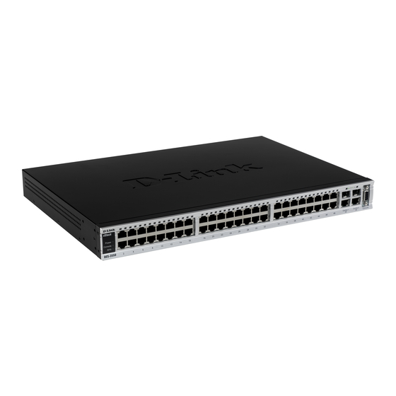
The front panel of the Switch consists of LED indicators for power and for each 10/100 Mbps twisted-pair ports, and two 1000BASE-T Mini-GBIC ports. DES-3550 Figure 1- 1. Front Panel View of the DES-3550 as shipped Comprehensive LED indicators display the status of the Switch and the network. LED Indicators The Switch supports LED indicators for Power, Console, RPS and Port LEDs. -
Page 19: Rear Panel Description
DES-3550 Fast Ethernet Layer 2 Switch Port LEDs One row of LEDs for each port is located above the ports on the front panel. The first LED is for the top port and the second one is for the bottom ports. These port LEDs will light two different colors for 10M and 100M. -
Page 20: Gigabit Combo Ports
DES-3550 Fast Ethernet Layer 2 Switch Figure 1- 4. Side Panels Gigabit Combo Ports In addition to the 48 10/100 Mbps ports, the Switch features two Gigabit Ethernet Combo ports. These two ports are 1000BASE-T copper ports (provided) and Mini-GBIC ports (optional). See the diagram below to view the two Mini-GBIC port modules being plugged into the Switch. -
Page 21: Installation
DES-3550 Fast Ethernet Layer 2 Switch Figure 1- 6. Installing the Mini-GBIC Module SECTION 2 Installation Package Contents Before You Connect to the Network Installing the Switch Without the Rack Rack Installation Power On Package Contents Open the shipping carton of the Switch and carefully unpack its contents. The carton should contain the following items:... -
Page 22: Before You Connect To The Network
RS-232 console cable • If any item is found missing or damaged, please contact your local D-Link Reseller for replacement. Before You Connect to the Network The site where you install the Switch may greatly affect its performance. Please follow these guidelines for setting up the Switch. -
Page 23: Installing The Switch In A Rack
DES-3550 Fast Ethernet Layer 2 Switch Installing the Switch in a Rack The Switch can be mounted in a standard 19" rack. Use the following diagrams to guide you. Figure 2- 2. Fasten mounting brackets to Switch Fasten the mounting brackets to the Switch using the screws provided. With the brackets attached securely, you can mount the Switch in a standard rack as shown in Figure 2-3 on the following page. -
Page 24: Power On
DES-3550 Fast Ethernet Layer 2 Switch Power On Plug one end of the AC power cord into the power connector of the Switch and the other end into the local power source outlet. After the Switch is powered on, the LED indicators will momentarily blink. This blinking of the LED indicators represents a reset of the system. -
Page 25: Switch To Hub Or Switch
DES-3550 Fast Ethernet Layer 2 Switch Figure 3- 1. Switch connected to an end node The Link/Act LEDs for each UTP port will light green or amber when the link is valid. A blinking LED indicates packet activity on that port. -
Page 26: Introduction To Switch Management
DES-3550 Fast Ethernet Layer 2 Switch Figure 3- 3. Uplink Connection to a server. Section 4 Introduction To Switch Management Management Options Web-based Management Interface SNMP-Based Management Managing User Accounts Command Line Console Interface Through The Serial Port Connecting the Console Port (RS-232 DCE) -
Page 27: Management Options
DES-3550 Fast Ethernet Layer 2 Switch Management Options This system may be managed out-of-band through the console port on the front panel or in-band using Telnet. The user may also choose the web-based management, accessible through a web browser. Web-based Management Interface After you have successfully installed the Switch, you can configure the Switch, monitor the LED panel, and display statistics graphically using a web browser, such as Netscape Navigator (version 6.2 and higher) or Microsoft®... -
Page 28: First Time Connecting To The Switch
12. Enter the commands to complete your desired tasks. Many commands require administrator-level access privileges. Read the next section for more information on setting up user accounts. See the DES-3550 Command Line Interface Reference Manual on the documentation CD for a list of all commands and additional information on using the CLI. - Page 29 Figure 4- 2. Initial screen, first time connecting to the Switch Press Enter in both the Username and Password fields. You will be given access to the command prompt DES-3550:4# shown below: There is no initial username or password. Leave the Username and Password fields blank.
-
Page 30: Password Protection
Password Protection The DES-3550 does not have a default user name and password. One of the first tasks when settings up the Switch is to create user accounts. If you log in using a predefined administrator-level user name, you have privileged access to the Switch's management software. -
Page 31: Traps
The DES-3550 supports SNMP versions 1, 2c, and 3. You can specify which version of SNMP you want to use to monitor and control the Switch. The three versions of SNMP vary in the level of security provided between the management station and the network device. - Page 32 DES-3550 Fast Ethernet Layer 2 Switch The Switch is also assigned a unique MAC address by the factory. This MAC address cannot be changed, and can be found by entering the command "show switch" into the command line interface, as shown below.
-
Page 33: Connecting Devices To The Switch
DES-3550 Fast Ethernet Layer 2 Switch Figure 4- 5. Assigning the Switch an IP Address In the above example, the Switch was assigned an IP address of 10.53.13.144 with a subnet mask of 255.0.0.0. The system message Success indicates that the command was executed successfully. The Switch can now be configured and managed via Telnet and the CLI or via the Web-based management. -
Page 34: Introduction To Web-Based Switch Configuration
IGMP Snooping Status Introduction All software functions of the DES-3550 can be managed, configured and monitored via the embedded web-based (HTML) interface. The Switch can be managed from remote stations anywhere on the network through a standard browser such as Netscape Navigator/Communicator or Microsoft Internet Explorer. -
Page 35: Web-Based User Interface
Select the menu or window to be displayed. The folder icons can be opened to display the hyperlinked menu buttons and subfolders contained within them. Click the D-Link logo to go to the D-Link website. Area 2 Presents a graphical near real-time image of the front panel of the Switch. This area displays the Switch's ports and expansion modules, showing port activity, duplex mode, or flow control, depending on the specified mode. -
Page 36: Web Pages
DES-3550 Fast Ethernet Layer 2 Switch Area 3 Presents switch information based on your selection and the entry of configuration data. NOTICE: Any changes made to the Switch configuration during the current session must be saved in the Save Changes web menu (explained below) or use the command line interface (CLI) command save. -
Page 37: Configuring The Switch
DES-3550 Fast Ethernet Layer 2 Switch Section 6 Configuring The Switch Switch Information IP Address Advanced Settings Port Configuration Port Description Port Mirroring Link Aggregation LACP Port Setting MAC Notification IGMP Spanning Tree Forward Filtering VLANs Port Security System Log Servers... -
Page 38: Ip Address
The IP Address may initially be set using the console interface prior to connecting to it through the Ethernet. If the Switch IP address has not yet been changed, read the introduction of the DES-3550 Command Line Interface Manual or return to Section 4 of this manual for more information. - Page 39 DES-3550 Fast Ethernet Layer 2 Switch 3. If you want to access the Switch from a different subnet from the one it is installed on, enter the IP address of the Default Gateway. If you will manage the Switch from the subnet on which it is installed, you can leave the default address (0.0.0.0) in this field.
-
Page 40: Setting The Switch's Ip Address Using The Console Interface
DES-3550 Fast Ethernet Layer 2 Switch Click Apply to let your changes take effect. Setting the Switch's IP Address using the Console Interface Each Switch must be assigned its own IP Address, which is used for communication with an SNMP network manager or other TCP/IP application (for example BOOTP, TFTP). - Page 41 DES-3550 Fast Ethernet Layer 2 Switch Parameter Description Serial Port Auto Select the logout time used for the console interface. This automatically logs the user Logout Time out after an idle period of time, as defined. Choose from the following options: 2 Minutes, 5 Minutes, 10 Minutes, 15 Minutes or Never.
-
Page 42: Port Configurations
DES-3550 Fast Ethernet Layer 2 Switch Syslog Global Enables or disables Syslog State; default is Disabled. State Click Apply to implement changes made. NOTE: When the Asymmetric VLAN function is Disabled, the user must change the VLAN setting on the Switch to its default configurations. - Page 43 DES-3550 Fast Ethernet Layer 2 Switch Figure 6- 4. Port Configuration and The Port Information Table window To configure switch ports: 1. Choose the port or sequential range of ports using the From…To… port pull-down menus. 2. Use the remaining pull-down menus to configure the parameters described below:...
-
Page 44: Port Description
Click Apply to implement the new settings on the Switch. Port Description The DES-3550 supports a port description feature where the user may name various ports on the Switch. To assign names to various ports, click the Port Description on the Configuration menu:... - Page 45 DES-3550 Fast Ethernet Layer 2 Switch Figure 6- 5. Port Description Setting and Port Description Table...
-
Page 46: Port Mirroring
DES-3550 Fast Ethernet Layer 2 Switch Use the From and To pull down menu to choose a port or range of ports to describe, and then enter a description of the port(s). Click Apply to set the descriptions in the Port Description Table. -
Page 47: Link Aggregation
Port trunk groups are used to combine a number of ports together to make a single high-bandwidth data pipeline. The DES-3550 supports up to 6 port trunk groups with 2 to 8 ports in each group. A potential bit rate of 8000 Mbps can be achieved. - Page 48 DES-3550 Fast Ethernet Layer 2 Switch The Spanning Tree Protocol will treat a link aggregation group as a single link, on the switch level. On the port level, the STP will use the port parameters of the Master Port in the calculation of port cost and in determining the state of the link aggregation group.
-
Page 49: Lacp Port Setting
DES-3550 Fast Ethernet Layer 2 Switch Figure 6- 10. Link Aggregation Group Configuration window - Modify The user-changeable parameters are as follows: Parameter Description Group ID Select an ID number for the group, between 1 and 6. State Trunk groups can be toggled between Enabled and Disabled. This is used to turn a port trunking group on or off. - Page 50 DES-3550 Fast Ethernet Layer 2 Switch Figure 6- 11. LACP Port Settings and LACP Port Table The user may set the following parameters:...
-
Page 51: Mac Notification
DES-3550 Fast Ethernet Layer 2 Switch Parameter Description From/To A consecutive group of ports may be configured starting with the selected port. Mode Active - Active LACP ports are capable of processing and sending LACP control frames. This allows LACP compliant devices to negotiate the aggregated link so the group may be changed dynamically as needs require. - Page 52 DES-3550 Fast Ethernet Layer 2 Switch Figure 6- 13. MAC Notification Port Settings and Port State Table...
-
Page 53: Igmp
DES-3550 Fast Ethernet Layer 2 Switch The following parameters may be set: Parameter Description From…To Select a port or group of ports to enable for MAC notification using the pull down menus. State Enable MAC Notification for the ports selected using the pull down menu. - Page 54 DES-3550 Fast Ethernet Layer 2 Switch Figure 6- 15. IGMP Snooping Settings window The following parameters may be viewed or modified: Parameter Description This is the VLAN ID that, along with the VLAN Name, identifies the VLAN the user VLAN ID wishes to modify the IGMP Snooping Settings for.
-
Page 55: Static Router Ports
DES-3550 Fast Ethernet Layer 2 Switch Leave Timer This specifies the maximum amount of time in seconds between the Switch receiving a leave group message from a host, and the Switch issuing a group membership query. If no response to the membership query is received before the Leave Timer expires, the (multicast) forwarding entry for that host is deleted. -
Page 56: Spanning Tree
802.1d STP will be familiar to most networking professionals. However, since 802.1w RSTP and 802.1s MSTP has been recently introduced to D-Link managed Ethernet switches, a brief introduction to the technology is provided below followed by a description of how to set up 802.1d STP, 802.1w RSTP and 802.1s MSTP. -
Page 57: 802.1W Rapid Spanning Tree
DES-3550 Fast Ethernet Layer 2 Switch 1. A configuration name defined by an alphanumeric string of up to 32 characters (defined in the STP Bridge Global Settings window in the Configuration Name field). 2. A configuration revision number (named here as a Revision Level and found in the STP Bridge Global Settings window) and;... -
Page 58: Edge Port
DES-3550 Fast Ethernet Layer 2 Switch topology to stabilize before transitioning to a forwarding state. In order to allow this rapid transition, the protocol introduces two new variables: the edge port and the point-to-point (P2P) port. Edge Port The edge port is a configurable designation used for a port that is directly connected to a segment where a loop cannot be created. - Page 59 DES-3550 Fast Ethernet Layer 2 Switch Figure 6- 19. STP Bridge Global Settings - RSTP (default) Figure 6- 20. STP Bridge Global Settings The following parameters can be set: Parameter Description MST Configuration Identification Use the pull-down menu to enable or disable STP globally on the Switch. The STP Status default is Disabled.
- Page 60 DES-3550 Fast Ethernet Layer 2 Switch STP - Select this parameter to set the Spanning Tree Protocol(STP) globally on the switch. RSTP - Select this parameter to set the Rapid Spanning Tree Protocol (RSTP) globally on the Switch. MSTP - Select this parameter to set the Multiple Spanning Tree Protocol (MSTP) globally on the Switch.
-
Page 61: Mst Configuration Table
DES-3550 Fast Ethernet Layer 2 Switch NOTE: The Hello Time cannot be longer than the Max. Age. Otherwise, a configuration error will occur. Observe the following formulas when setting the above parameters: Max. Age = 2 x (Forward Delay - 1 second) Max. - Page 62 DES-3550 Fast Ethernet Layer 2 Switch Figure 6- 22. Instance ID Settings window- Add The user may configure the following parameters to create a MSTI in the Switch. Parameter Description Enter a number between 1 and 15 to set a new MSTI on the Switch.
- Page 63 DES-3550 Fast Ethernet Layer 2 Switch unchangeable. VID List (1-4094) This field is used to specify the VID range from configured VLANs set on the Switch. Supported VIDs on the Switch range from ID number 1 to 4094. This field is inoperable when configuring the CIST.
-
Page 64: Msti Settings
DES-3550 Fast Ethernet Layer 2 Switch MSTI Settings This window displays the current MSTI configuration settings and can be used to update the port configuration for an MSTI ID. If a loop occurs, the MSTP function will use the port priority to select an interface to put into the forwarding state. -
Page 65: Stp Instance Settings
DES-3550 Fast Ethernet Layer 2 Switch Priority <128> Enter a value between 0 and 240 to set the priority for the port interface. A higher priority will designate the interface to forward packets first. A lower number denotes a higher priority. - Page 66 DES-3550 Fast Ethernet Layer 2 Switch Figure 6- 28. STP Port Settings and MSTP Port Information Table...
- Page 67 DES-3550 Fast Ethernet Layer 2 Switch In addition to setting Spanning Tree parameters for use on the switch level, the Switch allows for the configuration of groups of ports, each port-group of which will have its own spanning tree, and will require some of its own configuration settings.
-
Page 68: Forwarding Filtering
DES-3550 Fast Ethernet Layer 2 Switch operate as if the p2p value were false. The default setting for this parameter is true. State <Disabled> This drop-down menu allows you to enable or disable STP for the selected group of ports. The default is Enabled. - Page 69 DES-3550 Fast Ethernet Layer 2 Switch Figure 6- 30. Static Multicast Forwarding Settings and Current Multicast Forwarding Entries The Static Multicast Forwarding Settings page displays all of the entries made into the Switch's static multicast forwarding table. Click the Add button to open the Setup Static Multicast Forwarding Table, as shown below: Figure 6- 31.
-
Page 70: Multicast Port Filtering
DES-3550 Fast Ethernet Layer 2 Switch Multicast Port Filtering The following figure and table describe how to set up multicast forwarding on the Switch. Open the Forwarding Filtering folder and click on the Multicast Port Filtering Mode Setup link to see the entry screen below: Figure 6- 32. -
Page 71: Vlans
DES-3550 Fast Ethernet Layer 2 Switch Parameter Description From/To These two drop-down menus allow you to select a range of ports that the filter settings will be applied to. This drop-down menu allows you to select the action the Switch will take when it... -
Page 72: Notes About Vlans On The Des-3550
VLANs without a network device performing a routing function between the VLANs. The DES-3550 supports IEEE 802.1Q VLANs and Port-Based VLANs. The port untagging function can be used to remove the 802.1Q tag from packet headers to maintain compatibility with devices that are tag-unaware. -
Page 73: 802.1Q Vlan Tags
DES-3550 Fast Ethernet Layer 2 Switch Figure 6- 33. IEEE 802.1Q Packet Forwarding 802.1Q VLAN Tags The figure below shows the 802.1Q VLAN tag. There are four additional octets inserted after the source MAC address. Their presence is indicated by a value of 0x8100 in the EtherType field. When a packet's EtherType field is equal to 0x8100, the packet carries the IEEE 802.1Q/802.1p tag. -
Page 74: Port Vlan Id
DES-3550 Fast Ethernet Layer 2 Switch The EtherType and VLAN ID are inserted after the MAC source address, but before the original EtherType/Length or Logical Link Control. Because the packet is now a bit longer than it was originally, the Cyclic Redundancy Check (CRC) must be recalculated. -
Page 75: Ingress Filtering
DES-3550 Fast Ethernet Layer 2 Switch VLAN information intact. The VLAN information in the tag can then be used by other 802.1Q compliant devices on the network to make packet-forwarding decisions. Ports with untagging enabled will strip the 802.1Q tag from all packets that flow into and out of those ports. If the packet doesn't have an 802.1Q VLAN tag, the port will not alter the packet. -
Page 76: Vlan Segmentation
DES-3550 Fast Ethernet Layer 2 Switch On port-based VLANs, NICs do not need to be able to identify 802.1Q tags in packet headers. NICs send and receive normal Ethernet packets. If the packet's destination lies on the same segment, communications take place using normal Ethernet protocols. - Page 77 DES-3550 Fast Ethernet Layer 2 Switch Figure 6- 37. 802.1Q Static VLANs - Add To return to the Current 802.1Q Static VLANs Entries window, click the Show All Static VLAN Entries link. To change an existing 802.1Q VLAN entry, click the Modify button of the corresponding entry you wish to modify. A new menu will appear to configure the port settings and to assign a unique name and number to the new VLAN.
-
Page 78: Gvrp Setting
DES-3550 Fast Ethernet Layer 2 Switch Parameter Description VID (VLAN ID) Allows the entry of a VLAN ID in the Add dialog box, or displays the VLAN ID of an existing VLAN in the Modify dialog box. VLANs can be identified by either the VID or the VLAN name. - Page 79 DES-3550 Fast Ethernet Layer 2 Switch Figure 6- 39. 802.1Q Port Settings and 802.1Q Port Table The following fields can be set: Parameter Description From/To These two fields allow you to specify the range of ports that will be included in the Port-based VLAN that you are creating using the 802.1Q Port Settings page.
-
Page 80: Traffic Control
DES-3550 Fast Ethernet Layer 2 Switch 802.1Q Port Settings table. The Switch's default is to assign all ports to the default VLAN with a VID of 1.The PVID is used by the port to tag outgoing, untagged packets, and to make filtering decisions about incoming packets. If the port is specified to accept only tagged frames - as tagging, and an untagged packet is forwarded to the port for transmission, the port will add an 802.1Q tag using the... -
Page 81: Port Security
DES-3550 Fast Ethernet Layer 2 Switch Traffic or storm control is used to stop broadcast, multicast or ARP request storms that may result when a loop is created. The Destination Look Up Failure control is a method of shutting down a loop when a storm is formed because a MAC address cannot be located in the Switch's forwarding database and it must send a packet to all ports or all ports on a VLAN. - Page 82 DES-3550 Fast Ethernet Layer 2 Switch Figure 6- 41. Port Security Settings window...
-
Page 83: Qos
• been reset. Click Apply to implement changes made. The DES-3550 supports 802.1p priority queuing Quality of Service. The following section discusses the implementation of QoS (Quality of Service) and benefits of using 802.1p priority queuing. The Advantages of QoS QoS is an implementation of the IEEE 802.1p standard that allows network administratiors a method of reserving... -
Page 84: Understanding Qos
DES-3550 Fast Ethernet Layer 2 Switch Figure 6- 42. Mapping QoS on the Switch The picture above shows the default priority setting for the Switch. Class-3 has the highest priority of the four priority queues on the Switch. In order to implement QoS, the user is required to instruct the Switch to examine the header of a packet to see if it has the proper identifying tag tagged. -
Page 85: Port Bandwidth
CoS until there are no more packets for this CoS. The other CoS queues that have been given a nonzero value, and depending upon the weight, will follow a common weighted round-robin scheme. Remember that the DES-3550 has 4 priority queues (and four Classes of Service) for each port on the Switch. Port Bandwidth The bandwidth control settings are used to place a ceiling on the transmitting and receiving data rates for any selected port. - Page 86 DES-3550 Fast Ethernet Layer 2 Switch Figure 6- 43. Bandwidth Settings and Port Bandwidth Table...
-
Page 87: Scheduling
DES-3550 Fast Ethernet Layer 2 Switch The following parameters can be set or are displayed: Parameter Description From/To A consecutive group of ports may be configured starting with the selected port. Type This drop-down menu allows you to select between RX (receive,) TX (transmit,) and Both. -
Page 88: 802.1P Default Priority
DES-3550 Fast Ethernet Layer 2 Switch NOTE: The settings you assign to the queues, numbers 0-7, represent the IEEE 802.1p priority tag number. Do not confuse these settings with port numbers. 802.1p Default Priority The Switch allows the assignment of a default 802.1p priority to each port on the Switch. In the Configuration folder open... - Page 89 DES-3550 Fast Ethernet Layer 2 Switch Figure 6- 45. 802.1p Default Priority window...
-
Page 90: 802.1P User Priority
0, the lowest priority, to 7, the highest priority. Click Apply to implement your settings. 802.1p User Priority The DES-3550 allows the assignment of a user priority to each of the 802.1p priorities. In the Configuration folder open the QoS folder and click 802.1p User Priority, to view the screen shown below. - Page 91 DES-3550 Fast Ethernet Layer 2 Switch Figure 6- 47. Traffic Segmentation Setting and Traffic Segmentation Table window...
-
Page 92: System Log Server
DES-3550 Fast Ethernet Layer 2 Switch This page allows you to determine which port on a given switch will be allowed to forward packets to other ports on that switch. The user may set the following parameters: Parameter Description Port Check the corresponding boxes for the port(s) you wish to transmit packets. - Page 93 DES-3550 Fast Ethernet Layer 2 Switch Server IP The IP address of the Syslog server. Severity This drop-down menu allows you to select the level of messages that will be sent. The options are Warning, Informational, and All. Facility Some of the operating system daemons and processes have been assigned Facility values.
-
Page 94: Sntp Settings
DES-3550 Fast Ethernet Layer 2 Switch SNTP Settings Current Time Settings To configure the time settings for the Switch, open the Configuration folder, then the SNTP folder and click on the Current Time Setting link, revealing the following screen for the user to configure. -
Page 95: Time Zone And Dst
DES-3550 Fast Ethernet Layer 2 Switch Year Enter the current year, if you want to update the system clock. Month Enter the current month, if you would like to update the system clock. Enter the current day, if you would like to update the system clock. - Page 96 DES-3550 Fast Ethernet Layer 2 Switch Daylight Saving Use this pull-down menu to Enable or Disable the DST Settings. Time State Use this pull-down menu to specify the amount of time that will constitute your local DST Daylight Saving Time Offset in offset - 30, 60, 90, or 120 minutes.
-
Page 97: Access Profile Table
DES-3550 Fast Ethernet Layer 2 Switch Access Profile Table Configuring the Access Profile Table Access profiles allow you to establish criteria to determine whether or not the Switch will forward packets based on the information contained in each packet's header. These criteria can be specified on a basis of VLAN, MAC address or IP address. - Page 98 DES-3550 Fast Ethernet Layer 2 Switch Parameter Description Profile ID (1-255) Type in a unique identifier number for this profile set. This value can be set from 1 - 255. Select profile based on Ethernet (MAC Address), IP address or packet content mask.
- Page 99 DES-3550 Fast Ethernet Layer 2 Switch Figure 6- 54. Access Profile Configuration (IP) The following parameters can be set, for IP: Parameter Description Profile ID (1-255) Type in a unique identifier number for this profile set. This value can be set from 1 - 255.
- Page 100 DES-3550 Fast Ethernet Layer 2 Switch Select Packet Content Mask to specify a mask to hide the content of the • packet header. VLAN Selecting this option instructs the Switch to examine the VLAN part of each packet header and use this as the, or part of the criterion for forwarding.
- Page 101 DES-3550 Fast Ethernet Layer 2 Switch Figure 6- 55. Access Profile Configuration window (Packet Content Mask) This screen will aid the user in configuring the Switch to mask packet headers beginning with the offset value specified. The following fields are used to configure the Packet Content Masks:...
- Page 102 DES-3550 Fast Ethernet Layer 2 Switch header. Select Packet Content Mask to specify a mask to hide the content of the • packet header. Offset This field will instruct the Switch to mask the packet header beginning with the offset...
- Page 103 DES-3550 Fast Ethernet Layer 2 Switch Figure 6- 57. Access Rule Configuration window (IP) Configure the following Access Rule Configuration settings: Parameter Description Profile ID This is the identifier number for this profile set. Mode Select Permit to specify that the packets that match the access profile are forwarded by the Switch, according to any additional rule added (see below).
- Page 104 DES-3550 Fast Ethernet Layer 2 Switch This parameter is specified if you want to re-write the 802.1p default priority previously Priority (0-7) set in the Switch, which is used to determine the CoS queue to which packets are forwarded to. Once this field is specified, packets accepted by the Switch that match this priority are forwarded to the CoS queue specified previously by the user.
-
Page 105: Parameters Description
DES-3550 Fast Ethernet Layer 2 Switch To configure the Access Rule for Ethernet, open the Access Profile Table and click Modify for an Ethernet entry. This will open the following window: Figure 6- 59. Access Rule Table To remove a previously created rule, select it and click the button. - Page 106 DES-3550 Fast Ethernet Layer 2 Switch Type Selected profile based on Ethernet (MAC Address), IP address or Packet Content Mask. Ethernet instructs the Switch to examine the layer 2 part of each packet • header. IP instructs the Switch to examine the IP address in each frame's header.
- Page 107 DES-3550 Fast Ethernet Layer 2 Switch Figure 6- 61. Access Rule Display window (Ethernet) To configure the Access Rule for Packet Content Mask, open the Access Profile Table and click Modify for a Packet Content Mask entry. This will open the following screen: Figure 6- 62.
- Page 108 DES-3550 Fast Ethernet Layer 2 Switch Figure 6- 63. Access Rule Configuration (Packet Content Mask) To set the Access Rule for the Packet Content Mask, adjust the following parameters and click Apply. Parameter Description Profile ID This is the identifier number for this profile set.
- Page 109 DES-3550 Fast Ethernet Layer 2 Switch Access ID Type in a unique identifier number for this access. This value can be set from 1 - 50. Type Selected profile based on Ethernet (MAC Address), IP address or Packet Content Mask.
-
Page 110: Pae Access Entity (802.1X)
DES-3550 Fast Ethernet Layer 2 Switch Figure 6- 64. Access Rule Display window (Ethernet) PAE Access Entity (802.1X) 802.1x Port-Based and MAC-Based Access Control The IEEE 802.1x standard is a security measure for authorizing and authenticating users to gain access to various wired or wireless devices on a specified Local Area Network by using a Client and Server based access control model. -
Page 111: Authentication Server
DES-3550 Fast Ethernet Layer 2 Switch Figure 6- 65. EAPOL Packet Utilizing this method, unauthorized devices are restricted from connecting to a LAN through a port to which the user is connected. EAPOL packets are the only traffic that can be transmitted through the specific port until authorization is granted. -
Page 112: Authenticator
DES-3550 Fast Ethernet Layer 2 Switch Figure 6- 67. Authentication Server Authenticator The Authenticator (the Switch) is an intermediary between the Authentication Server and the Client. The Authenticator serves two purposes when utilizing 802.1x. The first purpose is to request certification information from the Client through EAPOL packets, which is the only information allowed to pass through the Authenticator before access is granted to the Client. -
Page 113: Client
(and MAC address if 802.1x is enabled by MAC address) is granted access and therefore successfully “unlocks” the port. Once unlocked, normal traffic is allowed to pass through the port. The D-Link implementation of 802.1x allows network administrators to choose between two types of Access Control used on the Switch, which are: 1. - Page 114 DES-3550 Fast Ethernet Layer 2 Switch RADIUS Server Ethernet Switch … 802.1X 802.1X 802.1X 802.1X 802.1X 802.1X 802.1X 802.1X 802.1X Client Client Client Client Client Client Client Client Client Network access controlled port Network access uncontrolled port Figure 6- 70. Example of Typical Port-Based Configuration...
-
Page 115: Mac-Based Network Access Control
DES-3550 Fast Ethernet Layer 2 Switch MAC-Based Network Access Control RADIUS Server Ethernet Switch … 802.1X 802.1X 802.1X 802.1X 802.1X 802.1X 802.1X 802.1X 802.1X 802.1X 802.1X 802.1X Client Client Client Client Client Client Client Client Client Client Client Client Network access controlled port Network access uncontrolled port Figure 6- 71. - Page 116 DES-3550 Fast Ethernet Layer 2 Switch Figure 6- 72. 802.1X Authenticator Settings window...
- Page 117 DES-3550 Fast Ethernet Layer 2 Switch To configure the settings by port, click on the hyperlinked port number under the Port heading, which will display the following table to configure: Figure 6- 73. 802.1X Authenticator Settings - Modify This screen allows you to set the following features:...
-
Page 118: Pae System Control
DES-3550 Fast Ethernet Layer 2 Switch TxPeriod [30 ] This sets the TxPeriod of time for the authenticator PAE state machine. This value determines the period of an EAP Request/Identity packet transmitted to the client. The default setting is 30 seconds. - Page 119 DES-3550 Fast Ethernet Layer 2 Switch Figure 6- 74. 802.1x Capability Settings and Table window...
-
Page 120: Initializing Ports For Port Based 802.1X
DES-3550 Fast Ethernet Layer 2 Switch To set up the Switch's 802.1x port-based authentication, select which ports are to be configured in the From and To fields. Next, enable the ports by selecting Authenticator from the drop-down menu under Capability. Click Apply to let your change take effect. - Page 121 DES-3550 Fast Ethernet Layer 2 Switch Figure 6- 75. 802.1x Port Initial and Port Authentication state window This window allows you to initialize a port or group of ports. The Initialize Port Table in the bottom half of the window displays the current status of the port(s).
-
Page 122: Initializing Ports For Mac Based 802.1X
DES-3550 Fast Ethernet Layer 2 Switch MAC Address The MAC address of the Switch connected to the corresponding port, if any. Auth PAE State The Authenticator PAE State will display one of the following: Initialize, Discon- nected, Connecting, Authenticating, Authenticated, Aborting, Held, ForceAuth, ForceUnauth, and N/A. -
Page 123: Radius Server
DES-3550 Fast Ethernet Layer 2 Switch Figure 6- 77. Reauthenticate Port and Reauthenticate Port Table window This window displays the following information: Parameter Description Port The port number of the reauthenticated port. MAC Address Displays the physical address of the Switch where the port resides. - Page 124 DES-3550 Fast Ethernet Layer 2 Switch Figure 6- 78. RADIUS Server Authentication Setting and Current RADIUS Server Settings Table window This window displays the following information: Parameter Description Succession <First> Choose the desired RADIUS server to configure: First, Second or Third.
-
Page 125: Layer 3 Ip Networking
DES-3550 Fast Ethernet Layer 2 Switch Layer 3 IP Networking Static ARP Table The Address Resolution Protocol (ARP) is a TCP/IP protocol that converts IP addresses into physical addresses. This table allows network managers to view, define, modify and delete ARP information for specific devices. - Page 126 DES-3550 Fast Ethernet Layer 2 Switch...
-
Page 127: Management
DES-3550 Fast Ethernet Layer 2 Switch Section 7 Management Security IP User Accounts Access Authentication Control (TACACS) Secure Sockets Layer (SSL) Secure Shell (SSH) SNMP Manager The following section will aid the user in configuring security functions for the Switch. The Switch includes various functions for security, including TACACS, Security IPs, SSL, SSH and SNMP, all discussed in detail in the following section. -
Page 128: Admin And User Privileges
DES-3550 Fast Ethernet Layer 2 Switch Figure 7- 3. User Accounts Modify Table - Add Add a new user by typing in a User Name, and New Password and retype the same password in the Confirm New Password. Choose the level of privilege (Admin or User) from the Access Right drop-down menu. -
Page 129: Access Authentication Control
DES-3550 Fast Ethernet Layer 2 Switch Factory Reset User Account Management Add/Update/Delete User Accounts View User Accounts Table 7- 1. Admin and User Privileges After establishing a User Account with Admin-level privileges, be sure to save the changes by opening the Maintenance folder, opening the Save Changes window and clicking the Save Configuration button. -
Page 130: Policy & Parameters
DES-3550 Fast Ethernet Layer 2 Switch Switch will then go to the next technique listed in the server group for authentication, until the authentication has been verified or denied, or the list is exhausted. Please note that users granted access to the Switch will be granted normal user privileges on the Switch. To gain access to administrator level privileges, the user must access the Enable Admin window and then enter a password, which was previously configured by the administrator of the Switch. -
Page 131: Authentication Server Group Settings
DES-3550 Fast Ethernet Layer 2 Switch Figure 7- 6. Application's Authentication Settings The following parameters can be set: Parameter Description Application Lists the configuration applications on the Switch. The user may configure the Login Method List and Enable Method List for authentication for users utilizing the Console (Command Line Interface) application, the Telnet application, SSH and the WEB (HTTP) application. -
Page 132: Authentication Server Hosts
DES-3550 Fast Ethernet Layer 2 Switch Figure 7- 7. Authentication Server Group Settings window This screen displays the Authentication Server Groups on the Switch. The Switch has three built-in Authentication Server Groups that cannot be removed but can be modified. To modify a particular group, click its hyperlinked Group Name, which will then display the following window. - Page 133 DES-3550 Fast Ethernet Layer 2 Switch but, remember that TACACS / XTACACS / TACACS+ / RADIUS are separate entities and are not compatible with each other. The maximum supported number of server hosts is 16. To view the following window, click Security Management > Access Authentication Control > Authentication Server Host: Figure 7- 9.
-
Page 134: Login Method Lists
DES-3550 Fast Ethernet Layer 2 Switch Timeout(1-255) Enter the time in seconds the Switch will wait for the server host to reply to an authentication request. The default value is 5 seconds. Enter the value in the retransmit field to change how many times the device will Retransmit(1-255) resend an authentication request when the TACACS server does not respond. - Page 135 DES-3550 Fast Ethernet Layer 2 Switch Figure 7- 12. Login Method List - Edit (default) Figure 7- 13. Login Method List - Add To define a Login Method List, set the following parameters and click Apply: Parameter Description Method List Name Enter a method list name defined by the user of up to 15 characters.
-
Page 136: Enable Method Lists
DES-3550 Fast Ethernet Layer 2 Switch Enable Method Lists The Enable Method Lists window is used to set up Method Lists to promote users with user level privileges to Administrator (Admin) level privileges using authentication methods on the Switch. Once a user acquires normal user level privileges on the Switch, he or she must be authenticated by a method on the Switch to gain administrator privileges on the Switch, which is defined by the Administrator. -
Page 137: Local Enable Password
DES-3550 Fast Ethernet Layer 2 Switch Figure 7- 16. Enable Method List - Add window To define an Enable Login Method List, set the following parameters and click Apply: Parameter Description Method List Name Enter a method list name defined by the user of up to 15 characters. -
Page 138: Enable Admin
DES-3550 Fast Ethernet Layer 2 Switch Figure 7- 17. Configure Local Enable Password window To set the Local Enable Password, set the following parameters and click Apply. Parameter Description Old Local Enabled If a password was previously configured for this entry, enter it here in order to... -
Page 139: Secure Socket Layer (Ssl)
DES-3550 Fast Ethernet Layer 2 Switch Figure 7- 19. Enter Network Password window Secure Socket Layer (SSL) Secure Sockets Layer or SSL is a security feature that will provide a secure communication path between a host and client through the use of authentication, digital signatures and encryption. These security functions are implemented through the... -
Page 140: Ciphersuite
DES-3550 Fast Ethernet Layer 2 Switch authentication and digital signatures. Both the server and the client must have consistent certificate files for optimal use of the SSL function. The Switch only supports certificate files with .der file extensions. To view the following window, click Configuration > Secure Socket Layer (SSL) > Download Certificate: Figure 7- 20. -
Page 141: Secure Shell (Ssh)
SSL are not available on the web-based management of this Switch and need to be configured using the command line interface. For more information on SSL and its functions, see the DES-3550 Command Line Reference Manual, located on the documentation CD of this product. -
Page 142: Ssh Configuration
DES-3550 Fast Ethernet Layer 2 Switch The steps required to use the SSH protocol for secure communication between a remote PC (the SSH client) and the Switch (the SSH server) are as follows: 1. Create a user account with admin-level access using the User Accounts window in the Secuirty Management folder. -
Page 143: Ssh Algorithm
DES-3550 Fast Ethernet Layer 2 Switch Max Session (1-8) Enter a value between 1 and 8 to set the number of users that may simultaneously access the Switch. The default setting is 8. Allows the user to set the connection timeout. The use may set a time between 120 and Time Out (120-600) 600 seconds. - Page 144 DES-3550 Fast Ethernet Layer 2 Switch Figure 7- 23. SSH Algorithms window The following algorithms may be set: Parameter Description Encryption Algorithm 3DES-CBC Use the pull-down to enable or disable the Triple Data Encryption Standard encryption algorithm with Cipher Block Chaining. The default is Enabled.
-
Page 145: Ssh User Authentication
DES-3550 Fast Ethernet Layer 2 Switch encryption algorithm with Cipher Block Chaining. The default is Enabled. ARC4 Use the pull-down to enable or disable the Arcfour encryption algorithm with Cipher Block Chaining. The default is Enabled. Cast128-CBC Use the pull-down to enable or disable the Cast128 encryption algorithm with Cipher Block Chaining. - Page 146 DES-3550 Fast Ethernet Layer 2 Switch Figure 7- 24. Current Accounts window In the example screen above, the User Account “Trinity” has been previously set using the User Accounts window in the Security Management folder. A User Account MUST be set in order to set the parameters for the SSH user. To configure the parameters for a SSH user, click on the hyperlinked User Name in the Current Accounts window, which will reveal the following window to configure.
-
Page 147: Snmp Manager
The DES-3550 supports the SNMP versions 1, 2c, and 3. You can specify which version of the SNMP you want to use to monitor and control the Switch. The three versions of SNMP vary in the level of security provided between the management station and the network device. -
Page 148: Snmp User Table
SNMP version used for specific tasks. The DES-3550 supports the Simple Network Management Protocol (SNMP) versions 1, 2c, and 3. The administrator can specify the SNMP version used to monitor and control the Switch. The three versions of SNMP vary in the level of security provided between the management station and the network device. - Page 149 DES-3550 Fast Ethernet Layer 2 Switch SNMP Version V1 - Indicates that SNMP version 1 is in use. V2 - Indicates that SNMP version 2 is in use. V3 - Indicates that SNMP version 3 is in use. Auth-Protocol None - Indicates that no authorization protocol is in use.
-
Page 150: Snmp View Table
DES-3550 Fast Ethernet Layer 2 Switch DES - Specifies that DES 56-bit encryption is in use, based on the CBC-DES (DES- 56) standard. This field is only operable when V3 is selected in the SNMP Version field and the Encryption field has been checked. This field will require the user to enter a password between 8 and 16 alphanumeric characters. -
Page 151: Snmp Group Table
DES-3550 Fast Ethernet Layer 2 Switch The following parameters can set: Parameter Description View Name Type an alphanumeric string of up to 32 characters. This is used to identify the new SNMP view being created. Subtree OID Type the Object Identifier (OID) Subtree for the view. The OID identifies an object tree (MIB tree) that will be included or excluded from access by an SNMP manager. - Page 152 DES-3550 Fast Ethernet Layer 2 Switch Figure 7- 32. SNMP Group Table Display To add a new entry to the Switch's SNMP Group Table, click the Add button in the upper left-hand corner of the SNMP Group Table page. This will open the SNMP Group Table Configuration page, as shown below.
-
Page 153: Snmp Community Table Configuration
DES-3550 Fast Ethernet Layer 2 Switch improvements in the Structure of Management Information (SMI) and adds some security features. SNMPv3 - Specifies that the SNMP version 3 will be used. SNMPv3 provides secure access to devices through a combination of authentication and encrypting packets over the network. -
Page 154: Snmp Host Table
DES-3550 Fast Ethernet Layer 2 Switch View Name Type an alphanumeric string of up to 32 characters that is used to identify the group of MIB objects that a remote SNMP manager is allowed to access on the Switch. The view name must exist in the SNMP View Table. -
Page 155: Snmp Engine Id
DES-3550 Fast Ethernet Layer 2 Switch V2 - To specify that SNMP version 2 will be used. V3-NoAuth-NoPriv - To specify that the SNMP version 3 will be used, with a NoAuth-NoPriv security level. V3-Auth-NoPriv - To specify that the SNMP version 3 will be used, with an Auth- NoPriv security level. -
Page 156: Monitoring
DES-3550 Fast Ethernet Layer 2 Switch Section 8 Monitoring Port Utilization CPU Utilization Packets Errors Size MAC Address Switch History Log IGMP Snooping Group IGMP Snooping Forwarding VLAN Status Router Port Port Access Control Layer 3 Feature Port Utilization The Port Utilization page displays the percentage of the total available bandwidth being used on the port. -
Page 157: Cpu Utilization
DES-3550 Fast Ethernet Layer 2 Switch Figure 8- 1. Port Utilization window The following field can be set: Parameter Description Time Interval Select the desired setting between 1s and 60s, where "s" stands for seconds. The default value is one second. -
Page 158: Packets
DES-3550 Fast Ethernet Layer 2 Switch Figure 8- 2. CPU Utilization graph Click Apply to implement the configured settings. The window will automatically refresh with new updated statistics The information is described as follows: Parameter Description Time Interval [1s ] Select the desired setting between 1s and 60s, where "s"... - Page 159 DES-3550 Fast Ethernet Layer 2 Switch Figure 8- 3. Rx Packets Analysis window (line graph for Bytes and Packets) To view the Received Packets Table, click the link View Table, which will show the following table:...
-
Page 160: Umb Cast(Rx)
DES-3550 Fast Ethernet Layer 2 Switch Figure 8- 4. Rx Packets Analysis window (table for Bytes and Packets) The following fields may be set or viewed: Parameter Description Time Interval [1s ] Select the desired setting between 1s and 60s, where "s" stands for seconds. The default value is one second. - Page 161 DES-3550 Fast Ethernet Layer 2 Switch Figure 8- 5. Rx Packets Analysis window (line graph for Unicast, Multicast, and Broadcast Packets) To view the UMB Cast Table, click the View Table link, which will show the following table:...
-
Page 162: Transmitted (Tx)
DES-3550 Fast Ethernet Layer 2 Switch Figure 8- 6. Rx Packets Analysis window (table for Unicast, Multicast, and Broadcast Packets) The following fields may be set or viewed: Parameter Description Time Interval [1s ] Select the desired setting between 1s and 60s, where "s" stands for seconds. The default value is one second. - Page 163 DES-3550 Fast Ethernet Layer 2 Switch Figure 8- 7. Tx Packets Analysis window (line graph for Bytes and Packets) To view the Transmitted (TX) Table, click the link View Table, which will show the following table:...
-
Page 164: Errors
DES-3550 Fast Ethernet Layer 2 Switch Figure 8- 8. Tx Packets Analysis window (table for Bytes and Packets) The following fields may be set or viewed: Parameter Description Time Interval [1s ] Select the desired setting between 1s and 60s, where "s" stands for seconds. The default value is one second. -
Page 165: Received (Rx)
DES-3550 Fast Ethernet Layer 2 Switch Received (RX) Click the Received(RX) link in the Error folder of the Monitoring menu to view the following graph of error packets received on the Switch. Figure 8- 9. Rx Error Analysis window (line graph) - Page 166 DES-3550 Fast Ethernet Layer 2 Switch Figure 8- 10. Rx Error Analysis window (table) The following fields can be set: Parameter Description Time Interval [1s ] Select the desired setting between 1s and 60s, where "s" stands for seconds. The default value is one second.
-
Page 167: Transmitted (Tx)
DES-3550 Fast Ethernet Layer 2 Switch View Table Clicking this button instructs the Switch to display a table rather than a line graph. View Line Chart Clicking this button instructs the Switch to display a line graph rather than a table. - Page 168 DES-3550 Fast Ethernet Layer 2 Switch Figure 8- 12. Tx Error Analysis window (table) The following fields may be set or viewed: Parameter Description Time Interval [1s ] Select the desired setting between 1s and 60s, where "s" stands for seconds. The default value is one second.
-
Page 169: Size
DES-3550 Fast Ethernet Layer 2 Switch Size The Web Manager allows packets received by the Switch, arranged in six groups and classed by size, to be viewed as either a line graph or a table. Two windows are offered. Figure 8- 13. Rx Size Analysis window (line graph) - Page 170 DES-3550 Fast Ethernet Layer 2 Switch Figure 8- 14. Rx Size Analysis window (table) The following fields can be set or viewed: Parameter Description Time Interval [1s ] Select the desired setting between 1s and 60s, where "s" stands for seconds. The default value is one second.
-
Page 171: Mac Address
DES-3550 Fast Ethernet Layer 2 Switch Show/Hide Check whether or not to display 64, 65-127, 128-255, 256-511, 512-1023, and 1024-1518 packets received. Clicking this button clears all statistics counters on this window. Clear View Table Clicking this button instructs the Switch to display a table rather than a line graph. - Page 172 DES-3550 Fast Ethernet Layer 2 Switch Figure 8- 15. MAC Address Table The following fields can be viewed or set: Parameter Description VLAN ID Enter a VLAN ID for the forwarding table to be browsed by. MAC Address Enter a MAC address for the forwarding table to be browsed by.
-
Page 173: Switch History
DES-3550 Fast Ethernet Layer 2 Switch MAC Address The MAC address entered into the address table. Port The port that the MAC address above corresponds to. Learned How the Switch discovered the MAC address. The possible entries are Dynamic, Self, and Static. -
Page 174: Igmp Snooping Group
DES-3550 Fast Ethernet Layer 2 Switch table displays the last entry (highest sequence number) first. Time Displays the time in days, hours, and minutes since the Switch was last restarted. Displays text describing the event that triggered the history log entry. -
Page 175: Igmp Snooping Forwarding
DES-3550 Fast Ethernet Layer 2 Switch NOTE: To configure IGMP snooping for the DES-3550, go to the Configuration folder and select IGMP. Configuration and other information concerning IGMP snooping may be found in Section 6 of this manual under IGMP. -
Page 176: Router Port
DES-3550 Fast Ethernet Layer 2 Switch Figure 8- 19. VLAN Status window Router Port This displays which of the Switch's ports are currently configured as router ports. A router port configured by a user (using the console or Web-based management interfaces) is displayed as a static router port, designated by S. A router port that is dynamically configured by the Switch is designated by D. -
Page 177: Port Access Control
DES-3550 Fast Ethernet Layer 2 Switch Port Access Control The following windows are used to monitor 802.1x statistics of the Switch, on a per port basis. To view the Port Access Control screens, open the monitoring folder and click the Port Access Control folder. There are six windows to monitor. - Page 178 DES-3550 Fast Ethernet Layer 2 Switch Figure 8- 22. Authenticator State window – MAC-Based 802.1x This window displays the Authenticator State for individual ports on a selected device. To select unit within the switch stack, use the pull-down menu at the top of the window and click Apply. A polling interval between 1 and 60 seconds can be set using the drop-down menu at the top of the window and clicking OK.
-
Page 179: Layer 3 Feature
DES-3550 Fast Ethernet Layer 2 Switch Backend State The Backend Authentication State can be Request, Response, Success, Fail, Timeout, Idle, Initialize, or N/A. N/A (Not Available) indicates that the port's authenticator capability is disabled. Port Status Controlled Port Status can be Authorized, Unauthorized, or N/A. -
Page 180: Maintenance
DES-3550 Fast Ethernet Layer 2 Switch Section 9 Maintenance TFTP Services Switch History Ping Test Save Changes Reboot Services Logout TFTP Services TFTP Services Trivial File Transfer Protocol (TFTP) services allow the Switch's firmware to be upgraded by transferring a new firmware file from a TFTP server to the Switch. - Page 181 DES-3550 Fast Ethernet Layer 2 Switch Figure 9- 1. Download/Update Firmware from TFTP Server and Firmware Management window The Switch can hold two firmware versions for the user, which can be specified in the Type field by clicking the Update radio button and selecting the Image 1 or Image 2.
-
Page 182: Download Configuration File
DES-3550 Fast Ethernet Layer 2 Switch From The IP address of the Server from which the firmware came. User The name of the user who downloaded the firmware. Set Boot Click the Apply button in this field to set the firmware version to be used upon the next boot up of the Switch. -
Page 183: Ping Test
Click Start to initiate the Ping program. Save Changes The DES-3550 has two levels of memory; normal RAM and non-volatile or NV-RAM. Configuration changes are made effective by clicking the Apply button. When this is done, the settings will be immediately applied to the switching software in RAM, and will immediately take effect. -
Page 184: Reset
DES-3550 Fast Ethernet Layer 2 Switch Figure 9- 6. Save Changes Screen Click the Save Configuration button to save the current switch configuration in NV-RAM. The following dialog box will confirm that the configuration has been saved: Figure 9- 7. Save Configuration Confirmation Click the OK button to continue. -
Page 185: Reset Config
DES-3550 Fast Ethernet Layer 2 Switch Figure 9- 9. Reset System window Reset Config The Reset Config option will reset all of the Switch's configuration parameters to their factory defaults, without saving these default values to the Switch's non-volatile RAM. If the Switch is reset with this option enabled, and Save Changes is not executed, the Switch will return to the last saved configuration when rebooted. - Page 186 DES-3550 Fast Ethernet Layer 2 Switch...
-
Page 187: D-Link Single Ip Management
CS. The SIM group is a group of switches that are managed as a single entity. The DES-3550 may take on three different roles: 1. Commander Switch (CS) - This is a switch that has been manually configured as the controlling device for a group, and takes on the following characteristics: It has an IP Address. -
Page 188: Sim Using The Web Interface
• After configuring one switch to operate as the CS of a SIM group, additional DES-3550 switches may join the group either by an automatic method or by manually configuring the Switch to be a MS. The CS will then serve as the in band entry point for access to the MS. -
Page 189: Topology
DES-3550 Fast Ethernet Layer 2 Switch Figure 10- 2. SIM Settings window (enabled) The following parameters can be set: Parameters Description SIM State Use the pull down menu to either enable or disable the SIM state on the Switch. Dis- abled will render all SIM functions on the Switch inoperable. - Page 190 DES-3550 Fast Ethernet Layer 2 Switch Clicking the here link will setup the Java Runtime Environment on your server and lead you to the topology window, as seen below. Figure 10- 4. Single IP Management window-Tree View The Tree View window holds the following information under the Data tab:...
- Page 191 DES-3550 Fast Ethernet Layer 2 Switch Figure 10- 5. Topology view This screen will display how the devices within the Single IP Management Group are connected to other groups and devices. Possible icons in this screen are as follows: Icon...
-
Page 192: Tool Tips
DES-3550 Fast Ethernet Layer 2 Switch Icon Description Member switch of other group Layer 2 candidate switch Layer 3 candidate switch Unknown device Non-SIM devices Tool Tips In the Topology view window, the mouse plays an important role in configuration and in viewing device information. - Page 193 DES-3550 Fast Ethernet Layer 2 Switch Figure 10- 6. Device Information Utilizing the Tool Tip Setting the mouse cursor over a line between two devices will display the connection speed between the two devices, as shown below.
-
Page 194: Right Click
DES-3550 Fast Ethernet Layer 2 Switch Figure 10- 7. Port Speed Utilizing the Tool Tip Right Click Right clicking on a device will allow the user to perform various functions, depending on the role of the Switch in the SIM group and the icon associated with it. -
Page 195: Commander Switch Icon
DES-3550 Fast Ethernet Layer 2 Switch Figure 10- 9. Property window Commander Switch Icon Figure 10- 10. Right Clicking a Commander Icon The following options may appear for the user to configure: Collapse - to collapse the group that will be represented by a single icon. -
Page 196: Member Switch Icon
DES-3550 Fast Ethernet Layer 2 Switch Figure 10- 11. Property window Member Switch Icon Figure 10- 12. Right Clicking a Member icon The following options may appear for the user to configure: Collapse - to collapse the group that will be represented by a single icon. -
Page 197: Candidate Switch Icon
DES-3550 Fast Ethernet Layer 2 Switch Figure 10- 13. Property window Candidate Switch Icon Figure 10- 14. Right Clicking a Candidate icon The following options may appear for the user to configure: Collapse - to collapse the group that will be represented by a single icon. -
Page 198: Menu Bar
DES-3550 Fast Ethernet Layer 2 Switch Figure 10- 16. Device Property window. This window holds the following information: Parameter Description This field will display the Device Name of the switches in the SIM group configured by Device Name the user. If no Device Name is configured by the name, it will be given the name default and tagged with the last six digits of the MAC Address to identify it. -
Page 199: Group
About - Will display the SIM information, including the current SIM version. • NOTE: Upon this firmware release, some functions of the SIM can only be configured through the Command Line Interface. See the DES-3550 Command Line Interface Reference Manual for more information on SIM and its configurations. -
Page 200: Configuration File Backup/Restore
DES-3550 Fast Ethernet Layer 2 Switch Figure 10- 19. Firmware Upgrade window Configuration File Backup/Restore This screen is used to upgrade configuration files from the Commander Switch to the Member Switch. Member Switches will be listed in the table and will be specified by Port (port on the CS where the MS resides), MAC Address, Model Name and Version. -
Page 201: Appendix A
DES-3550 Fast Ethernet Layer 2 Switch Appendix A General Standards IEEE 802.3u 100BASE-TX Fast Ethernet IEEE 802.3ab 1000BASE-T Gigabit Ethernet IEEE 802.1D Spanning Tree IEEE 802.1W Rapid Spanning Tree IEEE 802.1 P/Q VLAN IEEE 802.1p Priority Queues IEEE 802.3ad Link Aggregation Control IEEE 802.3x Full-duplex Flow Control... - Page 202 DES-3550 Fast Ethernet Layer 2 Switch 1000BASE-ZX Single-mode fiber module (80km) Mini-GBIC SFP Transceiver for 1000BASE-LXSingle-mode fiber module (10km) Number of Ports 48 10/100/1000 Mbps ports 2 1000BASE-T Mini-GBIC Combo Ports Performance Transmission Method Store-and-forward PACKET BUFFER 16 MB per device...
-
Page 203: Appendix B
DES-3550 Fast Ethernet Layer 2 Switch Appendix B Cables and Connectors When connecting the Switch to another switch, a bridge or hub, a normal cable is necessary. Please review these products for matching cable pin assignment. The following diagrams and tables show the standard RJ-45 receptacle/connector and their pin assignments. -
Page 204: Appendix C
DES-3550 Fast Ethernet Layer 2 Switch Appendix C Cable Lengths Use the following table to as a guide for the maximum cable lengths. Standard Media Type Maximum Distance Mini-GBIC 1000BASE-LX, Single-mode fiber module 10km 1000BASE-SX, Multi-mode fiber module 550m 1000BASE-LHX, Single-mode fiber module... -
Page 205: Glossary
DES-3550 Fast Ethernet Layer 2 Switch Glossary 1000BASE-LX: A short laser wavelength on multimode fiber optic cable for a maximum length of 550 meters 1000BASE-SX: A long wavelength for a "long haul" fiber optic cable for a maximum length of 10 kilometers 100BASE-FX: 100Mbps Ethernet implementation over fiber. - Page 206 DES-3550 Fast Ethernet Layer 2 Switch IP address: Internet Protocol address. A unique identifier for a device attached to a network using TCP/IP. The address is written as four octets separated with full-stops (periods), and is made up of a network section, an optional subnet section and a host section.
- Page 207 DES-3550 Fast Ethernet Layer 2 Switch UDP - User Datagram Protocol: An Internet standard protocol that allows an application program on one device to send a datagram to an application program on another device. VLAN - Virtual LAN: A group of location- and topology-independent devices that communicate as if they are on a common physical LAN.
- Page 208 DES-3550 Fast Ethernet Layer 2 Switch Offices Australia D-Link Australasia 1 Giffnock Avenue, North Ryde, NSW 2113, Sydney, Australia TEL: 61-2-8899-1800 FAX: 61-2-8899-1868 URL: www.dlink.com.au Belgium D-Link Belgium Rue des Colonies 11, B-1000 Brussels, Belgium TEL: 32 (0)2 517 7111 FAX: 32 (0)2 517 6500 URL: www.dlink-benelux.com...
- Page 209 Schwalbacher Strasse 74, D-65760 Eschborn, Germany TEL: 49-6196-77990 FAX: 49-6196-7799300 URL: www.dlink.de India D-Link India D-Link House, Kurla-Bandra Complex Rd., Off Cst Rd., Santacruz (East), Mumbai, 400 098 India TEL: 91-022-652-6696/6578/6623 FAX: 91-022-652-8914/8476 URL: www.dlink.co.in & www.dlink-india.com Israel D-Link Israel 11 Hamanofim Street, Ackerstein Towers, Regus Business Center P.O.B.
- Page 210 DES-3550 Fast Ethernet Layer 2 Switch URL: www.dlink.ru Singapore D-Link International 1 International Business Park, #03-12 The Synergy, Singapore 609917 TEL: 65-6774-6233 FAX: 65-6774-6322 URL: www.dlink-intl.com South Africa D-Link South Africa Einstein Park II, Block B, 102-106 Witch-Hazel Avenue Highveld Technopark, Centurion, Gauteng, Republic of South Africa TEL: 27-12-665-2165 FAX: 27-12-665-2186 URL: www.d-link.co.za...
- Page 211 DES-3550 Fast Ethernet Layer 2 Switch U.S.A. D-Link Systems, Inc. 17595 Mt. Herrmann, Fountain Valley, CA 92708, USA TEL: 1-714-885-6000 FAX: 1-866-743-4905 URL: www.dlink.com...
-
Page 212: Warranty And Registration Information
USE, OR BY ACCIDENT, FIRE, LIGHTNING OR OTHER HAZARD. LIMITATION OF LIABILITY IN NO EVENT WILL D-LINK BE LIABLE FOR ANY DAMAGES, INCLUDING LOSS OF DATA, LOSS OF PROFITS, COST OF COVER OR OTHER INCIDENTAL, CONSEQUENTIAL OR INDIRECT DAMAGES ARISING OUT THE INSTALLATION, MAINTENANCE, USE, PERFORMANCE, FAILURE OR INTERRUPTION OF A D- LINK PRODUCT, HOWEVER CAUSED AND ON ANY THEORY OF LIABILITY. -
Page 213: Limited Warranty
Registration Card. If a Registration Card for the product in question has not been returned to a D-Link office, then a proof of purchase (such as a copy of the dated purchase invoice) must be provided when requesting warranty service. - Page 214 Spare parts and spare kits Ninety (90) days D-Link’s sole obligation shall be to repair or replace the defective Hardware during the Warranty Period at no charge to the original owner or to refund at D-Link’s sole discretion. Such repair or replacement will be rendered by D-Link at an Authorized D-Link Service Office. The replacement Hardware need not be new or have an identical make, model or part.
- Page 215 Link, with shipping charges prepaid. Expedited shipping is available if shipping charges are prepaid by the customer and upon request. D-Link may reject or return any product that is not packaged and shipped in strict compliance with the foregoing requirements, or for which an RMA number is not visible from the outside of the package.
- Page 216 DES-3550 Fast Ethernet Layer 2 Switch For detailed warranty outside the United States, please contact corresponding local D-Link office. Register online your D-Link product at http://support.dlink.com/register/...
-
Page 217: Registration Card
8. What category best describes your company? Aerospace Engineering Education Finance Hospital Legal Insurance/Real Estate Manufacturing Retail/Chainstore/Wholesale Government Transportation/Utilities/Communication System house/company Other________________________________ 9. Would you recommend your D-Link product to a friend? Don't know yet 10.Your comments on this product? _______________________________________________________________________________________... - Page 218 DES-3550 Fast Ethernet Layer 2 Switch...