Table of Contents
Advertisement
Available languages
Available languages
Advertisement
Table of Contents

Related Manuals for Electro-Voice Q1212


Summary of Contents for Electro-Voice Q1212
- Page 1 OWNER’S MANUAL BEDIENUNGSANLEITUNG...
-
Page 3: Table Of Contents
Introduction ..............5 Welcome . -
Page 4: Important Safety Instructions
Read these instructions. Keep these instructions. Heed all warnings. Follow all instructions. Do not use this apparatus near water. Clean only with a dry cloth. Do not cover any ventilation openings. Install in accordance with the manufacture’s instructions. Do not install near heat sources such as radiators, heat registers, stoves, or other apparatus (including amplifiers) that produce heat. Do not defeat the safety purpose of the polarized or the grounding-type plug. -
Page 5: Introduction
1 Introduction 1.1 Welcome Thank you for choosing Electro-Voice Q series amplifier. Please take time to consult this manual so that you can understand all the features built into your Electro-Voice amplifier and fully utilize all its performance capabilities. 1.2 Unpacking and Inspection Carefully open the packaging and take out the power amplifier. - Page 6 PROFESSIONAL POWER AMPLIFIER 2. NOTE:This equipment has been tested and found to comply with the limits for a Class A digital device, pursuant to Part 15 of the FCC Rules. These limits are designed to provide reasonable protection agains harmful interference in a residential installation.
-
Page 7: Installation
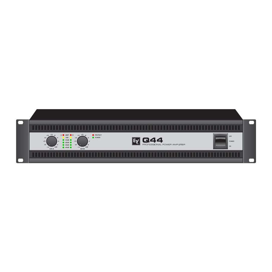
2 Installation 2.1 Controls, Indicators and Connections Front View Input Level Control (CH A, CH B) for channels A and B Level Indicators for channels A and B Protections Indicator (PROTECT) Power On/Off Indicator (POWER) Mains Switch Rear View Mains Input Ground Lift Switch (CIRCUIT ⊥... -
Page 8: Operating Voltage
2.5 Ventilation As with all Electro-Voice power amps with fan cooling, the airflow direction is front-to-rear, obviously because there is more cold air outside of the rack case than inside. The power amplifier remains cooler and dissipating the developing waste heat in a specific direction gets easier. -
Page 9: Groundlift
2.6 Groundlift The ground lift switch allows for eliminating noise loops. When operating the power amplifier together with other equipment in a rack case, setting the switch to the GROUNDED position is recommended. Set the switch to UNGROUNDED, when the power amplifier is operated together with appliances with differing ground potentials. -
Page 10: Audio Input Cabeling
PROFESSIONAL POWER AMPLIFIER Speakon CHANNEL B Table 2.1: Speaker connection using Speakon A and B connectors BRIDGED In BRIDGED mode both amp channels work in push-pull operation to provide doubled output voltage. The audio signal has to be applied to the input connectors of channel A, amplification is set via input level control of channel A only. - Page 11 mandatory. Otherwise, a 6 dB drop in level could result. Please also see illustration 2.11. Due to their immunity against external interference sources, such as dimmers, mains connections, HF-control lines, etc., using balanced cabling and connections is always preferable. Illustration 2.2: Unbalanced connection of input Next to its input connector, each channel provides an individual XLR-type connector (OUTPUT A or OUTPUT B), which is connected in parallel to allow for comfortably daisy-chaining the audio signal for the connection of additional audio equipment.
-
Page 12: Operation
PROFESSIONAL POWER AMPLIFIER 3 Operation 3.1 Volume Control In DUAL and PARALLEL mode, the level controls CH A and CH B on the power amp’s front panel are used to control the amplification of the corresponding channel. Turning the control to the right increases and turning it to the left decreases the volume. - Page 13 PROFESSIONAL POWER AMPLIFIER Owner‘s Manual...
- Page 14 PROFESSIONAL POWER AMPLIFIER Beschreibung ..............16 Willkommen .
-
Page 15: Wichtige Sicherheitshinweise
Lesen Sie diese Hinweise. Heben Sie diese Hinweise auf. Beachten Sie alle Warnungen. Richten Sie sich nach den Anweisungen. Betreiben Sie das Gerät nicht in unmittelbarer Nähe von Wasser. Verwenden Sie zum Reinigen des Gerätes ausschließlich ein trockenes Tuch. Verdecken Sie keine Lüftungsschlitze. Beachten Sie bei der Installation des Gerätes stets die entsprechenden Hinweise des Herstellers. Vermeiden Sie die Installation des Gerätes in der Nähe von Heizkörpern, Wärmespeichern, Öfen oder anderer Wärmequellen. -
Page 16: Beschreibung
PROFESSIONAL POWER AMPLIFIER 1 Beschreibung 1.1 Willkommen Vielen Dank, dass Sie sich für eine Endstufe der Electro-Voice Q Serie entschieden haben. Bitte lesen Sie diese Bedienungsanleitung aufmerksam durch, damit Sie Ihren neuen Electro-Voice Verstärker optimal nutzen können. 1.2 Auspacken und Inspektion Öffnen Sie die Verpackung und entnehmen Sie die Endstufe. -
Page 17: Installation
2 Installation 2.1 Bedienelemente, Anzeigen und Anschlüsse Frontseite Eingangspegel-Regler (CH A, CH B) für Kanal A bzw. B Pegelanzeige für Kanal A bzw. B Anzeige Schutzschaltung (PROTECT) Anzeige Betrieb (POWER) Netzschalter Rückseite Netzeingang Schalter Groundlift (CIRCUIT ⊥ TO CHASSIS SWITCH) Typenschild Audioeingangsbuchsen (INPUT A, INPUT B) Audioausgangsbuchsen (OUTPUT A, OUTPUT B) -
Page 18: Betriebsspannung
Abbildung gezeigt. Geeignete Rackwinkel sind als Zubehör erhältlich. 2.5 Kühlung Bei allen lüftergekühlen Endstufen von Electro-Voice strömt die Luft von der Frontseite zur Rückseite, da kühle Frischluft eher außerhalb des Racks zur Verfügung steht als innerhalb. Die Endstufe bleibt kühler und die entstehende Abwärme kann gezielter abgeführt werden. -
Page 19: Groundlift
ACHTUNG: Die Lüftungsöffnungen der Endstufe dürfen nicht blockiert/verschlossen werden. Bei fehlen- der Kühlung kann sich die Endstufe automatisch abschalten. Halten Sie alle Lüftungsöffnun- gen frei von Staubablagerungen, die den Luftstrom behindern würden. Betreiben Sie die Endstufe nicht in der Nähe von Wärmequellen wie Heizlüftern, Öfen oder an- deren Geräten, die Hitze abstrahlen. - Page 20 PROFESSIONAL POWER AMPLIFIER Typische Lautsprecherverkabelung Die erste Möglichkeit für den Anschluss von Lautsprechern in den Betriebsarten DUAL und PARALLEL ist die Verwendung beider Speakon- Buchsen, wobei in jeder der Buchsen der Lautsprecher jeweils an den Anschlüssen 1+ und 1- angeschlossen wird, siehe nebenstehende Abbildung.
-
Page 21: Verkabelung Des Audio-Eingangs
ACHTUNG: Im Brückenbetrieb darf die angeschlossene Last 4 Ω nicht unterschreiten. Es können sehr hohe Spannungen am Ausgang produziert werden. Die angeschlossenen Lautsprecher müs- sen für derart hohe Spannungen ausgelegt sein. Beachten Sie unbedingt die Leistungsanga- ben im Datenblatt des jeweiligen Lautsprechers und vergleichen Sie diese mit der entsprechenden Ausgangsleistung der Endstufe. -
Page 22: Betrieb
PROFESSIONAL POWER AMPLIFIER 3 Betrieb 3.1 Eingangspegel-Regler In den Betriebsarten DUAL und PARALLEL regeln die Eingangspegel-Regler CH A und CH B an der Frontseite der Endstufe die Verstärkung des jeweiligen Kanals. Drehung nach rechts erhöht die Lautstärke, Drehung nach links verringert die Lautstärke. Im Brückenbetrieb (BRIDGED) regelt nur der Drehknopf von Kanal A (CH A) die Lautstärke, die Drehknopf-Einstellung von Kanal B (CH B) wird ignoriert. -
Page 23: Specifications/Technische Daten
14.8 kg (32.6 lbs) 2-Way crossover, internal filter card, 24 dB, LR 330 Hz (NRS 90249), 500 Hz (NRS 90250), 800 Hz (NRS 90251), 1200 Hz (NRS 90252) Owner‘s Manual / Bedienungsanleitung Q1212 8 Ω 2 Ω 4 Ω 8 Ω... - Page 24 PROFESSIONAL POWER AMPLIFIER Block Diagram / Blockschaltbild Owner‘s Manual / Bedienungsanleitung...
- Page 25 PROFESSIONAL POWER AMPLIFIER Dimensions / Abmessungen Owner‘s Manual / Bedienungsanleitung...
- Page 26 PROFESSIONAL POWER AMPLIFIER Owner‘s Manual / Bedienungsanleitung...
- Page 27 PROFESSIONAL POWER AMPLIFIER Owner‘s Manual / Bedienungsanleitung...
- Page 28 Americas Bosch Communications Systems 12000 Portland Ave South Burnsville, MN 55337, USA USA: Phone:1-800-392-3497 Fax: 1-800-955-6831 Canada: Phone: 1-866-505-5551 Fax:1-866-336-8467 Latin America: Phone: 1-952-887-5532 Fax: 1-952-736-4212 Europe, Africa & Middle-East Germany: Bosch Communications Systems EVI Audio GmbH Hirschberger Ring 45 D-94315 Straubing, Germany Phone: +49 9421 706-0 Fax: +49 9421 706-265...