Table of Contents
Advertisement
Service
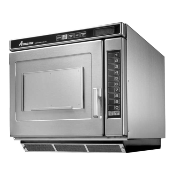
Commercial Microwave Oven
2001 Models
Service Manual for Amana
This manual is to be used by qualified appliance
technicians only. Amana does not assume any
responsibility for property damage or personal
injury for improper service procedures done by
an unqualified person.
®
This Base Manual covers all
Commerical Microwave Ovens.
Refer to individual Technical Sheet
for information on specific models.
ASE7000
ASE9000
MC23MP
MC23MPT
MC23MPT2
RC17S
RC17SD2
RC17SED
RC22S
RC22S3
RC25S
RC27S
RC30S
RS2240003
Revision 0
October 2001
Advertisement
Table of Contents

Related Manuals for Amana ASE7000


Summary of Contents for Amana ASE7000
- Page 1 RC27S ® Service Manual for Amana RC30S This manual is to be used by qualified appliance technicians only. Amana does not assume any responsibility for property damage or personal injury for improper service procedures done by an unqualified person. RS2240003...
-
Page 2: Important Information
(such as exposure to electrical shock) may result. CAUTION Amana will not be responsible for any injury or property damage from improper service procedures. If prefroming service on your own product, assume responsibility for any personal injury or property damage which may result. -
Page 3: Table Of Contents
Record Keeping and Notification After Measurement ......23 Troubleshooting Power up .............. 24 Standby Condition ..........25 Cook Condition ............. 26 Amana • 2800 220thTrail • PO Box 8901 • Amana, Iowa • 52204 • Printed in the U.S.A. RS2240003 Rev. 0... -
Page 4: Important Product Information
Important Product Information WARNING WARNING Precautions to be observed before and during To avoid risk of electrical shock, personal injury or servicing to avoid possible exposure to excessive death; make sure to follow grounding instructions. microwave energy or electrical shock, disconnect power to oven. -
Page 5: Important Safety Information
Amana Service Department immediately for further 3. Oven should never be operated if door does not fit direction. Amana will contact the proper Government properly against seal, hinge/hinge bearings are Agency upon verification of test results. damaged or broken; choke is damaged, (pieces 12. - Page 6 Important Safety Information CAUTION To avoid risk of personal injury or death of fire in the oven cavity: • DO NOT overcook food. Carefully attend equipment if paper, plastic or other combustible materials are placed inside the equipment to facilitate cooking. •...
-
Page 7: Product Information
Product Information Antenna Transformer High Voltage Distributes microwave energy throughout the cavity. High voltage transformer is used in this unit, which supplies high voltage A.C. for operation of the magnetron tube. Blower/Fan Assembly Circulates cooling air throughout the microwave oven High Voltage Capacitor compartment and cavity. -
Page 8: Specifications
Specifications ASE7000, ASE9000, RC17S, RC17SD2, RC22S, RC22S3, RC25S, RC27S, RC30S Nominal Microwave Energy (IEC705) 1700 W 2200 W 2500 W 2700 W 3000 W Power Source Voltage AC 208/230 208/230 208/230 208/230 208/230 Frequency 60 Hz 60 Hz 60 Hz... - Page 9 Specifications MC23MP, MC23MPT, MC23MPT2 Nominal Microwave Energy (IEC705) 2200 W Power Source Voltage AC 208/230 Frequency 60 Hz Amperage 20 A Single Phase, 3-wire ground Power Frequency 2450 MHz Power Consumption 3200 W Receptacle and Plug 20 Amp Hubbell 320P6WM2 RS2240003 Rev.
-
Page 10: Installation
Installation Grounding Instructions Radio Interference NOTE: Do not under any circumstances cut or remove Microwave operation may cause interference to radio, grounding prong from the plug or bend power prongs to fit television or a similar oven. Reduce or eliminate receptacle other than one shown for your equipment. -
Page 11: Care And Cleaning
Care and Cleaning Cleaning Oven Cavity Clean oven frequently to maximize oven life, performance, and efficiency. A dirty oven cooks inefficiently because Rub vigorously with nylon scouring pad to loosen debris. moisture, spills, and grease absorb microwave energy. Wipe clean with warm, damp clean cloth. •... -
Page 12: Component Testing Procedures
Component Testing Procedures WARNING To avoid risk of electrical shock, personal injury or death; disconnect power to oven and discharge capacitor before servicing, unless testing requires power. Illustration Component Test Results Thermal cutout Disconnect all wires from TCO. Measure resistance across terminals. Magnetron TCO ........ - Page 13 Component Testing Procedures WARNING To avoid risk of electrical shock, personal injury or death; disconnect power to oven and discharge capacitor before servicing, unless testing requires power. Illustration Component Test Results Auto Transformer Discharge Capacitors Remove all wires from terminals. 208 V Measure resistance from: 230 V to 0 V ..........
- Page 14 Component Testing Procedures WARNING To avoid risk of electrical shock, personal injury or death; disconnect power to oven and discharge capacitor before servicing, unless testing requires power. Illustration Component Test Results Side touch panel Trace Measurement Continuity is indicated as 100 3 &...
- Page 15 Component Testing Procedures WARNING To avoid risk of electrical shock, personal injury or death; disconnect power to oven and discharge capacitor before servicing, unless testing requires power. H.V. board Pin 1 Pin 1 Pin 28 Pin 1 Pin 50 Pin 1 Pin 1 Pin 1 Pin 1...
- Page 16 Component Testing Procedures WARNING To avoid risk of electrical shock, personal injury or death; disconnect power to oven and discharge capacitor before servicing, unless testing requires power. H.V. Board Relay Test Three Magnetron Models Relay Function Test Set-Up Meter Probe Placement Results Setting All wires...
- Page 17 Component Testing Procedures WARNING To avoid risk of electrical shock, personal injury or death; disconnect power to oven and discharge capacitor before servicing, unless testing requires power. Three Magnetron Models H.V. System # 1 H.V. System # 2 H.V. System # 3 Top Rear Magnetron Top Front Magnetron Bottom Magnetron...
- Page 18 Component Testing Procedures WARNING To avoid risk of electrical shock, personal injury or death; disconnect power to oven and discharge capacitor before servicing, unless testing requires power. Two Magnetron Models H.V. System # 1 H.V. System # 3 Top Rear Magnetron Bottom Magnetron Left Transformer Right Transformer...
-
Page 19: Power Testing Procedure
Power Test (Traditional Test Method) Test equipment required is Amana power test kit R0157397 (Fahrenheit), or Menumaster power test kit M95D5 (Celsius). 1. Fill the plastic container to the 1000 ml. line with cool tap water. -
Page 20: Display Diagnostics
Display Diagnostics W ARNING To avoid risk of electrical shock, personal injury, or death, disconnect power to oven and discharge capacitor before servicing, unless testing requires it. CAUTION All repairs as described in this troubleshooting section are to be performed only after the caution procedures one through eight listed below have been followed. -
Page 21: Service Test
Service Test WARNING To avoid risk of electrical shock, personal injury or death; disconnect power to oven and discharge capacitor before servicing, unless testing requires power. I T E M S T G Q T Y P O W E R NOTE: Unit must be in OFF condition COOK L M T... -
Page 22: Rs2240003 Rev
Service Test WARNING To avoid risk of electrical shock, personal injury or death; disconnect power to oven and discharge capacitor before servicing, unless testing requires power. Press Display Component Evaluation I T E M S T G Q T Y P O W E R This mode is NOT active with these models. -
Page 23: Microwave Leakage Test
WARNING DANGER Check for radiation leakage after servicing. Should the leakage be more than 4mW/cm inform Amana To avoid risk of personal injury or death avoid immediately. After repairing or replacing any radiation contacting any high voltage components. safety device, keep a written record for future reference, as required by D.H.H.S. -
Page 24: Troubleshooting
Troubleshooting Power Up Plug oven into power source with oven door closed. Proceed to DISPLAY DIAGNOSTICS. Error Code Appears. ITEM POWER COOK PREHEAT READY STANDBY LEVEL 1. No line voltage. 2. Inoperative power cord. 3. Inoperative fuse. 4. Inoperative display board. 5. -
Page 25: Standby Condition
Troubleshooting Standby Condition Open oven door. ITEM POWER Inoperative interlock switch assembly (primary). Inoperative H.V. board. Broken or improper wire connections. COOK PREHEAT READY STANDBY LEVEL Inoperative light bulb. Inoperative light socket. Oven light is on? Inoperative auto-transformer. Inoperative H.V. board. Broken or improper wire connections. -
Page 26: Cook Condition
Troubleshooting Cook Condition Place cup of water in oven and close oven door. Beep not programmed into oven. Flashing Pad not programmed. Display indicates 00:00 and beeps rapidly. ITEM POWER Inoperative touch panel. Inoperative H.V. board. COOK Broken or improper wire connections. PREHEAT READY STANDBY... -
Page 27: Disassembly
Disassembly WARNING To avoid the risk of electrical shock, personal injury or death; disconnect power to oven and discharge capacitors before following any disassembly procedure. Door Handle Inner Door Ring Assembly Remove door handle by removing plactic plugs to gain 1. -
Page 28: Outer Case
Disassembly WARNING To avoid the risk of electrical shock, personal injury or death; disconnect power to oven and discharge capacitors before following any disassembly procedure. Outer Case Top Touch Panel Assembly 1. Remove screws securing outer case to chassis, see 1. -
Page 29: Interlock Switch Module
Disassembly WARNING To avoid the risk of electrical shock, personal injury or death; disconnect power to oven and discharge capacitors before following any disassembly procedure. Top Rear Magnetron Interlock Switch Module 1. See “Component Location” Figure 2, for location. 1. See “Component Location” Figure 1, for location. 2. -
Page 30: Triacs
Disassembly WARNING To avoid the risk of electrical shock, personal injury or death; disconnect power to oven and discharge capacitors before following any disassembly procedure. Microwave Blower Wheel and Motor Magnetron Cutout (TCO) 1. Remove outer case and back panel. 1. -
Page 31: Replacing Oven Light Bulb
6. Apply a generous bead of RTV sealent around perimeter of tray. 7. Apply a light water spray to the fresh RTV sealent. 8. Using RTV scrapper, Amana part # R0000039, remove excess RTV. NOTE: Allow RTV to set for 1 hour before using. -
Page 32: Fuse
Disassembly WARNING To avoid the risk of electrical shock, personal injury or death; disconnect power to oven and discharge capacitors before following any disassembly procedure. Fuse Replacing Oven Light Bulb 1. See “Component Location” Figure 3, for location. 2. Remove outer case. WARNING 3. -
Page 33: Component Location
Disassembly WARNING To avoid the risk of electrical shock, personal injury or death; disconnect power to oven and discharge capacitors before following any disassembly procedure. Component Location Display Module Touch Panel (Top) Antennas Top front antenna on 3 tube ovens are blue tipped. All other antennas are plain tipped. - Page 34 Disassembly WARNING To avoid the risk of electrical shock, personal injury or death; disconnect power to oven and discharge capacitors before following any disassembly procedure. Splatter Shield Oven Tray Magnetron TCO's Magnetrons Filter Rear Flow Divider Exhaust Duct Flow Divider Bottom Exhaust Duct Bottom...
- Page 35 Disassembly WARNING To avoid the risk of electrical shock, personal injury or death; disconnect power to oven and discharge capacitors before following any disassembly procedure. Fan Blade Oven Light Socket Fan Motor Auto Transformer High Voltage Board Triac Terminal Block Fuse Block and Fuse Back Panel...
- Page 36 Disassembly WARNING To avoid the risk of electrical shock, personal injury or death; disconnect power to oven and discharge capacitors before following any disassembly procedure. This page intentionally left blank. RS2240003 Rev. 0...
- Page 37 Appendix A A–1 RS2240003 Rev. 0...
-
Page 38: Operating Instructions For Ase7000, Ase9000, Rc17S, Rc17Sd2, Rc22S, Rc22S3, Rc25S, Rc27S, Rc30S
Operating Instructions for ASE7000, ASE9000, RC17S, RC17SD2, RC17SED, RC22S, RC22S3, RC25S, RC27S, RC30S Display and Features Cooking Display DISPLAYS DESCRIPTION Displays cooking time. If stage cooking is 00:00 programmed, total cooking time is displayed. COOK LEVEL displays the current microwave COOK LEVEL power level. -
Page 39: Manual Time Entry
Operating Instructions for ASE7000, ASE9000, RC17S, RC17SD2, RC17SED, RC22S, RC22S3, RC25S, RC27S, RC30S Display and Features Single Pad Programming Start Pad The start pad is This feature enables each numbered pad to be used to begin a programmed for a specific use, such as cooking a... -
Page 40: Microwave Cooking
Operating Instructions for ASE7000, ASE9000, RC17S, RC17SD2, RC17SED, RC22S, RC22S3, RC25S, RC27S, RC30S Manual Time Entry Microwave Cooking To cook food using a specific entered time and power level. Microwave cooking uses high 1. Open oven door and place food in oven. Close door. -
Page 41: Programming Pads
Operating Instructions for ASE7000, ASE9000, RC17S, RC17SD2, RC17SED, RC22S, RC22S3, RC25S, RC27S, RC30S What is stage Programming Pads cooking? Oven is shipped from the factory set for single pad programming. To Stage cooking enables change the oven default to double pad programming, see User Option several different cooking cycles, or section. -
Page 42: User Options
Operating Instructions for ASE7000, ASE9000, RC17S, RC17SD2, RC17SED, RC22S, RC22S3, RC25S, RC27S, RC30S User Options H ID D E N P A D Changing user options Didn’t like an option? Options such as single or double pad programming and beep volume can be changed to suit individual preferences. -
Page 43: Operating Instructions For Dq22Hsi
Operating Instructions for DQ22HSI Display and Features Cooking Display DISPLAYS DESCRIPTION Displays cooking time. If stage cooking is 00:00 programmed, total cooking time is displayed. COOK LEVEL displays the current microwave COOK LEVEL power level. 100 is the highest setting (full power), There are words in the and 0 is lowest (no microwave energy used). - Page 44 Operating Instructions for DQ22HSI Display and Features Double Pad Programming START Pad The start pad is This feature enables 100 programmed entries to be used to begin a made. Using double pad programming with the menu manual time entry option increases the number of entries possible to a cooking cycle.
- Page 45 7. At end of cooking cycle oven beeps and shuts off. don displays. Preprogrammed Pads To cook food using pads preprogrammed with cooking sequences. All pads come preprogrammed from the Amana factory. ® NOTE: Your Dairy Queen boosting oven is pre-programmed at the factory for double pad programming.
-
Page 46: Programming Pads
Operating Instructions for DQ22HSI Programming Pads Oven is shipped from the factory set for double pad programming. To What is stage program the amount of time or power level setting for a pad: cooking? 1. Press MENU button until desired menu number displays. Stage cooking enables 2. - Page 47 Operating Instructions for DQ22HSI User Options H ID D E N P A D Changing user options Options such as single or double pad programming, beep volume, and Didn’t like an option? maximum cooking time can be changed to suit individual preferences. Factory settings are marked in bold.
-
Page 48: Operating Instructions For Mc23Mp, Mc23Mpt, Mc23Mpt2
Equipment Set-Up and Close Procedures Introduction WARNING This Amana oven uses microwave technology to restore heat that is lost during the assembly of menu items. This unit may also be used in To avoid risk of electrical shock, preparation of specific ingredients or components of a menu item. -
Page 49: The Control Panel
Operating Instructions for MC23MP, MC23MPT, MC23MPT2 The Control Panel Numbers (1-0) Cooking Display Select desired menu DISPLAYS DESCRIPTION item and quantity program for preset programs. Displays cooking time. If stage cooking is 00:00 Numbers are also used to enter programmed, total cooking time is displayed. cooking times during programming mode. - Page 50 Operating Instructions for MC23MP, MC23MPT, MC23MPT2 Summary of Manual Manual Time Entry Override 1. Open oven door and place food in To cook food using a specific entered time and power level. oven. 1. Open oven door and place food in oven. Close door. 2.
- Page 51 Operating Instructions for MC23MP, MC23MPT, MC23MPT2 Summary of Changing Programming Items Preset Menu Items To program the amount of time or power level setting for a pad: 1. ITEM must flash in display. 2. Press PROGRAM SAVE pad. 1. ITEM must flash in display. 3.
- Page 52 Operating Instructions for MC23MP, MC23MPT, MC23MPT2 User Options Changing user options Options such as single or double pad programming and beep volume can be Change an option too soon? changed. Factory settings are marked in bold. To change the oven back to the factory To change options READY must display without ITEM: 1.