Table of Contents
Advertisement
Quick Links
120 0W /R-2 2JT
BEFORE SERVICING ...................................................................................................... INSIDE FRONT COVER
MICROWAVE MEASUREMENT PROCEDURE ................................................................................................... 2
FOREWORD .......................................................................................................................................................... 3
PRODUCT SPECIFICATIONS .............................................................................................................................. 4
GENERAL INFORMATION ................................................................................................................................... 4
OPERATION .......................................................................................................................................................... 6
TROUBLE SHOOTING GUIDE/ TEST PROCEDURE ........................................................................................ 10
TOUCH CONTROL PANEL ................................................................................................................................. 20
COMPONENT REPLACEMENT AND ADJUSTMENT PROCEDURE ................................................................ 30
PICTORIAL DIAGRAM ........................................................................................................................................ 37
CONTROL PANEL CIRCUIT ............................................................................................................................... 38
PRINTED WIRING BOARD ................................................................................................................................. 39
PARTS LIST ........................................................................................................................................................ 40
PACKING AND ACCESSORIES ......................................................................................................................... 43
SHARP CORPORATION
SERVICE MANUAL
MODEL
DOUB LE
EXPR ESS
QUAN TITY
In the interest of user-safety the oven should be restored to its original
DEFR OST
1
11
12
2
condition and only parts identical to those specified should be used.
13
3
4
14
WARNING TO SERVICE PERSONNEL: Microwave ovens con-
5
15
6
16
tain circuitry capable of producing very high voltage and
7
17
18
8
9
current, contact with following parts may result in a severe,
19
0
20
SELE CTAT IME
STOP /CLEA R
possibly fatal, electrical shock. (High Voltage Capacitor, High
SELEC TAPOW ER
STAR T
SET
CHEC K
SIGN AL
Voltage Power Transformer, Magnetron, High Voltage Recti-
fier Assembly, High Voltage Harness etc..)
TABLE OF CONTENTS
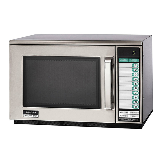
COMMERCIAL
MICROWAVE OVEN
R-22JT
This document has been published to be used for after
sales service only.
The contents are subject to change without notice.
R-22JT
S0407R22JT///
Page
Advertisement
Table of Contents
Troubleshooting

Related Manuals for Sharp R-22JT


Summary of Contents for Sharp R-22JT
-
Page 1: Table Of Contents
R-22JT SERVICE MANUAL S0407R22JT/// COMMERCIAL MICROWAVE OVEN R-22JT MODEL DOUB LE EXPR ESS QUAN TITY In the interest of user-safety the oven should be restored to its original DEFR OST condition and only parts identical to those specified should be used. -
Page 2: Precautions To Be Observed Before And During Service To Avoid Possible Exposure To Excessive Microwave Energy
Before servicing an operative unit, perform a microwave emission check as per the Microwave Measurement Procedure outlined in this service manual. If microwave emissions level is in excess of the specified limit, contact SHARP ELECTRONICS CORPORATION immediately @1-800-237-4277. If the unit operates with the door open, service person should 1) tell the user not to operate the oven and 2) contact SHARP ELECTRONICS CORPORATION and the Food and Drug Administration's Center for Devices and Radiological Health immediately. -
Page 3: Warning To Service Personnel
R-22JT WARNING TO SERVICE PERSONNEL Microwave ovens contain circuitry capable of pro- ducing very high voltage and current, contact with following parts may result in a severe, possibly fatal, electrical shock. (Example) High Voltage Capacitor, High Voltage Power Trans- former, Magnetron, High Voltage Rectifier Assem- bly, High Voltage Harness etc.. -
Page 4: Microwave Measurement Procedure
R-22JT MICROWAVE MEASUREMENT PROCEDURE A. Requirements: 1) Microwave leakage limit (Power density limit): The power density of microwave radiation emitted by a microwave oven should not exceed 1mW/cm at any point 5cm or more from the external surface of the oven, measured prior to acquisition... -
Page 5: Foreword
MICROWAVE OVEN GENERAL INFORMATION R-22JT FOREWORD This Manual has been prepared to provide Sharp Electronics Corp. OPERATION Service Personnel with Operation and Service Information for the SHARP MICROWAVE OVEN, R-22JT. It is recommended that service personnel carefully study the entire... -
Page 6: General Information
R-22JT SPECIFICATION ITEM DESCRIPTION Power Requirements 120 Volts 1.95 kW Approx. 17 A 60 Hertz / Single phase, 3 wire grounded Power Output 1200 watts (IEC Test Procedure) Operating frequency of 2450MHz Case Dimensions Width 20-1/8" (510mm) Height 13-1/4" (335mm) Depth 18-1/2" (470mm) Cooking Cavity Dimensions Width 13"... - Page 7 R-22JT OVEN DIAGRAM 1. Touch control panel 2. Door latch openings 3. Ceramic shelf 4. Splash cover 5. Oven light NO. X2 CHECK 6. Air intake filter 7. Air intake openings 8. Door seals and sealing surfaces DOUBLE EXPRESS 9. Door hinges...
-
Page 8: Operation
R-22JT OPERATION DESCRIPTION OF OPERATING SEQUENCE The following is a description of component functions during (1), (2) are activated with the following results. The oven operation. circuits to the high voltage components are de-energized, and the digital read-out displays " . " and cooking is OFF CONDITION cancelled (in the case of Memory cooking). - Page 9 R-22JT TWO MAGNETRON OPERATION SYSTEM OPERATION OF MAGNETRON Two magnetrons (1), (2) are equipped in order to get higher COMMERCIAL microwave power output. The primary windings of the FREQUENCY (60HZ) power transformers (1), (2) are connected so that each magnetron can be oscillated alternatively according to the...
- Page 10 R-22JT SCHEMATIC NOTE: CONDITION OF OVEN 1. FOR 1MINUTE AFTER DOOR OPENED. 2. " . " APPEARS ON DISPLAY. PRIMARY SECONDARY INTERLOCK INTERLOCK RELAY (1) SWITCHES POWER TRANSFORMER(1) PRIMARY CAPACITOR (1) INTERLOCK RELAY (2) NOISE FILTER AC 2100V RY-3 RY-2...
-
Page 11: Description And Function Of Components
R-22JT DESCRIPTION AND FUNCTION OF COMPONENTS DOOR OPEN MECHANISM opened. Monitor switch (2) is intended to render the oven inoperative by means of blowing the monitor fuse, when the 1. The door release lever is pulled. contacts of the primary interlock relay (2) and secondary 2. -
Page 12: Troubleshooting Guide
R-22JT magnetrons. This air is channelled through the oven cavity OVEN THERMISTOR to remove steam and vapours given off from the heating The thermistor is a negative temperature coefficient type. foods. It is then exhausted through the exhausting air vents The temperature in the exhaust duct is detected through the at the oven cavity. -
Page 13: Trouble Shooting Guide/ Test Procedure
R-22JT CK = Check / RST = Reset / RE = Replace A B C D E F F G H I CK CK K L M N N N O CK CK CK CK CK TEST PROCEDURE RST RST... - Page 14 R-22JT TEST PROCEDURES PROCEDURE COMPONENT TEST LETTER MAGNETRON ASSEMBLY TEST 1. Disconnect the power supply cord, and then remove outer case. 2. Open the door and block it open. 3. Discharge two high voltage capacitors. 4. To test for an open filament, isolate the magnetron from the high voltage circuit. A continuity check across the magnetron filament leads should indicate less than 1 ohm.
- Page 15 R-22JT TEST PROCEDURES PROCEDURE COMPONENT TEST LETTER 8. Run the oven and check all functions. (HIGH VOLTAGES ARE PRESENT AT THE HIGH VOLTAGE TERMINAL, SO DO NOT ATTEMPT TO MEASURE THE FILAMENT AND HIGH VOLTAGE.) HIGH VOLTAGE RECTIFIER (1) AND/ OR (2) TEST 1.
- Page 16 R-22JT TEST PROCEDURES PROCEDURE COMPONENT TEST LETTER of the switch. The meter should indicate an open circuit with the door open and a closed circuit with the door closed. If improper operation is indicated, replace the door sensing switch. 5. Reconnect all leads removed from components during testing.
- Page 17 R-22JT TEST PROCEDURES PROCEDURE COMPONENT TEST LETTER be replaced with "monitor fuse and monitor switch assembly" part number FFS-BA033WRKZ, even if the monitor switch operates normally. The monitor fuse and monitor switch assembly is comprised of a 20 ampere fuse and switch.
- Page 18 R-22JT TEST PROCEDURES PROCEDURE COMPONENT TEST LETTER NOISE FILTER TEST 1. Disconnect the power supply cord, and then remove outer case. 2. Open the door and block it open. 3. Discharge high voltage capacitor. 4. Disconnect the lead wires from the terminal the noise filter. Using an ohmmeter, check between the terminals as described in the following table.
- Page 19 R-22JT TEST PROCEDURES PROCEDURE COMPONENT TEST LETTER 8) Run the oven and check all functions. 2. Control Unit The following symptoms indicate a defective control unit. Before replacing the control unit, perform the Key unit test (Procedure M) to determine if control unit is faulty.
- Page 20 R-22JT TEST PROCEDURES PROCEDURE COMPONENT TEST LETTER RELAY TEST 1. Disconnect the power supply cord, and then remove outer case. 2. Open the door and block it open. 3. Discharge two high voltage capacitors. 4. Disconnect the leads to the primary of the power transformer.
- Page 21 R-22JT TEST PROCEDURES PROCEDURE COMPONENT TEST LETTER 6) Reconnect all leads removed from components during testing. 7) Re-install the outer case (cabinet). 8) Reconnect the power supply cord after the outer case is installed. 9) Run the oven and check all functions.
-
Page 22: Touch Control Panel Assembly
R-22JT TOUCH CONTROL PANEL ASSEMBLY OUTLINE OF TOUCH CONTROL PANEL The touch control section consists of the following units as 15) High Voltage Monitoring Circuit. shown in the touch control panel circuit. This circuit detects problems in the magnetron / high voltage... - Page 23 R-22JT DESCRIPTION OF LSI LSI(IZA633DR) The I/O signal of the LSI(IZA633DR) is detailed in the following table. Pin No. Signal Description Power source voltage: +5V. VC voltage of power source circuit input. VEE/AVSS Connected to GND VREF Connected to VC. (+5V) Temperature measurement input: INTAKE THERMISTOR.
- Page 24 R-22JT Pin No. Signal Description Digit selection signal. The relation between digit signal and digit are as ß(60Hz) follows: Digit signal Digit P42 ..... 1st. P43 ....2nd. P44 ..... 3rd. P45 ..... 4th. Normally, one pulse is output in every ß period, and input to the grid of the light-emitting diode.
- Page 25 R-22JT Pin No. Signal Description 57-59 P37-P35 Terminal not used. Key strobe signal. Signal applied to touch-key section. A pulse signal is input to P27, P26, P25 and P24 terminals while one of G4 line keys on key matrix is touched.
-
Page 26: Touch Control Panel
R-22JT SERVICING 1. Precautions for Handling Electronic Components 4) Re-install the outer case (cabinet). This unit uses CMOS LSI in the integral part of the 5) Re-connect the power supply cord after the outer circuits. When handling these parts, the following case is installed. - Page 27 R-22JT 3) Practice for inputting total using times (Ex. 310000 times). PROCEDURE FOR CHECKING/CLEARING SERVICE COUNTS OF MICROWAVE OVEN ... Flashing / ... 0.1sec BUZZER DISPLAY INDICATOR TONE The following procedure enables the servicer to obtain the (Door close) total using times (cook cycles) since the microwave oven is...
- Page 28 R-22JT 5) Practice for cancelling total using times and total operation DISPLAY PAUSE time (user and service) and all other counter. End of each stage After 10% of total cooking time is passed ... Flashing / ... 0.1sec BUZZER DISPLAY...
- Page 29 R-22JT MEMORY READJUSTMENT PROCEDURE 1. To set the standard voltage When the IC2 is changed in the control unit, the standard voltage must be set again for power supply check. The power supply must be set 120V, and 120V connector in control unit installed.
-
Page 30: Check Procedure For Error Code Ee1, Ee2
R-22JT A CHECK PROCEDURE FOR ERROR CODE INDICATION EE1, EE2 When the error code EE1 or EE2 is displayed, carry out following procedures and find out the defective parts. When oscillation is unstable due to defect of upper and/or lower magnetron or defective driving circuits, error code indications EE1 or EE2 do not function properly. - Page 31 R-22JT 3]. [JUDGMENT PROCEDURE FOR LOWER MAGNETRON AND ITS CIRCUIT] Disconnect the power supply cord. Disconnect lead wires to the interlock relay RY2 to avoid operation of lower magnetron circuit. Lead wires to the interlock relay RY3 should be connected.
-
Page 32: Component Replacement And Adjustment Procedure
WARNING FOR WIRING To prevent an electric shock, take the following pre- and Oven cavity. cautions. 3) Sharp edge: 1. Before wiring, Bottom plate, Oven cavity, Waveguide flange, 1) Disconnect the power supply cord. Chassis support and other metallic plate. - Page 33 R-22JT 8. Disconnect the power supply cord from the supply 11.Loosen the tab of the cord bushing, and remove the harness. power supply cord with the cord bushing from the rear 9. Remove the one (1) screw holding the grounding wire of cabinet.
- Page 34 3. Where the portions have been snipped off bend the 3. Discharge two high voltage capacitors. portions flat. No sharp edge must be evident after 4. Disconnect the wire leads from the stirrer motor (upper). removal of the stirrer motor cover.
-
Page 35: Control Panel Assembly And Control Unit Removal
R-22JT 2. Open the oven door and block it open. Terminal 3. Discharge two high voltage capacitors. ® 4. Pushing the lever of positive lock connector, pull down Positive lock® connector the connector from the terminal. 5. Now, the connector is free. -
Page 36: Pictorial Diagram
R-22JT DOOR SENSING SWITCH/SECONDARY INTERLOCK SWITCHES (1), (2) AND MONITOR SWITCHES (1), (2) REPLACEMENT REMOVAL procedure. 1. Disconnect the power supply cord and then remove DOOR SENSING SWITCH outer case, referring to "OUTER CASE, REAR CABINET Mount the door sensing switch in the lower position of AND POWER SUPPLY CORD REMOVAL". -
Page 37: Door Replacement
R-22JT DOOR REPLACEMENT REMOVAL After adjustment, make sure of the following: 1. Disconnect the power supply cord and then remove 1. Door latch heads smoothly catch the latch hook through outer case, referring to "OUTER CASE, REAR CABINET the latch holes, and the latch head goes through the AND POWER SUPPLY CORD REMOVAL". - Page 38 R-22JT DOOR CASE REMOVAL DOOR COMPONENTS REMOVAL 1. Remove the door assembly from oven cavity, referring to DOOR HANDLE REMOVAL "DOOR REMOVAL". 1. Remove the door assembly from oven cavity, referring to 2. Remove choke cover from door panel, referring to "DOOR REMOVAL".
- Page 39 R-22JT...
- Page 40 R-22JT...
-
Page 41: Printed Wiring Board
R-22JT Figure S-3. Printed Wiring Board... -
Page 42: Parts List
R-22JT PARTS LIST ∆ Note: The parts marked “ ” may cause undue microwave exposure. The parts marked “*” are used in voltage more than 250V. REF. NO. PART NO. DESCRIPTION Q'TY CODE ELECTRIC PARTS 1- 1 FPWBFA383WRKZ Noise filter... -
Page 43: Oven Parts
R-22JT REF. NO. PART NO. DESCRIPTION Q'TY CODE VSDTB143ES/-3 Transistor (DTB143ES) RH-TZA036CBE0 Transistor (KRC101M) Q22-23 VSDTD143ES/-3 Transistor (DTD143ES) RH-TZA037CBE0 Transistor (KRA101M) R3-5 VRD-Q12EF472J Resistor 4.7k ohm 1/4W VRD-Q12EF101J Resistor 100 ohm 1/4W VRD-Q12EF153J Resistor 15k ohm 1/4W VRD-Q12EF272J Resistor 2.7k ohm... -
Page 44: Door Parts
R-22JT REF. NO. PART NO. DESCRIPTION Q'TY CODE 4-35 FFIL-A005WRK0 Air intake filter assembly 4-36 HDECEA001WRP0 Decoration sash 4-37 HDECQA146WRM0 Corner cap left 4-38 PCUSGA409WRP0 Cushion 4-39 PCOVPA310WRF0 Splash cover 4-40 LANGQA512WRP0 Thermistor angle 4-41 LANGTA408WRWZ Lamp glass mounting plate... -
Page 45: Packing And Accessories
1. MODEL NUMBER 2. REF. NO. 3. PART NO. 4. DESCRIPTION Order Parts from the authorized SHARP parts Distributor for your area. Defective parts requiring return should be returned as indicated in the Service Policy. PACKING AND ACCESSORIES TOP PAD ASSEMBLY... - Page 46 R-22JT OVEN AND CABINET PARTS 4-20 6-11 7-16 2-5-1 4-23 4-30 4-33 7-16 7-16 4-43 7-16 7-16 7-16 7-16 4-26 7-16 7-16 7-16 4-42 4-27 1-10 7-16 7-16 4-25 4-13 7-16 4-18 1-15 7-12 4-28 4-38 4-29 1-13 7-12 1-14...
- Page 47 R-22JT CONTROL PANEL PARTS 3-2-3 6-15 3-2-2 DOOR PARTS 3-2-1 5-22 5-20 5-14 5-12 5-15 5-18 5-16 5-13 5-17 MISCELLANEOUS 6-16 5-10 5-13 5-21 5-19 5-11 5-10 To power transformer To high voltage capacitor 6-12 Actual wire harness may be different from illustration.
- Page 48 No part of this publication may be reproduced, stored in retrieval systems, or transmitted in any form or by any means, electronic, mechanical, photocopying, recording, or otherwise, without prior written permission of the publisher. '04 SHARP CORP. (11S0.610E) Printed in U.S.A...