Table of Contents
Advertisement
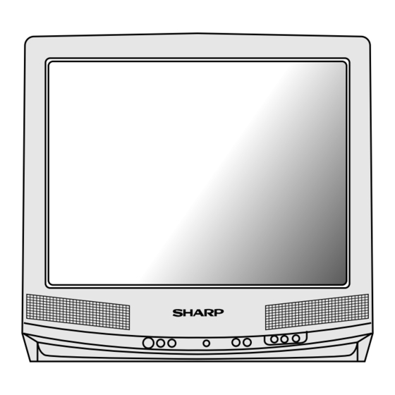
27J-S180
In the interests of user-safety (Required by safety regulations in some countries ) the set should be restored to its
original condition and only parts identical to those specified should be used.
» ELECTRICAL SPECIFICATIONS ............................................................................................. 1
» IMPORTANT SERVICE SAFETY PRECAUTION ..................................................................... 2
» LOCATION OF USER'S CONTROL .......................................................................................... 6
» INSTALLATION AND SERVICE INSTRUCTIONS .................................................................... 9
» CHASSIS LAYOUT ................................................................................................................. 16
» BLOCK DIAGRAM .................................................................................................................. 18
» PRINTED WIRING BOARD ASSEMBLIES ............................................................................. 20
» SCHEMATIC DIAGRAMS ....................................................................................................... 26
» REPLACEMENT PARTS LIST ................................................................................................ 42
» PACKING OF THE SET .......................................................................................................... 60
POWER INPUT ............................................... 120 V AC 60 Hz
POWER RATING ............................................................ 126 W
PICTURE SIZE ...................................... 2,193cm2(340sq inch)
CONVERGENCE ........................................................ Magnetic
SWEEP DEFLECTION ............................................... Magnetic
FOCUS .......................................... Hi-Bi-Potential Electrostatic
INTERMEDIATE FREQUENCIES
Picture IF Carrier Frequency ................................ 45.75 MHz
Sound IF Carrier Frequency ................................. 41.25 MHz
Color Sub-Carrier Frequency ............................... 42.17 MHz
.............................................................................. (Nominal)
AUDIO POWER .........................................................................
OUTPUT RATING ........................... 2.6W (at 10% distortion)
SHARP ELECTRONICS CORPORATION
Service Headquarters: Sharp Plaza, Mahwah, New Jersey 07430-2135
SHARP ELECTRONICS OF CANADA LTD.
335 Britannia Road East Mississauga,Ontario L4Z 1W9 Canada
SERVICE MANUAL
27J-S100/180/260
27J-S100/S260
CJ27S10/26
CJ27S10/26
MODELS
CONTENTS
ELECTRICAL SPECIFICATIONS
SPEAKER
ANTENNA INPUT IMPEDANCE
TUNING RANGES
- 1 -
COLOR TELEVISION
Chassis No. SN-71
SIZE ................................................................... 8cm(Round)
VOICE COIL IMPEDANCE .......................... 8ohm at 400 Hz
VHF/UHF ................................................ 75 ohm Unbalanced
VHF-Channels ........................................................... 2thru 13
UHF-Channels ........................................................ 14thru 69
CATV Channels ....................................................... 1thru 125
............................................................... (EIA, Channel Plan)
Specifications are subject to change without prior
notice.
27J-S100/180/260
CJ27S10/26
S37W727J-S100
Page
Advertisement
Table of Contents

Related Manuals for Sharp 27J-S100

Summary of Contents for Sharp 27J-S100
-
Page 1: Table Of Contents
Specifications are subject to change without prior AUDIO POWER ................. notice. OUTPUT RATING ......2.6W (at 10% distortion) SHARP ELECTRONICS CORPORATION Service Headquarters: Sharp Plaza, Mahwah, New Jersey 07430-2135 SHARP ELECTRONICS OF CANADA LTD. 335 Britannia Road East Mississauga,Ontario L4Z 1W9 Canada - 1 -... -
Page 2: Important Service Safety Precaution
27J-S100/180/260 CJ27S10/26 IMPORTANT SERVICE SAFETY PRECAUTION Service work should be performed only by qualified service technicians who are thoroughly familiar with all safety checks and servicing guidelines which follow: WARNING X-RADIATION AND HIGH VOLTAGE 1. For continued safety, no modification of any circuit LIMITS should be attempted. - Page 3 27J-S100/180/260 CJ27S10/26 IMPORTANT SERVICE SAFETY PRECAUTION (Continued) BEFORE RETURNING THE RECEIVER (Fire & Shock Hazard) Before returning the receiver to the user, perform the following safety checks. 1. Inspect all lead dress to make certain that leads are not pinched or that hardware is not lodged between the chassis and other metal parts in the receiver.
- Page 4 27J-S100/180/260 CJ27S10/26 PRECAUTIONS A PRENDRE LORS DE LA REPARATION Ne peut effectuer la réparation qu' un technicien spécialisé qui s'est parfaitement accoutumé à toute vérification de sécurité et aux conseils suivants. AVERTISSEMENT LIMITES DES RADIATIONS X ET DE LA HAUTE TENSION 1.
- Page 5 27J-S100/180/260 CJ27S10/26 PRECAUTIONS A PRENDRE LORS DE LA REPARATION (Suite) » Toucher avec la sonde d'essai les pièces métalliques VERIFICATIONS CONTRE L'INCEN-DIE ET exposées qui présentent une voie de retour au LE CHOC ELECTRIQUE châssis (antenne, coffret métallique, tête des vis, Avant de rendre le récepteur à...
-
Page 6: Location Of User's Control
27J-S100/180/260 CJ27S10/26 LOCATION OF USER'S CONTROL (27J-S100/CJ27S10) - 6 -... - Page 7 27J-S100/180/260 CJ27S10/26 LOCATION OF USER'S CONTROL 27J-S260/CJ27S26 - 7 -...
- Page 8 27J-S100/180/260 CJ27S10/26 27J-S180 - 8 -...
-
Page 9: Installation And Service Instructions
27J-S100/180/260 CJ27S10/26 INSTALLATION AND SERVICE INSTRUCTIONS Note: (1) When performing any adjustments to resistor controls and transformers use n o n - m e t a l l i c screwdriver or TV alignment tools. Before performing adjustment, TV set must be on at least 15 minutes. - Page 10 S01 to P06(27J-S260/ CJ27S26),S01 to M05 (27J-S100/180/CJ27S10) Select the item you wish to adjust. 3.Data number selection Press the volume up or down button to adjust the data number .
- Page 11 27J-S100/180/260 CJ27S10/26 DATA SERVICE ADJUSTMENT ITEM ADJUSTMENT CONTENTS NUMBER INITIAL VALUE RANGE PICTURE 00-7F TINT 00-7F COLOR 00-7F BRIGHTNESS 00-7F SHARPNESS 00-3F Must be set to "28" VERTICAL PHASE 00-07 Must be set to "00" HORIZONTAL PHASE 00-1F RF-AGC 00-3F...
- Page 12 27J-S100/180/260 CJ27S10/26 Ë Ë Ë Ë Ë adjustment White balance adjustment VCO Adjustment 1. Have unit receive a good local channel. 2. Enter the service mode. select service adjustment "S 1. Connect a digital voltmeter between pin 44 of IC201 03"...
- Page 13 4. Adjust "S18" data value so that text box is positioned level. in the center of the screen. Vertical-size and linearity adjustment Ver-Lin-for 27J-S100/S260,CJ27S10/26 3.58MHz trap adjustment 1. Have unit receive a good local channel. 1. Have unit receive a good local channel.
- Page 14 27J-S100/180/260 CJ27S10/26 P-IN-P ADJUSTMENT MTS ADJUSTMENT (FOR 27J-S260/CJ27S26) MTS level adjustment P-IN-P Y LEVEL adjustment 1. Feed the following monaural signal to pin (14) of 1. Recieve a good local channel. IC3001. 2. Enter the service mode and select service adjust- Monaural signal : 300Hz, 245mVrms ment "P01".
-
Page 15: Description Of Schematic Diagram
27J-S100/180/260 CJ27S10/26 DESCRIPTION OF SCHEMATIC DIAGRAM WAVEFORM MEASUREMENT CONDITIONS: NOTE: 1. Photographs taken on a standard gated color 1. The unit of resistance "ohm" is omitted (K:1000 bar signal, the tint setting adjusted for proper ohms, M:1 Meg ohm). color. The wave shapes at the red, green and 2. -
Page 16: Chassis Layout
27J-S100/180/260 27J-S100/180/260 CJ27S10/26 CJ27S10/26 CHASSIS LAYOUT - 16- - 17-... -
Page 17: Block Diagram
27J-S100/180/260 27J-S100/180/260 CJ27S10/26 CJ27S10/26 BLOCK DIAGRAM CJ27S10 / CJ27S10 - 18 - - 19-... - Page 18 27J-S100/180/260 27J-S100/180/260 CJ27S10/26 CJ27S10/26 PRINTED WIRING BOARD ASSEMBLIES PWB-A Wiring Side - 20- - 21-...
- Page 19 27J-S100/180/260 27J-S100/180/260 CJ27S10/26 CJ27S10/26 PWB-A Chip Parts - 22- - 23-...
- Page 20 27J-S100/180/260 27J-S100/180/260 CJ27S10/26 CJ27S10/26 PWB-H Wiring Side PWB-R Chip Parts PWB-B Wiring Side PWB-R Wiring Side - 24- - 25-...
-
Page 21: Schematic Diagrams
27J-S100/180/260 27J-S100/180/260 CJ27S10/26 CJ27S10/26 SCHEMATIC DIAGRAM: 27J-S100/CJ27S10 MAIN1 - 26- - 27-... - Page 22 27J-S100/180/260 27J-S100/180/260 CJ27S10/26 CJ27S10/26 SCHEMATIC DIAGRAM: 27J-S180 MAIN1 - 28- - 29-...
- Page 23 27J-S100/180/260 27J-S100/180/260 CJ27S10/26 CJ27S10/26 SCHEMATIC DIAGRAM: 27J-S260 / CJ27S26 MAIN1 - 30 - - 31-...
- Page 24 27J-S100/180/260 27J-S100/180/260 CJ27S10/26 CJ27S10/26 SCHEMATIC DIAGRAM: 27J-S100/CJ27S10 MAIN2 - 32- - 33-...
- Page 25 27J-S100/180/260 27J-S100/180/260 CJ27S10/26 CJ27S10/26 SCHEMATIC DIAGRAM: 27J-S180 MAIN2 - 34- - 35-...
- Page 26 27J-S100/180/260 27J-S100/180/260 CJ27S10/26 CJ27S10/26 SCHEMATIC DIAGRAM: P IN P 27J-S260/CJ27S26 - 36- - 37-...
- Page 27 27J-S100/180/260 27J-S100/180/260 CJ27S10/26 CJ27S10/26 SCHEMATIC DIAGRAM: 27J-S260/CJ27S26 MAIN2 -38- -39-...
- Page 28 27J-S100/180/260 27J-S100/180/260 CJ27S10/26 CJ27S10/26 SCHEMATIC DIAGRAM: CRT 27J-S100/260 27J-S180 CJ27S10/26 INDICATION OF SENSOR IC VOLTAGE (IC2001) PIN No. IC2001 Logic or Voltage Levels Power H-Power L - power off Mute H-muteL - normal Key(DC) Power on Vol-down on 0.54V Vol-up on 2.35V...
-
Page 29: Printed Wiring Board Assemblies
Contact your nearest SHARP Parts Distributor to 3. NO. DE PIECE 4. DESCRIPTION order.For location of SHARP Parts Distributor, Please in CANADA: Contact SHARP Electronics of Canada Limited call Toll-Free;1-800-BE-SHARP Phone (416) 890-2100 MARQUE: SECTION LIVRAISON DES PIECES DE RECHANGE MARK : SPARE PARTS-DELIVERY SECTION ç... - Page 30 Code Ref. No. Part No. Description Code DUNTK9254WEK5/K6/K4 D755 RH-DX0441CEZZ J Diode å å D756 RH-DX0441CEZZ J Diode 27J-S100/180/CJ27S10 MAIN UNIT D757 VHD1SS119//-1 J Diode Q421 VS2SB709AR/-1 J 2SB709(AR) D758 RH-DX0441CEZZ J Diode VS2SA812-M51E J 2SA812 D760 RH-DX0441CEZZ J Diode...
- Page 31 Code Ref. No. Part No. Description Code DUNTK9254WEK5/K6/K4 C551 VCSATA1CE225K J 2.2 Tantalum C552 VCEAGA1HW225M J 2.2 27J-S100/180/CJ27S10 MAIN UNIT C603 RC-QZA273TAYK J 0.027 50V Mylar C205 VCEAGA1HW474M J 0.47 C604 VCEAGA1EW477M J 470 C206 VCEAGA1CW337M J 330 åç C607 VCFPPD3CA682H J 6800p 1600V M.Poly Film AE...
- Page 32 CJ27S10/S26 Ref. No. Part No. Description Code Ref. No. Part No. Description Code DUNTK9254WEK5/K6/K4 VRD-MN2BE000J 1/8W Carbon VRD-MN2BE000J 1/8W Carbon 27J-S100/180/CJ27S10 MAIN UNIT RJ10 VRD-MN2BE000J 1/8W Carbon C806 VCKYCY1CB104K J 0.1 Ceramic RJ11 VRD-MN2BE000J 1/8W Carbon C807 VCCCCY1HH221J J 220p...
- Page 33 Part No. Description Code DUNTK9254WEK5/K6/K4 R414 VRS-CY1JF101J J 100 1/16W M.Oxide R415 VRS-CY1JF101J J 100 1/16W M.Oxide 27J-S100/180/CJ27S10 MAIN UNIT R420 VRS-CY1JF332J J 3.3k 1/16W M.Oxide RJ82 VRD-MN2BE000J 1/8W Carbon R421 VRS-CY1JF152J J 1.5k 1/16W M.Oxide RJ83 VRS-CY1JF000J 1/16W M.Oxide...
- Page 34 Part No. Description Code DUNTK9254WEK5/K6/K4 R761 VRN-RL3AB6R8J M 6.8 M.Film å å R766 VRG-RL2HB180J M 18 1/2W Fuse.Res. 27J-S100/180/CJ27S10 MAIN UNIT (CJ27S10) R605 VRD-RM2HD102J J 1k 1/2W Carbon R801 VRD-MN2BE332J J 3.3k 1/8W Carbon R606 VRD-MN2BE102J J 1k 1/8W Carbon R802 VRD-MN2BE332J J 3.3k 1/8W Carbon...
- Page 35 Code Ref. No. Part No. Description Code DUNTK9254WEK5/K6/K4 S2501 QSW-K0079GEZZ J Power S2502 QSW-K0079GEZZ J Vol-down 27J-S100/180/CJ27S10 MAIN UNIT S2503 QSW-K0079GEZZ J Vol-up R2061 VRS-CY1JF562J J 5.6k 1/16W M.Oxide S2504 QSW-K0079GEZZ J CH-down R2062 VRD-RA2BE183J J 18k 1/8W Carbon S2505 QSW-K0079GEZZ...
- Page 36 27J-S100/S180/260 CJ27S10/S26 Ref. No. Part No. Description Code Ref. No. Part No. Description Code DIODES DUNTK9254WEK8/K7 RH-EX0293CEZZ J Zener Diode,5 1V 27J-S260/CJ27S26 MAIN UNIT RH-EX0701GEZZ J Zener Diode TUNER D103 VHD1SS119//-1 J 1SS119 å TU51 VTU115B8025AT M Tuner D401 VHD1SS119//-1...
- Page 37 27J-S100/S180/260 CJ27S10/S26 Ref. No. Part No. Description Code Ref. No. Part No. Description Code DUNTK9254WEK8/K7 C209 VCKYCY1HB222K J 2200p 50V Ceramic C210 VCKYMN1HB102K J 1000p 50V Ceramic 27J-S260/CJ27S26 MAIN UNIT C301 VCCCCY1HH330J J 33p Ceramic SF201 RFiLC0405CEZZ R S.A.W.Filter C302...
- Page 38 27J-S100/S180/260 CJ27S10/S26 Ref. No. Part No. Description Code Ref. No. Part No. Description Code DUNTK9254WEK8/K7 C829 VCKYCY1HB103K J 0.01 Ceramic C908 VCEAGA1HW225M J 2.2 27J-S260/CJ27S26 MAIN UNIT C909 VCEAGA1HW225M J 2.2 C603 RC-QZA273TAYK J 0.027 50V Mylar C925 VCEAGA1CW476M J 47...
- Page 39 27J-S100/S180/260 CJ27S10/S26 Ref. No. Part No. Description Code Ref. No. Part No. Description Code DUNTK9254WEK8/K7 RJ73 VRD-MN2BE000J 1/8W Carbon RJ74 VRD-MN2BE000J 1/8W Carbon 27J-S260/CJ27S26 MAIN UNIT RJ75 VRD-MN2BE000J 1/8W Carbon VRS-CY1JF000J 1/16W Metal Oxide RJ78 VRS-CY1JF000J 1/16W Metal Oxide VRD-MN2BE000J...
- Page 40 27J-S100/S180/260 CJ27S10/S26 Ref. No. Part No. Description Code Ref. No. Part No. Description Code DUNTK9254WEK8/K7 R651 VRS-RG2HC270J J 27 1/2W Metal Oxide åç åç R652 VRD-MN2BE182J J 1.8k 1/8W Carbon 27J-S260/CJ27S26 MAIN UNIT åç R653 VRN-RA2BK822F J 8.2k 1/8W Metal Film...
- Page 41 27J-S100/S180/260 CJ27S10/S26 Ref. No. Part No. Description Code Ref. No. Part No. Description Code DUNTK9254WEK8/K7 R2044 VRS-CY1JF682J J 6.8k 1/16W Metal Oxide R2045 VRS-CY1JF101J J 100 1/16W Metal Oxide 27J-S260/CJ27S26 MAIN UNIT R2046 VRD-RA2BE101J J 100 1/8W Carbon R927 VRD-MN2BE750J...
-
Page 42: Crt Unit
27J-S100/S180/260 CJ27S10/S26 Ref. No. Part No. Description Code Ref. No. Part No. Description Code DUNTK9254WEK8/K7 DUNTK8604WEK8/K9 CRT UNIT 27J-S260/CJ27S26 MAIN UNIT SWITCHES TRANSISTORS S501 QSW-B0015CEZZ J V-Lin Q851 VS2SC3198-Y-1 J 2SC3198 S2501 QSW-K0079GEZZ J Power Q852 VS2SC3619LB1E 2SC3619 S2502 QSW-K0079GEZZ... - Page 43 27J-S100/S180/260 CJ27S10/S26 Ref. No. Part No. Description Code Ref. No. Part No. Description Code DUNTK8604WEK8/K9 CAPACITORS CRT UNIT (Continued) C1701 VCEAGA1CW106M J 10 MISCELLANEOUS PARTS C1702 VCEAGA1CW106M J 10 C1703 VCEAGA1CW106M J 10 P851 QPLGN0541CEZZ J Plug C1704 VCEAGA1CW106M J 10...
- Page 44 27J-S100/S180/260 CJ27S10/S26 Ref. No. Part No. Description Code Ref. No. Part No. Description Code DUNTK9255WEK0 R1824 VRS-CY1JF153J J 15k 1/16W Metal.Oxide R1825 VRS-CY1JF103J J 10k 1/16W Metal.Oxide P IN P UNIT (Continued) R1829 VRS-CY1JF123J J 12k 1/16W Metal.Oxide VRS-CY1JF000J 1/16W Metal.Oxide...
-
Page 45: Cabinet Parts
RRMCG1324CESA M Infrared R-C TGAN-1006MEZZ M Guarantee Card TGAN-1006MEZZ M Guarantee Card TiNS-6037MEZZ M Operation Manual TiNS-6036MEZZ M Operation Manual (27J-S100)AE TiNS-6095MEZZ M Operation Manual (CJ27S10)AE PACKING PARTS PACKING PARTS (Not Replacement Item) (Not Replacement Item) SPAKC0550MEZZ M Packing Case... -
Page 46: Cabinet Parts Location
27J-S100/S180/260 CJ27S10/S26 Ref. No. Part No. Description Code Ref. No. Part No. Description Code CABINET PARTS CABINET PARTS LOCATION 27J-S260/CJ27S26 CCABA1271MES0 M Cabinet Complete Assy M Cabinet Front HBDGB1009MESA M Badge,"SHARP" JBTN-1096MEKA M Button,Power,Vol-up/down AD JBTN-1097MEKA M Button,Ch-up/down GCOVA1033MEKA M Cover for R/C... -
Page 47: Packing Of The Set
27J-S100/S180/260 CJ27S10/S26 Ref. No. Part No. Description Code Ref. No. Part No. Description Code PACKING OF THE SET Polystyrene Bag Operation manual Guarantee Card Infrared R/C unit and batteries Polystyrene mat Buffer material FRONT Packing case Use tapes to fix the packing case.