Table of Contents
Advertisement
Your table saw has been engineered and manufactured to our high standard for dependability, ease of operation, and
operator safety. When properly cared for, it will give you years of rugged, trouble-free performance.
wARNING:
To reduce the risk of injury, the user must read and understand the operator's manual before using
this product.
Thank you for your purchase.
SAVE THIS MANUAL FOR FUTURE REFERENCE
OPERATOR'S MANUAL
10 in. TAbLE SAw
RTS31
Advertisement
Table of Contents

Related Manuals for Ryobi RTS31


Summary of Contents for Ryobi RTS31
- Page 1 OPERATOR’S MANUAL 10 in. TAbLE SAw RTS31 Your table saw has been engineered and manufactured to our high standard for dependability, ease of operation, and operator safety. When properly cared for, it will give you years of rugged, trouble-free performance.
-
Page 2: Table Of Contents
The replacement power tool will be covered by the limited warranty for the balance of the two year period from the date of the original purchase. wHAT THIS wARRANTy COVERS: This warranty covers all defects in workmanship or materials in your RYOBI power ®... -
Page 3: General Safety Rules
GENERAL SAFETy RULES SECURE wORK. Use clamps or a vise to hold work when practical. It’s safer than using your hand and frees both wARNING: hands to operate tool. Read and understand all instructions. Failure to follow DON’T OVERREACH. Keep proper footing and all instructions listed below, may result in electric shock, balance at all times. -
Page 4: Specific Safety Rules
GENERAL SAFETy RULES work or around or over the blade while blade is rotating. use brake fluids, gasoline, petroleum-based products, or Do not attempt to remove cut material when blade is any solvents to clean tool. moving. STAy ALERT AND EXERCISE CONTROL. Watch what ... -
Page 5: Specific Safety Rules
SPECIFIC SAFETy RULES AVOID AwKwARD OPERATIONS AND HAND NEVER perform any operation “freehand” which means POSITIONS where a sudden slip could cause your hand using only your hands to support or guide the workpiece. to move into the cutting tool. Always use either the rip fence or miter fence to position and guide the work. -
Page 6: Symbols
SyMbOLS The following signal words and meanings are intended to explain the levels of risk associated with this product. SyMbOL SIGNAL MEANING Indicates an imminently hazardous situation, which, if not avoided, will result DANGER: in death or serious injury. Indicates a potentially hazardous situation, which, if not avoided, could result wARNING: in death or serious injury. -
Page 7: Electrical
ELECTRICAL EXTENSION CORDS SPEED AND wIRING Use only 3-wire extension cords that have 3-prong ground- The no-load speed of this tool is approximately 5,000 rpm. ing plugs and 3-pole receptacles that accept the tool's plug. This speed is not constant and decreases under a load or with lower voltage. -
Page 8: Glossary Of Terms
GLOSSARy OF TERMS Anti-Kickback Pawls (radial arm and table saws) Non-Through Cuts (table saws and compound sliding A devise which, when properly installed and maintained, miter saws) is designed to stop the workpiece from being kicked back Any cutting operation where the blade does not extend toward the front of the saw during a ripping operation. -
Page 9: Features
FEATURES PRODUCT SPECIFICATIONS Input ..............15 Amps Blade Arbor .............. 5/8 in. No Load Speed ........5,000 r/min. (RPM) Blade Diameter ............10 in. Cutting Depth at 0˚: ..........3-1/2 in. Blade Tilt ..............0˚ - 45˚ Cutting Depth at 45˚: ..........2-1/2 in. Rating ..........120 V, AC only, 60 Hz BeVel lockinG... -
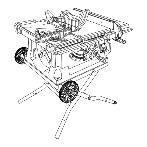
Page 10: Know Your Table Saw
FEATURES KNOw yOUR TAbLE SAw HEIGHT/bEVEL ADJUSTING HANDwHEEL - Located on the front of the cabinet, use this handwheel to lower and raise See Figure 2. the blade for height adjustments or blade replacement. This The safe use of this product requires an understanding of handwheel also makes the adjustment for bevel angles. -
Page 11: Operating Components
FEATURES OPERATING COMPONENTS wARNING: The upper portion of the blade projects up through the table and is surrounded by an insert called the throat plate. The Always remove the switch key when the tool is not in height of the blade is set with a handwheel on the front of the use and keep it in a safe place. -
Page 12: Tools Needed
FEATURES bLADES wARNING: For maximum performance, it is recommended that you use the 10 in. carbide-tipped combination blade provided with Do not use blades rated less than the speed of this tool. your saw. Additional blade styles of the same high quality are Failure to heed this warning could result in personal available for specific operations such as ripping. -
Page 13: Loose Parts
LOOSE PARTS The following items are included with your table saw: Fig. 5 A. Rip Fence ..................................1 B. Large Blade Wrench ..............................1 C. Small Blade Wrench ..............................1 D. Miter Fence with Lock Knob ............................1 E. Switch Key .................................. 1 F. -
Page 14: Assembly
ASSEMbLy UNPACKING wARNING: This product requires assembly. Carefully remove the tool and any accessories from the Never stand directly in line with the blade or allow hands box. Place it on a level work surface. to come closer than 3 in. to the blade. Do not reach over NOTE: This tool is heavy. - Page 15 ASSEMbLy TO ATTACH THE LEG Flat See Figure 7. Flat WasHer sleeVe WasHer NOTE: The leg with the leveling foot should be installed on the front of the saw, right side. Stand the table saw on end as shown in figure 7. ...
- Page 16 ASSEMbLy TO OPEN/CLOSE (SET-UP/TEAR DOwN) THE set-uP tear doWn LEG STAND See Figure 9. To open (set-up) the leg stand: Step 1: With the saw table on end and standing to the side, use your left hand to pull the leg stand latch towards you. ...
- Page 17 ASSEMbLy TO MOVE THE LEG STAND See Figure 10. Holding the leg stand firmly, pull the leg stand toward you until the leg stand and saw are balanced on the wheels. Push the saw to the desired location then either open the leg stand for immediate saw operation or store the saw in a dry environment.
-
Page 18: To Check Saw Blade Installation
ASSEMbLy TO CHANGE RIVING KNIFE POSITIONS See Figure 13. release This saw is shipped with a riving knife that should be placed leVer in the “down” position for non-through cutting and must be (unlocked) placed in the “up” position for all other cutting operations. ... -
Page 19: Blade Guard
ASSEMbLy To tighten the blade: larGe Using the blade wrench, place the flat open end into the Blade WrencH flats on the arbor shaft. Insert the closed end of the blade wrench over the blade nut. Holding both wrenches firmly, push the wrench (left side) to the back of the machine. -
Page 20: Saw Blade
ASSEMbLy TO CHECK AND ALIGN THE RIVING KNIFE AND SAw bLADE See Figure 18. To check alignment of the riving knife: Unplug the saw. Raise the saw blade by turning the height/bevel adjusting handwheel clockwise. Remove the anti-kickback pawls and blade guard correct assembly. -
Page 21: Assembly
ASSEMbLy TO STORE PUSH STICK See Figure 19. PusH stick Insert screws into the holes on the right side of the saw Fence table. Tighten securely. Place the slots in the push stick over the screws and slide the push stick toward the back of the saw. -
Page 22: Operation
OPERATION Kickback can be caused by any action that pinches the wARNING: blade in the wood such as: Making a cut with incorrect blade depth Do not allow familiarity with tools to make you careless. Remember that a careless fraction of a second is suf- ... -
Page 23: Cutting Aids
OPERATION CUTTING AIDS See Figure 22. Push sticks are devices that may be used for pushing a workpiece through the blade in any rip cut. When making PusH sticks non-through cuts or ripping narrow stock, always use a push stick, push block, and/or featherboard so your hands do not come within 3 inches of the saw blade. -
Page 24: Types Of Cuts
OPERATION TyPES OF CUTS See Figure 25. There are six basic cuts: 1) the cross cut, 2) the rip cut, 3) the miter cut, 4) the bevel cross cut, 5) the bevel rip cut, and 6) the compound (bevel) miter cut. All other cuts are combina- tions of these basic six. -
Page 25: How To Make A Featherboard
OPERATION FEATHERbOARD featherboard. Positioning the featherboard will depend on the placement of the bolt and the position of the sliding A featherboard is a device used to help control the miter table on the rails. Place the washer on the bolt and workpiece by guiding it securely against the table or fence. - Page 26 OPERATION TO CHANGE bLADE DEPTH Gullet See Figure 28. The blade depth should be set so that the outer points of the blade are higher than the workpiece by approximately 1/8 in. to 1/4 in. but the lowest points (gullets) are below the top surface.
-
Page 27: To Check Miter Base Parallelism
OPERATION TO CHECK MITER bASE PARALLELISM See Figures 32 - 33. Unplug the saw. Set saw up as if you were preparing to make a cut. Tighten rail clamps, miter locking clamps, lock knob, etc. Slide miter table (A) to the front of miter base (B) as far as it will go. - Page 28 OPERATION TO CHECK MITER FENCE ALIGNMENT See Figure 34. The miter fence must be perpendicular to the blade when set at zero degrees. Set the miter fence (H) at 0°. Miter indicator (I) should be set precisely on 0° and secured in place with adjusting clamp (J).
- Page 29 OPERATION wARNING: Fence To reduce the risk of injury, always make sure the rip fence Blade is parallel to the blade before beginning any operation. TO SET THE RIP FENCE SCALE INDICATOR TO THE bLADE See Figure 36. Begin with the blade at a zero angle (straight up). ...
- Page 30 OPERATION TO USE OUTFEED SUPPORT See Figure 38. The outfeed support slides to give the operator additional support for cutting long workpieces. With the table saw in the OFF position, stand behind the saw. Grasp the outfeed support with both hands and pull it until it is fully extended.
- Page 31 OPERATION HEELING (PARALLELING) THE bLADE See Figures 40 - 41. wARNING: FraminG The blade must be square so the wood does not bind square resulting in kickback. Failure to do so could result in serious personal injury. Do not loosen any bolts for this adjustment until you have checked with a square and made test cuts to be sure adjust- ments are necessary.
-
Page 32: Making Cuts
OPERATION MAKING CUTS cross cut The blade provided with the saw is a high-quality combina- Place leFt Hand on tion blade suitable for ripping and cross cut operations. WorkPiece and miter Fence Here wARNING: Do not use blades rated less than the speed of this tool. Failure to heed this warning could result in personal injury. - Page 33 OPERATION MAKING A RIP CUT riP cut See Figure 44. wARNING: Blade Fence Make sure the blade guard assembly is installed and scale working properly to avoid serious possible injury. Remove the miter fence. Set the blade to the correct depth for the workpiece. ...
- Page 34 OPERATION MAKING A bEVEL CROSS CUT Lock the bevel locking lever. See Figures 46 - 47. Set the blade to the correct depth for the workpiece. Position the rip fence the desired distance from the blade wARNING: for the cut and securely lock the handle.
- Page 35 OPERATION When ripping a long workpiece, place a support the same BeVel riP cut height as the table surface behind the saw for the cut work. Blade Fence Turn the saw on. anGled scale Position the workpiece flat on the table with the edge flush against the rip fence.
- Page 36 OPERATION MAKING A LARGE PANEL CUT larGe Panel cut See Figure 50. Make sure the saw is properly secured to a work surface to riP Fence avoid tipping from the weight of a large panel. wARNING: Make sure the blade guard assembly is installed and working properly to avoid possible serious injury.
- Page 37 OPERATION MAKING A DADO CUT non-tHrouGH cut See Figure 52. Blade An optional dado throat plate is required for this procedure Guard remoVed (see the Accessories section of this manual and check with the retailer where the table saw was purchased). All blades and dado sets must not be rated less than the speed of this tool.
-
Page 38: Adjustments
ADJUSTMENTS Blade wARNING: WrencH Before performing any adjustment, make sure the tool is unplugged from the power supply and the switch is in the OFF position. Failure to heed this warning could result in serious personal injury. Blade The table saw has been adjusted at the factory for making WrencH very accurate cuts. - Page 39 ADJUSTMENTS TO SET THE bLADE AT 0° AND 45° See Figures 56 - 57. 0° adJustment Blade comBination The angle settings of the saw have been set at the factory Bolt square and, unless damaged in shipping, should not require set- ting during assembly.
-
Page 40: Adjustments
ADJUSTMENTS TO CHECK THE ALIGNMENT OF THE RIP FENCE TO THE bLADE riP Fence Blade See Figure 58. screWs Unplug the saw. Raise the locking lever to permit the rip fence to be moved. Place a framing square beside the blade and move the rip fence up to the square. -
Page 41: Maintenance
MAINTENANCE wARNING: wARNING: When servicing, use only identical replacement parts. Do not at any time let brake fluids, gasoline, petroleum- Use of any other parts may create a hazard or cause based products, penetrating oils, etc., come in contact product damage. with plastic parts. -
Page 42: Troubleshooting
TROUbLESHOOTING PRObLEM CAUSE SOLUTION Cutting binds or burns work. Blade is dull. Replace or sharpen blade. Work is fed too fast. Slow the feed rate. Wood is warped. Replace the wood. Always cut with convex side to table surface. Rip fence is misaligned. Check and adjust the rip fence. - Page 43 TROUbLESHOOTING PRObLEM CAUSE SOLUTION Excess vibration. Blade is out of balance. Replace blade. Blade is damaged. Replace blade. Saw is not mounted securely. Tighten all hardware. Work surface is uneven. Reposition on flat surface. Adjust legs of leg stand. Blade is warped. Check saw blade installation.
-
Page 44: Parts And Service
HOW TO OBTAIN CUSTOMER OR TECHNICAL SUPPORT: To obtain Customer or Technical Support please contact us at 1-800-525-2579. RYOBI is a registered trademark of Ryobi Limited and is used pursuant to a license granted by Ryobi Limited. ONE wORLD TECHNOLOGIES, INC.