Table of Contents
Advertisement
Quick Links
Download this manual
See also:
Service Manual
Advertisement
Table of Contents

Related Manuals for NCR 7193


Summary of Contents for NCR 7193
- Page 1 NCR 7193 Thermal Receipt Printer Owner’s Guide BD20-1439-A Issue B August 1998...
- Page 2 NCR, therefore, reserves the right to change specifications without prior notice. All features, functions, and operations described herein may not be marketed by NCR in all parts of the world. In some instances, photographs are of equipment prototypes. Therefore, before using this document, consult with your NCR representative or NCR office for information that is applicable and current.
-
Page 3: Table Of Contents
7193 Owner’s Guide Contents Contents Chapter 1: About the 7193 Printer Models ............................1 Communication Interfaces....................1 Features ..........................2 Options ..........................2 Thermal Printhead ........................2 Ordering Thermal Paper ......................3 Ordering Other Supplies......................3 Cleaning the Printer........................4 Cleaning the Cabinet ...................... - Page 4 Contents 7193 Owner’s Guide Chapter 4: Diagnostics Level 0 Diagnostics........................25 Level 1 Diagnostics........................26 Setting Data Error and Data Buffer options..............26 Setting Printhead Resistance................... 27 Setting Default Lines per Inch ..................28 Setting Partial Cut Distance .................... 28 Ignoring/Using the Carriage Return................
- Page 5 7193 Owner’s Guide Contents Appendix A: Specifications Features ............................ 81 Reliability ..........................81 Power Requirements....................... 81 Environmental Conditions..................... 82 Dimensions and Weight ......................82 Printing Specifications ......................82 Print Zones ..........................83 Density of Receipt Print Lines ....................84 Duty Cycle Restrictions (Printing Solid Blocks)..............84 Appendix B: Print Characteristics Character Size ..........................
- Page 6 Contents 7193 Owner’s Guide August 1998...
-
Page 7: Chapter 1: About The 7193 Printer
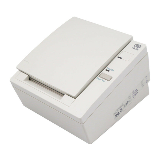
Chapter 1: About the 7193 Printer Chapter 1: About the 7193 Printer The 7193 thermal receipt printer is fast (at 1020 lines per minute), quiet, and very reliable. With thermal printing technology, there is no ribbon cassette to change, and paper loading is extremely simple. -
Page 8: Features
Communication cable Thermal Printhead The 7193 uses a thermal printhead for printing receipts, and it is extremely fast and quiet. Since it uses heat to print directly on paper, there is no cassette or ribbon to change, eliminating soiled fingers and paper dust. -
Page 9: Ordering Thermal Paper
The paper must not be attached at the core. Use paper with a colored stripe at the end to indicate that the paper is running low. To order thermal receipt paper, contact your sales representative or order from NCR at the following address or toll free number:... -
Page 10: Cleaning The Printer
Chapter 1: About the 7193 Printer 7193 Owner’s Guide Cleaning the Printer There is no customer maintenance required for the 7193. Cleaning the Cabinet Clean the cabinet as needed to remove dust and finger marks. Use any household cleaner made for plastics, but test it first on a small unseen area. If the receipt paper bucket is dirty, wipe it with a clean, damp cloth. -
Page 11: Chapter 2: Setting Up The Printer
Installation report card (please complete this form and return to NCR) 7193 Thermal Receipt Printer: Setup and User’s Guide These items may be ordered as options from NCR and will be shipped separately: Wall-mount kit for the printer Communication cable (from host computer to printer) Cash drawer with cables (may be ordered from other equipment suppliers: see “Ordering Other Supplies”... -
Page 12: Repacking The Printer
Be prepared to answer questions concerning shipping and billing. Choosing a Location The 7193 is compact and requires little counter space. It may even be mounted on a wall if space is at a premium. See “Mounting the Printer on a Wall” later in this chapter. The power supply may also be mounted on a wall or under a table. - Page 13 Use a paper clip or other pointed object to set the switch. For additional information on the setup mode (Level 1 Diagnostics), see chapter 4. Note: Some 7193 models may appear slightly different than what is shown in the illustration. The procedures are the same for all models unless otherwise noted.
-
Page 14: Connecting Cash Drawer Cables
If only one cash drawer is used, plug the cable into the connector labeled 1. Note: Some 7193 models may appear slightly different than what is shown in the illustration. The procedures are the same for all models unless otherwise noted. -
Page 15: Connecting Communication And Power Cables
7193 Owner’s Guide Chapter 2: Setting Up the Printer Connecting Communication and Power Cables The printer uses separate cables for communicating with the host computer and receiving power from the power supply. Caution: Be sure that all power is disconnected before connecting the cables. -
Page 16: Parallel Models
Chapter 2: Setting Up the Printer 7193 Owner’s Guide Parallel Models August 1998... -
Page 17: Turning On The Printer
7193 Owner’s Guide Chapter 2: Setting Up the Printer Turning On the Printer Note: The operator panel may differ from the standard version (left) depending on the model. On models matching the alternate version (right), use a paper clip or pointed object to press the plunger to put the printer on- or off-line. -
Page 18: Loading And Changing Paper
7193 Owner’s Guide Loading and Changing Paper The 7193 features extremely simple paper loading. See the next two illustrations. If you are loading paper for the first time and have already taken the roll out, go to “Putting In the Paper Roll” later in this chapter. If you have not taken the roll out, continue with the following instructions. -
Page 19: Putting In The Paper Roll
7193 Owner’s Guide Chapter 2: Setting Up the Printer Putting In the Paper Roll Before putting in a new roll, tear off the end of the roll so that the edge is loose. August 1998... -
Page 20: Advancing Paper
7193 Owner’s Guide Advancing Paper Note: Some 7193 models may appear slightly different than what is shown in the illustration. The procedures are the same for all models unless otherwise noted. To advance the receipt paper, press the Paper Feed button on the operator panel. -
Page 21: Testing The Printer
7193 Owner’s Guide Chapter 2: Setting Up the Printer Testing the Printer Run this test to check the printer. The test prints the settings for several functions, prints all variations of the character sets, and partially cuts the paper between each variation. See “Level 1 Diagnostics”... - Page 22 Chapter 2: Setting Up the Printer 7193 Owner’s Guide August 1998...
-
Page 23: Mounting The Printer On A Wall
7193 Owner’s Guide Chapter 2: Setting Up the Printer Mounting the Printer on a Wall Use the wall-mount kit to mount the printer vertically on a wall. See “Ordering Other Supplies” in chapter 1 for information on ordering the printer wall-mount kit. - Page 24 Chapter 2: Setting Up the Printer 7193 Owner’s Guide August 1998...
-
Page 25: Mounting The Power Supply On A Wall
7193 Owner’s Guide Chapter 2: Setting Up the Printer Mounting the Power Supply on a Wall The power supply can be ordered with a wall-mount kit to mount the power supply on the wall or under a table. See “Ordering Other Supplies” in chapter 1 for information on ordering the power supply with or without a wall-mount kit. - Page 26 Chapter 2: Setting Up the Printer 7193 Owner’s Guide August 1998...
-
Page 27: Chapter 3: Solving Problems
Chapter 3: Solving Problems Chapter 3: Solving Problems The 7193 printer is a simple, generally trouble-free printer, but from time to time minor problems may occur. For example, the power supply may be interrupted or the printhead may overheat for some reason. -
Page 28: Correcting Problems
Correcting Problems Operator-Correctable Conditions The following conditions can be corrected generally without calling for service. However, if problems persist, contact your NCR authorized service representative to arrange for a service call. Paper Out Replace the paper roll. Do not operate the printer or host computer if the printer runs out of paper. -
Page 29: Contacting A Service Representative
Make sure the power supply is plugged in and that the printer is on-line. Contact your NCR authorized service representative if this does not resolve the problem. Print is Light or Spotty The printhead may be dirty. Clean it with cotton swabs and rubbing alcohol. - Page 30 Chapter 3: Solving Problems 7193 Owner’s Guide August 1998...
-
Page 31: Chapter 4: Diagnostics
7193 Owner’s Guide Chapter 4: Diagnostics Chapter 4: Diagnostics The following diagnostic tests are available for the 7193: Level 0 Diagnostics Performed during the startup cycle Level 1 Diagnostics (setup mode) Available in a dedicated environment and accessed through the DIP Switches... -
Page 32: Level 1 Diagnostics
If the settings are accidentally changed, see the tables in this section to change the settings back. If you need assistance, contact your NCR-authorized service representative. The functions and tests are described in the following order in this section:... -
Page 33: Setting Printhead Resistance
7193 Owner’s Guide Chapter 4: Diagnostics One Line Data Buffer Turn the printer back on to enter the settings into the EEROM. The On Line light (green) blinks. Turn the printer off and set the DIP switches to the former settings. -
Page 34: Setting Default Lines Per Inch
Chapter 4: Diagnostics 7193 Owner’s Guide Setting Default Lines per Inch This function allows you to set the default for lines per inch to either 7.6 or 6. Note: The operator panel may differ depending on the model. To turn the printer on or off, (on-line or off-line), use a paper clip or other pointed object to depress the plunger (in place of the On Line button) on models with that item. -
Page 35: Ignoring/Using The Carriage Return
Ignore CR (Hex 0D) Use CR (Hex 0D) as Print Command (Default)* *Emulates the NCR 7150™ printer. Turn the printer back on to enter the settings into the EEROM. The On Line light (green) blinks. Turn the printer off and set the DIP switches to the former settings. -
Page 36: Running The Data Scope Mode
Chapter 4: Diagnostics 7193 Owner’s Guide DIP switch 1 must be Off to return the printer to the on-line mode. Turn the printer back on. Running the Data Scope Mode This test prints a hexadecimal dump of all data sent to the printer: “1” prints as hexadecimal 31, “A”... -
Page 37: Testing Receipt Printing
7193 Owner’s Guide Chapter 4: Diagnostics Set the switches to the settings in the table. Switch 1 Switch 2 Switch 3 Switch 4 Switch 5 Switch 6 Turn the printer back on to enter the settings into the EEROM and disable the Data Scope Mode. -
Page 38: Level 2 Diagnostics
Chapter 4: Diagnostics 7193 Owner’s Guide Level 2 Diagnostics Level 2 diagnostics run during normal printer operation. When the following conditions occur, the printer automatically turns off the appropriate motors and disables printing to prevent damage: Paper out, cover off, or knife unable to home... -
Page 39: Chapter 5: Communication
Interfaces In order for the printer to communicate with the host, a communication link must be set up. The 7193 supports the following communication interfaces: RS-232C Interface Parallel Interface Each of these has a protocol associated with it that the host must understand and adhere to. -
Page 40: Rs-232C Interface
DIP switches. See “RS-232C Switch Settings” later in this chapter for the switch settings. Print Speed and Timing The faster speed of new 7193 models requires the application to send data to the printer at least as fast as it is printed. The application must also allow receipt lines to be buffered ahead at the printer, so the printer will be able to print each line immediately after the preceding line, without stopping to wait for more data. -
Page 41: Xon/Xoff Protocol
7193 Owner’s Guide Chapter 5: Communication The next table shows that with no delay between lines, the transmit time is much less than the print time, allowing the printer to print at full speed. Characters/Line Lines/Receipt Transmit Time: Transmit Time: (19.2... -
Page 42: Rs-232C Technical Specifications
The connector is a 9-pin male D-shell connector and is located in the hollow cavity under the printer. With RS-232C, the 7193 is always remotely powered. The following illustration shows the power cable connector and pin assignments. The power cable connector is 6-pin mini DIN plug and is located in the small cavity under the printer at the front. - Page 43 7193 Owner’s Guide Chapter 5: Communication RS-232C Printers Pin Number Cash Drawer 1 Connector Cash Drawer 2 Connector Frame Ground Frame Ground Drawer 1 Solenoid Drawer 2 Solenoid (Remove jumper JPR2 to disable) Drawer 1 Status Switch Drawer 2 Status Switch...
- Page 44 Chapter 5: Communication 7193 Owner’s Guide DIP Switch Settings for RS-232C Parameters Switch Settings Description On-line Mode (default) Level 1 Diagnostics (setup mode) DTR/DSR Protocol (default) XON/XOFF Protocol Without Parity (default) With Parity Odd Parity Even Parity 5, 6 19,200 Baud...
-
Page 45: Parallel Interface
7193 Owner’s Guide Chapter 5: Communication Parallel Interface Parallel Protocol The 7193 uses a standard PC-compatible parallel interface. The illustration shows the timing diagram for the interface protocol. D A TA STROBE 0 .5 µ s (M in .) 1 .0 µ s (M in .) 0 .0 8 µ... -
Page 46: Parallel Technical Specifications
Chapter 5: Communication 7193 Owner’s Guide Parallel Technical Specifications Parallel Connectors The following illustration shows the Parallel communication connector and pin assignments. The connector is at the rear of the printer. The connector for the power supply cable has the following pin assignments. The power cable connector is in the small cavity under the printer at the front. - Page 47 7193 Owner’s Guide Chapter 5: Communication The following table shows the pinouts for cash drawers 1 and 2. The cash drawer connectors are located at the rear of the printer. Parallel Printers Pin Number Cash Drawer 1 Connector Cash Drawer 2 Connector...
- Page 48 Chapter 5: Communication 7193 Owner’s Guide August 1998...
-
Page 49: Chapter 6: Commands
Note: All versions of the 7193 use the same commands as listed in this section unless otherwise noted. For example, the Parallel interface requires unique commands for controlling the cash drawer. - Page 50 Chapter 6: Commands 7193 Owner’s Guide Printer Function Commands Hexadecimal Code Command Page Horizontal Tab Line Feed Carriage Return Clear Printer 14 n Feed n Print Lines 15 n Feed n Dot Rows 16 n Add n Extra Dot Rows...
-
Page 51: Print Characteristics Commands
7193 Owner’s Guide Chapter 6: Commands Print Characteristics Commands These commands control what the printed information looks like and are listed in numerical order of their hexadecimal codes. Print Characteristics Commands Hexadecimal Code Command Page Select Double-Wide Characters Select Single-Wide Characters... -
Page 52: Printer Status Commands
Chapter 6: Commands 7193 Owner’s Guide Printer Status Commands These commands send printer status information to the host computer and are listed in numerical order of their hexadecimal codes. Printer Status Commands Hexadecimal Code Command Page 1B 75 0 Transmit Cash Drawer Status (RS-232C Only) -
Page 53: Command Descriptions
7193 Owner’s Guide Chapter 6: Commands Command Descriptions This section lists the commands with their hexadecimal, decimal, and ASCII codes. The commands are grouped in the following categories: Printer Function Commands Print Characteristics Commands Graphics Commands Printer Status Commands Real Time Commands... -
Page 54: Clear Printer
Chapter 6: Commands 7193 Owner’s Guide Clear Printer Clears the print line buffer without printing and sets the printer to the following condition: Double-Wide (12) command is cancelled Line Spacing, Pitch, and User-Defined Character Sets are maintained at current selections (RAM is not affected) -
Page 55: Full Knife Cut
7193 Owner’s Guide Chapter 6: Commands Print Prints one line from the buffer and feeds paper one line. Hexadecimal Decimal ASCII Full Knife Cut This command is implemented the same as Partial Knife Cut (1A/1B 6D). Hexadecimal Decimal ASCII 1B 69... - Page 56 Chapter 6: Commands 7193 Owner’s Guide Set Absolute Starting Position Sets the print starting position to the specified number of dots (up to the right margin) from the beginning of the line. The print starting position is reset to the first column after each line.
-
Page 57: Select Peripheral Device
7193 Owner’s Guide Chapter 6: Commands Select Peripheral Device Selects the device which the host computer sends data to. When the printer is disabled by this command, it ignores transmitted data until the printer is re-enabled by the same command. -
Page 58: Set Relative Starting Position
Chapter 6: Commands 7193 Owner’s Guide Set Relative Starting Position Moves the print starting position the specified number of dots either right (up to the right margin) or left (up to the left margin) of the current position. The print starting position is reset to the first column after each line. -
Page 59: Align Character Positions
7193 Owner’s Guide Chapter 6: Commands Align Character Positions Specifies the alignment of characters, graphics, logos, and bar codes (see table). It is valid only at the beginning of a line. Hexadecimal Decimal ASCII Value of n Default 1B 61 n... -
Page 60: Write To Non-Volatile Memory
Chapter 6: Commands 7193 Owner’s Guide Write to Non-Volatile Memory Writes two-byte word n1:n2 to location k in history EEROM. Hexadecimal Decimal ASCII Value of n Value of k 1B 73 27 115 ESC s n1 = 1st Byte 16-63 (Hex Locations... - Page 61 The default horizontal motion is x = 150. Before this command was implemented on the 7193, the default horizontal motion unit was also x = 150, except for graphics. The default for graphics was x = 1/300 inch when using the Set Absolute Starting Postion command (1B 24) and Set Relative Starting Position command (1B 5C).
-
Page 62: Print Characteristics Commands
Chapter 6: Commands 7193 Owner’s Guide Set Printing Area Width Sets the width of the printing area. The command is effective only at the beginning of a line. Hexadecimal Decimal ASCII Value of nL Value of nH 0-255 0-255 1D 57 nL nH... -
Page 63: Select Single-Wide Characters
7193 Owner’s Guide Chapter 6: Commands Select Single-Wide Characters Prints single-wide characters. It may be used with double-wide characters on the same line, but not with Single and Double Density Graphics modes. Hexadecimal Decimal ASCII Rotate Characters Counter-Clockwise Rotates characters 90 degrees counter-clockwise. It remains in effect until the printer is reset or until a Clear Printer (10), Set/Cancel Upside-Down Print (1B 7B), or Set/Cancel Rotated Print (1B 56) command is received. -
Page 64: Select Character Set
Chapter 6: Commands 7193 Owner’s Guide Select Character Set Selects the character set. The character sets cannot be used together on the same line. When an undefined RAM character is selected, the Code Page 437 character is used. See “Appendix B” for the character sets. -
Page 65: Cancel User-Defined Character
7193 Owner’s Guide Chapter 6: Commands Copy Character Set from ROM to RAM Copies characters in the active ROM set to RAM. Use it to modify characters in one of the character set variations, such as Rotated Print. Select one of the Rotated Print commands, copy to RAM, then use the command, Define User-Defined Character Set (1B 26). -
Page 66: Graphics Commands
448. The print starting position is reset to column one after each line. This command emulates the Epson LQ-950™ dot matrix printer. This allows the 7193 to accept graphics that are normally output from word processing programs to a half-dot matrix printer. -
Page 67: Set Bit Image Mode
7193 Owner’s Guide Chapter 6: Commands Note: If the Set Horizontal and Vertical Minimum Motion Units command (1D 50) is used to change the horizontal and vertical minimum motion unit, the parameters of this command (Set Absolute Starting Position) will be interpreted accordingly. For more information, see the description of the Set Horizontal and Vertical Minimum Motion Units command earlier in this chapter. -
Page 68: Single-Density Graphics
Chapter 6: Commands 7193 Owner’s Guide 24-Dot Single-Density Mode Top of Bit Image d4 d7 Single-Density Graphics Enters one line of 8-dot single-density graphics into the print buffer. Any print command is required to print the line, after which the printer returns to normal processing mode. When the print buffer is full, incoming data will be accepted but not printed. -
Page 69: Printer Status Commands
7193 Owner’s Guide Chapter 6: Commands Define Downloaded Bit Image Enters a downloaded bit image (such as a logo) into RAM with the number of dots specified by n1 and n2. It is available until power is turned off, another bit image is defined, or either Initialize Printer (1B 40), or Define User-Defined Character Set (1B 26), command is received. -
Page 70: Printer Status Commands
Chapter 6: Commands 7193 Owner’s Guide Printer Status Commands For RS-232C printers, these commands enable the printer to communicate with the host computer following the selected handshaking protocol, either DTR/DSR or XON/XOFF. They are stored in the printer’s data buffer as they are received, and are handled by the firmware in the order in which they were received. - Page 71 7193 Owner’s Guide Chapter 6: Commands Transmit Printer Status Sends status data to the host computer. This command is available only on RS-232C printers. Hexadecimal Decimal ASCII 1B 76 27 118 ESC v The printer sends one byte to the host computer when it is not busy or in a fault condition.
- Page 72 Chapter 6: Commands 7193 Owner’s Guide Type ID (n = 2) Off/On Decimal Function No two-byte character code installed. Two-byte character code installed. No knife installed. Knife installed. Undefined. Undefined. Not used. Fixed to Off. Undefined Undefined Not used. Fixed to Off.
- Page 73 7193 Owner’s Guide Chapter 6: Commands Off/On Decimal Status for ASB Cash drawer status disabled. Cash drawer status enabled. RS-232C Busy status disabled. RS-232C Busy status enabled. Error status disabled. Error status enabled. Receipt paper roll status disabled. Receipt paper roll status enabled.
- Page 74 Chapter 6: Commands 7193 Owner’s Guide Not used. Fixed to off. Second Byte (Error information) Off/On Decimal Status for ASB Undefined Undefined Undefined No knife error. Knife error occurred. Not used. Fixed to off. No unrecoverable error. Unrecoverable error occurred.
- Page 75 7193 Owner’s Guide Chapter 6: Commands Transmit Status Transmits the status specified by n. This command is a batch mode command; that is, the response is transmitted after all prior data in the receive buffer has been processed. There may be a time lag between the printer receiving this command and transmitting the response, depending on the receive buffer status.
-
Page 76: Real Time Commands
An application using these GS (Hex 1D) sequences does not need to distinguish for the printer between the new Real Time commands and the old Clear Printer command. This implementation is ideal for an existing 7193 application which already uses the Clear Printer command or for a new application being developed. -
Page 77: Alternate Implementation
U950™ application which is being migrated to a 7193. This application would not be using the 7193 Clear Printer command at all since it is not recognized by the Epson printers. Note: The DLE (Hex 10) sequences as implemented on Epson’s TM-T85™ and TM-U950™... - Page 78 Now if the cover is open or the paper is exhausted, the 7193 printer will still accept data, respond to the batch mode status commands (ESC v and ESC u), handle the cash drawer commands, and not go busy until it actually tries to execute a print command.
- Page 79 7193 Owner’s Guide Chapter 6: Commands If you have programmed the printer to handle the busy line the old way, but wish to re- program it to the new way, do the following steps: August 1998...
- Page 80 Chapter 6: Commands 7193 Owner’s Guide Record the current switch settings for their RS-232C parameters. Set switches 2, 3, and 6 to OFF, and set switches 1, 4, and 5 to ON. Power cycle the printer. Wait until the printer beeps to store the parameter change in NVRAM.
- Page 81 7193 Owner’s Guide Chapter 6: Commands Fixed to On. 2 = Transmit RS-232C Busy Status Status Decimal Function Fixed to Off. Fixed to On. Both receipt and cassette doors closed. Receipt or cassette door open. Paper feed button is not pressed.
- Page 82 Chapter 6: Commands 7193 Owner’s Guide Receipt paper exhausted Fixed to Off Real Time Request to Printer The printer responds to a request from the host specified by n. The operations performed depend on the value of n, according to the following parameters.
- Page 83 Error condition exists in the printer. Fixed to On. 7193 Clear Printer Command Resets certain parameters and clears the print buffer as originally defined. This is NOT a Real Time command. It only distinguishes the Clear Printer command from other DLE sequences.
-
Page 84: Bar Code Commands
Chapter 6: Commands 7193 Owner’s Guide Batch Mode Response Response Recognized By: ESC u 0 Binary ESC v Binary Binary GS I n GS r n Binary Real Time Response Response Recognized By: GS EOT n Binary Binary DLE EOT n... -
Page 85: Select Pitch Of Hri Characters
7193 Owner’s Guide Chapter 6: Commands Select Pitch of HRI Characters This command is not implemented and is ignored if received. Hexadecimal Decimal ASCII Value of n (Pitch) Default 1D 66 n 29 102 n GS f n 0 = Standard Pitch at CPI... - Page 86 Chapter 6: Commands 7193 Owner’s Guide Bar Code n, Length UPC-A 48- 57 (ASCII numerals) Fixed Length: 11, 12 UPC-E 48- 57 Fixed Length: 11, 12 JAN13 (EAN) 48- 57 Fixed Length: 12, 13 JAN8 (EAN) 48- 57 Fixed Length: 7,8...
- Page 87 7193 Owner’s Guide Chapter 6: Commands Bar Code n, Length UPC-A 48- 57 (ASCII numerals) Fixed Length: 11, 12 UPC-E 48- 57 Fixed Length: 11, 12 JAN13 (EAN) 48- 57 Fixed Length: 12, 13 JAN8 (EAN) 48- 57 Fixed Length: 7, 8...
- Page 88 Chapter 6: Commands 7193 Owner’s Guide August 1998...
-
Page 89: Appendix A: Specifications
Electronics: 240,000 Hours of Ontime Knife: 1 Million Cuts Power Requirements The 7193 printer receives power from a separate in-line power supply which can be purchased separately. Power from Power Supply (Remote) Voltage: 24 Vdc +5 Volt Supply for the Logic Circuits... -
Page 90: Environmental Conditions
Appendix A: Specifications 7193 Owner’s Guide Environmental Conditions Operating Temperature: 5°C to 35°C (40°F to 95°F), models with no knife 5°C to 28°C (41°F to 82°F), models with knife Operating Humidity: 5% to 90% Note: The printer can operate at higher temperatures if the humidity is lower (5°C to 45°C with humidity of 5% to 35%). -
Page 91: Print Zones
7193 Owner’s Guide Appendix A: Specifications Print Zones The printer centers characters (standard pitch and compressed pitch) and graphics on an 80 mm wide (3.15 in.) receipt. Standard pitch: 10 x 18 dots in character cell, 44 characters (columns) per line... -
Page 92: Duty Cycle Restrictions (Printing Solid Blocks)
7193 Owner’s Guide Density of Receipt Print Lines When the 7193 prints high density print lines (text or graphics), it automatically slows down to a rate slower than 1020 lines per minute. High density print lines are defined as lines with over 57% of the dots printing on the line (there are 448 total dot columns on the print station). -
Page 93: Character Size
7193 Owner’s Guide Appendix B: Print Characteristics Appendix B: Print Characteristics Character Size The following two illustrations show the dot patterns of sample characters for standard pitch (15.2 CPI) and compressed pitch (19 CPI). August 1998... -
Page 94: Code Page 437 Character Set
Appendix B: Print Characteristics 7193 Owner’s Guide Code Page 437 Character Set These are the characters for the Code Page 437 character set. August 1998... -
Page 95: Code Page 850 Character Set
7193 Owner’s Guide Appendix B: Print Characteristics Code Page 850 Character Set These are the characters for the Code Page 850 character set. August 1998... - Page 96 Appendix B: Print Characteristics 7193 Owner’s Guide August 1998...
- Page 97 7193 Owner’s Guide Index Index Carriage return —7— ignoring/using, 29 7193 printer Cash drawer cleaning, 4 connector and pin assignments, 36, 40 clearance, 6 ordering, 3 description, 1 Cash drawer cable dimensions, 6, 82 connecting, 8 environmental conditions, 82 Changing paper, 12...
- Page 98 32 transmit status, 46, 69 receipt cover open, 32 Commands, real time startup, 25 7193 clear printer command, 76 Dimensions, of printer, 6, 82 alternate implementation, 71 DIP switches. See Switch settings first implementation, 70 moving data through the buffer, 71...
- Page 99 7193 Owner’s Guide Index number of operating hours, 32 Lights —E— indicating problems, 21 Environmental conditions, 82 Lines per inch Errors. See Problems default, 28 Lines printed —F— number of, 32 Loading paper, 12 Features, 2, 81 Location choosing, 6 —I—...
- Page 100 Index 7193 Owner’s Guide parameters, 41 protocol, 39 technical specifications, 40 Partial cut distance setting, 28 —R— Pitch of characters Receipt cover 15.2 cpi, 85 open, 32 19 cpi, 85 receipt printing Power test, 31 turning on the printer, 11...
- Page 101 7193 Owner’s Guide Index Troubleshooting. See Problems Turning on the printer, 11 —V— Voltage low or high, 32 —T— Tallies. See Level 3 diagnostics —W— Technical specifications Wall-mount kit parallel interface, 40 power supply, 5, 19 RS-232C interface, 36 printer, 4, 5, 17...
- Page 102 Index 7193 Owner’s Guide August 1998...
- Page 104 BD20-1439-A Issue B 0898 NCR is the name and mark of NCR Corporation © 1997 NCR Corporation Printed in U.S.A.