Dell OptiPlex GX260 Series System User's Manual
Hide thumbs
Also See for OptiPlex GX260 Series:
- Service manual (100 pages) ,
- User manual (31 pages) ,
- Disassembly (27 pages)
Table of Contents
Advertisement
Dell™ OptiPlex™ GX260 Systems User's Guide
Documentation for Your
Computer
Finding Information for Your Computer
Technical Specifications
System Board Components
Cleaning Your Computer
Small Form-Factor Computer
About Your Computer
Front View
Back View
Inside Your Computer
Attaching and Removing the Computer
Stand
Adding and Removing Parts
Opening the Computer Cover
AGP and DVI Adapter Cards
Battery
Memory
PCI Cards and Serial Port Adapters
Drives
Microprocessor
Telephony Applications Programming
Interface (TAPI)
Closing the Computer Cover
Small Desktop Computer
About Your Computer
Front View
Back View
Inside Your Computer
Attaching and Removing the Computer
Stand
Adding and Removing Parts
Opening the Computer Cover
AGP and DVI Adapter Cards
Battery
Drives
Memory
Microprocessor
PCI Cards and Serial Port Adapters
Telephony Applications Programming
Interface (TAPI)
Closing the Computer Cover
Advanced Features
LegacySelect Technology Control
Manageability
Security
Password Protection
System Setup
Jumper Settings
Power Button
Hyper-Threading
Advertisement
Table of Contents

Related Manuals for Dell OptiPlex GX260 Series


Summary of Contents for Dell OptiPlex GX260 Series
-
Page 1: Small Desktop Computer
Dell™ OptiPlex™ GX260 Systems User's Guide Documentation for Your Advanced Features Computer LegacySelect Technology Control Manageability Finding Information for Your Computer Security Technical Specifications Password Protection System Board Components System Setup Cleaning Your Computer Jumper Settings Power Button Hyper-Threading Small Form-Factor Computer... -
Page 2: Notes, Notices, And Cautions
Corporation; NetWare and Novell are registered trademarks of Novell, Inc. ENERGY STAR is a registered trademark of the U.S. Environmental Protection Agency. As an ENERGY STAR partner, Dell Computer Corporation has determined that this product meets the ENERGY STAR guidelines for... - Page 3 Other trademarks and trade names may be used in this document to refer to either the entities claiming the marks and names or their products. Dell Computer Corporation disclaims any proprietary interest in trademarks and trade names other than its own.
-
Page 4: Finding Information For Your Computer
Back to Contents Page Finding Information for Your Computer Dell™ OptiPlex™ GX260 Systems User's Guide What Are You Looking Find It Here For? ResourceCD A diagnostic program for my computer Drivers for my computer My computer documentation My device documentation... - Page 5 Top technical issues for my computer Frequently asked questions File downloads The Dell Premier Support website is customized for corporate, government, and education Details on my customers. This site may not be available in all regions. computer's configuration Service contract for...
-
Page 7: Technical Specifications
Back to Contents Page Technical Specifications Dell™ OptiPlex™ GX260 Systems User's Guide Microprocessor Ports Memory Key Combinations Computer Information Controls and Lights Audio Power Expansion Bus Physical Drives Environmental Microprocessor Microprocessor type Intel® Pentium® 4 and Celeron™ microprocessors. Design provides for future Dell-supported upgrades. - Page 8 Network interface controller integrated PCI Network Interface with ASF (Alert Standards Format) support as defined by DMTF. Audio Audio type AC97, Sound Blaster emulation Audio controller Integrated AC97 Codec Stereo conversion 16-bit analog-to-digital; 20-bit digital-to- analog Interfaces: Internal PCI bus/AC97 External stereo line-in minijack, microphone-in minijack, line-out minijack on the rear...
- Page 9 drives Internally accessible bays: Small form-factor computer one bay for a 1-inch-high IDE hard drive Small desktop computer one bay for a 1-inch-high IDE hard drive Small mini-tower computer two bays for a 1-inch high IDE hard drive Ports Externally accessible: Serial (data terminal equipment one 9-pin connector;...
- Page 10 only) Controls and Lights Power control push button Power lights green light on power button—blinking green in sleep state; solid green for power on state Hard drive access light green light Link integrity light (on integrated network green light for 10-Mb operation; orange adapter) light for 100-Mb operation;...
- Page 11 Temperature: Operating 10° to 35°C (50° to 95°F) Storage –40° to 65°C (–40° to 149°F) Relative humidity 20% to 80% (noncondensing) Maximum vibration: Operating 0.25 gravities (G) at 3 to 200 Hz at 0.5 octave/min Storage 0.5 G at 3 to 200 Hz at 1 octave/min Maximum shock: Operating bottom half-sine pulse with a change in...
-
Page 12: System Board Components
Back to Contents Page System Board Components Dell™ OptiPlex™ GX260 Systems User's Guide System Board 12 CD drive audio cable connector (CD_IN) floppy drive connector (DSKT) 13 telephony connector (MODEM) internal speaker (SPEAKER) battery socket (BATTERY) 14 power connector (12VPOWER) - Page 13 AGP card connector (AGP) 20 RTC reset jumper (RTCRST) 10 PCI card connectors (PCI1, PCI2, PCI3, and PCI4) 21 password jumper (PSWD) 11 front-panel audio cable connector (FRONTAUDIO) Back to Contents Page...
-
Page 14: Cleaning Your Computer
Back to Contents Page Cleaning Your Computer Dell™ OptiPlex™ GX260 Systems User's Guide Computer, Keyboard, and Monitor Mouse Floppy Drive CDs and DVDs CAUTION: Before you begin any of the procedures in this section, follow the steps in "CAUTION: Safety Instructions."... -
Page 15: Floppy Drive
6. Replace the ball and retainer ring. Turn the retainer ring clockwise until it clicks into place. Floppy Drive NOTICE: Do not attempt to clean drive heads with a swab. You might accidentally misalign the heads, which prevents the drive from operating. Clean your floppy drive using a commercially available cleaning kit. -
Page 16: Advanced Features
LegacySelect Technology Control LegacySelect technology control offers legacy-full, legacy-reduced, or legacy-free solutions based on common platforms, hard-drive images, and help desk procedures. Control is provided to the administrator through system setup, Dell OpenManage™ IT Assistant, or Dell™ custom factory integration. -
Page 17: Dell Openmanage It Assistant
Used in conjunction with IT Assistant, OMCI allows customers to remotely perform remote BIOS updates and modify CMOS settings on a single Dell system or a group of Dell systems. -
Page 18: Padlock Ring And Security Cable Slot
Before you purchase an antitheft device, make sure that it works with the security cable slot on your computer. Antitheft devices usually include a segment of metal-stranded cable with an attached locking device and key. Dell recommends that you use a Kensington lock. The documentation that comes with the device contains instructions for installing it. -
Page 19: Typing Your System Password
2. Highlight System Password and then press the left- or right-arrow key. The option heading changes to Enter Password, followed by an empty 32-character field in square brackets. 3. Type your new system password. You can use up to 32 characters. To erase a character when entering your password, press <Backspace> or the left- arrow key. -
Page 20: Assigning A Setup Password
3. When prompted, type the system password. 4. Press <Ctrl><Enter> to disable the existing system password. 5. Confirm that Not Enabled is displayed for the System Password option. If Not Enabled is displayed, the system password is deleted. If Not Enabled is not displayed, press <Alt><b> to restart the computer, and then repeat steps 3 through 5. -
Page 21: Disabling A Forgotten Password And Setting A New Password
To change an existing setup password, you must know the setup password. 1. Enter system setup. 2. Type the setup password at the prompt. 3. Highlight Setup Password and press the left- or right-arrow key to delete the existing setup password. The setting changes to Not Enabled. -
Page 22: Entering System Setup
Dell recommends that you print the system setup screens (by pressing <Print Screen>) or record the information for future reference. Before you use system setup, you must know the kind of floppy drive(s) and hard drive(s) installed in your computer. To confirm this information, see the Manufacturing Test Report that came with your computer, or find this information in the online Dell Accessories folder. -
Page 23: Changing Boot Sequence For The Current Boot
Changing Boot Sequence for the Current Boot You can use this feature, for example, to tell the computer to boot from the CD drive so you can run the Dell Diagnostics, but specify that the computer boots from the hard drive when the diagnostic tests are complete. -
Page 24: Changing Boot Sequence For Future Boots
1. Turn on or restart your computer. 2. When F2 = Setup appears in the upper-right corner of the screen, press <F12>. The Boot Device Menu appears, listing all available boot devices. Each device has a number next to it. At the bottom of the menu, enter the number of the device that is to be used for the current boot only. -
Page 25: Integrated Devices
Diskette Drive A (the boot floppy drive) is the 3.5-inch floppy drive installed in the top externally accessible drive bay. The two options are 3.5 Inch, 1.44 MB, and Not Installed. Tape drives are not reflected in the Diskette Drive A option. For example, if a single floppy drive and a tape drive are attached to the floppy drive interface cable, set Diskette Drive A to 3.5 Inch, 1.44 MB. -
Page 26: Jumper Settings
1. Restart your computer. 2. As the system restarts, press <F2> to enter system setup. 3. When the system setup screen appears, press <Alt><F> to load the Dell default settings. The computer beeps when the settings are restored. 4. Verify that the time, date, and year are correct and that the Secondary Drive 0 option is set to Auto. -
Page 27: Power Button
NOTICE: Ensure that your computer is turned off and unplugged before you change the jumper settings. Otherwise, damage to your computer or unpredictable results can occur. To change a jumper setting, pull the plug off its pin(s) and carefully fit it down onto the pin(s) indicated. System Board Jumper Settings Jumper Setting... -
Page 28: Hyper-Threading
3. In the Device Manager window, click the plus (+) sign next to the processor type. If Hyper-Threading is enabled, the processor is listed twice. You can enable or disable Hyper-Threading through system setup. For more information on Hyper-Threading, search the Knowledge Base on the Dell Support website at support.dell.com. Back to Contents Page... -
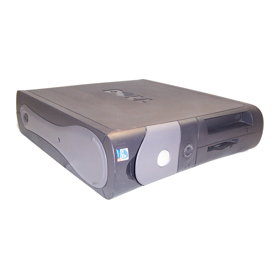
Page 30: About Your Computer
Back to Contents Page About Your Computer Dell™ OptiPlex™ GX260 Systems User's Guide Front View Back View Inside Your Computer Attaching and Removing the Computer Stand Front View Small Form-Factor Computer 1 USB Connect USB devices such as a mouse, keyboard, printer, joystick, and computer speakers into any of the connectors USB connectors. - Page 31 Plug a standard mouse into the green mouse connector. Turn off the computer and any attached devices connector before you connect a mouse to the computer. If you have a USB mouse, plug it into a USB connector. If your computer is running Windows 2000 or Windows XP, Dell installed the necessary mouse drivers on...
-
Page 32: Inside Your Computer
UTP cable into the network adapter connector until the cable snaps securely into place. Dell recommends the use of Category 5 wiring and connectors for our customers' networks. network The yellow light flashes when the computer is transmitting or receiving network data. A high volume of activity network traffic may make this light appear to be in a steady "on"... -
Page 33: Attaching And Removing The Computer Stand
1 hard drive 6 system board 2 floppy drive 7 power supply 3 CD/DVD drive 8 padlock ring 4 internal speaker 9 heat sink and blower assembly 5 chassis intrusion switch Cable Colors Hard drive Blue pull tab Floppy drive Black pull tab CD/DVD drive Orange pull tab Attaching and Removing the Computer Stand... - Page 34 1. Place the computer on its right side so that the drive bays are at the bottom. 2. Fit the stand onto what was the left side of the computer. a. Position the stand as shown in the following illustration by aligning the large round hole in the stand with the securing button on the side of the cover and aligning the captive screw in the stand with the screw hole in the cover.
- Page 35 Back to Contents Page Adding and Removing Small Form-Factor Computer Parts Dell™ OptiPlex™ GX260 Systems User's Guide Opening the Computer Cover AGP and DVI Adapter Cards Battery Drives Memory Microprocessor PCI Cards and Serial Port Adapters Telephony Applications Programming Interface (TAPI)
-
Page 36: Opening The Computer Cover
Back to Contents Page Opening the Computer Cover Dell™ OptiPlex™ GX260 Systems User's Guide CAUTION: Before you begin any of the procedures in this section, follow the steps in "CAUTION: Safety Instructions." CAUTION: To guard against electrical shock, always unplug your computer from the electrical outlet before opening the cover. - Page 37 Back to Contents Page...
- Page 38 To guard against electrical shock, always unplug your computer from the electrical outlet before opening the cover. Your Dell™ computer provides a connector for an AGP or DVI adapter card. NOTE: The DVI adapter card works through your computer's integrated graphics. To control the adapter through your operating system, click the Start menu, click Control Panel, and then click the integrated graphics driver's user- interface icon.
- Page 39 Removing the Card 1 card notch 2 card clip lever 3 card clip tab 4 card clip 5 PCI card slot Installing an AGP/DVI Adapter Card 1. To add or replace the card, press the card clip lever toward the PCI card slot and gently press the card into the AGP connector until it clicks into place.
- Page 40 information on resetting the chassis intrusion detector. Back to Contents Page...
- Page 41 Back to Contents Page Battery Dell™ OptiPlex™ GX260 Systems User's Guide CAUTION: Before you begin this procedure, follow the steps in "CAUTION: Safety Instructions." A coin-cell battery maintains computer configuration, date, and time information. The battery can last several years.
- Page 42 NOTICE: To connect a network cable, first plug the cable into the network wall jack, and then plug it into the computer. 6. Close the computer cover, and plug your computer and devices into electrical outlets. 7. After you open and close the cover, the chassis intrusion detector, if enabled, causes the following message to appear on the screen at the next computer start-up: ALERT! Cover was previously removed.
-
Page 43: Removing A Memory Module
Back to Contents Page Memory Dell™ OptiPlex™ GX260 Systems User's Guide CAUTION: Before you begin any of the procedures in this section, follow the steps in "CAUTION: Safety Instructions." CAUTION: To guard against electrical shock, always unplug your computer from the electrical outlet before opening the cover. - Page 44 1 cutouts (2) 2 connector 3 memory module 4 notch 5 securing clips (2) 6 memory connectors on system board 2. Align the notch on the bottom of the module with the crossbar in the connector. NOTICE: To avoid damage to the memory module, press the module straight down into the socket with equal force applied at each end of the module.
- Page 45 Then repeat steps 4, 5, and 6. 10. When the System Memory total is correct, press <Esc> to exit system setup. 11. Run the Dell Diagnostics to verify that the memory modules are operating properly. Back to Contents Page...
-
Page 46: Installing A Pci Card
CAUTION: To guard against electrical shock, always unplug your computer from the electrical outlet before opening the cover. Your Dell™ computer provides an expansion slot for one low-profile, 32-bit, 33-MHz PCI card or serial port adapter. PCI Cards Low-Profile Card NOTE: To meet PC99 requirements, your Dell computer uses only PCI slots. - Page 47 1 edge connector 2 card 3 retention arm 4 card connector 5 filler bracket 8. If you are installing a new card, remove the filler bracket to create a empty card-slot opening, then continue with step 9. If you are replacing a card that is already installed in the computer, remove the card (see "Removing a PCI Card").
- Page 48 1 bracket within slot 2 bracket caught outside of slot 3 fully seated card 4 not fully seated card 12. Before you lower the retention arm, ensure that: The tops of all cards and filler brackets are flush with the alignment bar. The notch in the top of the card or filler bracket fits around the alignment guide.
-
Page 49: Removing A Pci Card
1 alignment guide 2 alignment bar 3 retention arm 4 filler bracket NOTICE: Do not route card cables over or behind the cards. Cables routed over the cards can prevent the computer cover from closing properly or cause damage to the equipment. 13. -
Page 50: Installing A Serial Port Adapter
8. Grasp the card by its top corners, and ease it out of its connector. 9. If you are removing the card permanently, install a filler bracket in the empty card-slot opening. If you need a filler bracket, contact Dell. NOTE: Installing filler brackets over empty card-slot openings is necessary to maintain FCC certification of the computer. -
Page 51: Removing A Serial Port Adapter
7. Remove the filler bracket. 8. Slide the card bracket down over the card slot opening, and ensure that the top of the card bracket is flush with the alignment bar and that the notch in the top of the card bracket fits around the alignment guide (see "Closing the Retention Arm"). - Page 52 8. Lift and remove the card bracket. 9. If you are removing the card permanently, install a filler bracket in the empty card-slot opening. If you need a filler bracket, contact Dell. NOTE: Installing filler brackets over empty card-slot openings is necessary to maintain FCC certification of the computer.
-
Page 53: Ide Drive Addressing
Back to Contents Page Drives Dell™ OptiPlex™ GX260 Systems User's Guide Hard Drive Front-Panel Inserts Floppy Drive CD/DVD Drive Your computer supports: One hard drive One floppy or optional Zip drive One optional CD or DVD drive Internal Drives 1 CD/DVD drive... -
Page 54: Connecting Drive Cables
Connecting Drive Cables When you install a drive, you connect two cables—a DC power cable and an interface cable—to the back of the drive. Power Cable Connector 1 power cable 2 power input connector Drive Interface Connector 1 interface connector 2 colored stripe on cable 3 interface cable Most interface connectors are keyed for correct insertion;... -
Page 55: Removing A Hard Drive
Instructions." CAUTION: To guard against electrical shock, always unplug your computer from the electrical outlet before opening the cover. NOTICE: To avoid damage to the drive, do not set it on a hard surface. Instead, set the drive on a surface, such as a foam pad, that will sufficiently cushion it. - Page 56 1 power cable 2 hard-drive cable 2. Press in on the tabs on each side of the drive and slide the drive toward the I/O panel and remove it from the computer. Removing the Hard Drive...
-
Page 57: Installing A Hard Drive
Installing a Hard Drive 1. Unpack the replacement hard drive, and prepare it for installation. 2. If your replacement hard drive does not have the bracket rails attached, remove the rails from the old drive by removing the two screws that secure each rail to the drive. Attach the bracket rails to the new drive by aligning the screw holes on the drive with the screw holes on the bracket rails and then inserting and tightening all four screws (two screws on each rail). - Page 58 For instructions, see the documentation that came with your operating system. 14. Test the hard drive by running the Dell Diagnostics. 15. If the drive you just installed is the primary drive, install your operating system on the hard drive.
-
Page 59: Front-Panel Inserts
on the screen at the next computer start-up: ALERT! Cover was previously removed. Reset the chassis intrusion detector by changing Chassis Intrusion to Enabled or Enabled-Silent. NOTE: If a setup password has been assigned by someone else, contact your network administrator for information on resetting the chassis intrusion detector. -
Page 60: Removing A Floppy Drive
board. Remove the computer stand, if it is attached. If you are installing a new floppy drive rather than replacing a drive, remove the front-panel inserts. Open the computer cover. Removing a Floppy Drive 1. Disconnect the floppy-drive cable from the system board connector (DSKT). 2. - Page 61 1 floppy-drive cable 2 lever 6. Remove the floppy drive from its sled by pulling the sled tab out while pushing the drive up and then sliding the drive out of the sled. Removing the Floppy Drive...
-
Page 62: Installing A Floppy Drive
1 sled tab 2 sled Installing a Floppy Drive 1. Snap the replacement drive into the sled and ensure that it is secure in the sled. 2. Connect the interposer board to the floppy drive. a. Slide the floppy-drive cable into the connector. b. - Page 63 1 connector notch 2 interposer board alignment hole 3 floppy-drive cable 4 lever 4. Attach the power cable to the interposer board on the floppy drive. Attach the CD/DVD drive cable and the power cable to the CD/DVD drive. 6. Connect the floppy-drive cable to the DSKT connector on the system board. 7.
-
Page 64: Removing A Cd/Dvd Drive
NOTE: If a setup password has been assigned by someone else, contact your network administrator for information on resetting the chassis intrusion detector. 12. Verify that your computer works correctly by running the Dell Diagnostics. CD/DVD Drive CAUTION: Before you begin any of the procedures in this section, follow the steps in "CAUTION: Safety... -
Page 65: Installing A Cd/Dvd Drive
1. Disconnect the power and audio cables from the interposer board. 2. Remove the interposer board from the drive. Removing the Interposer Board 1 interposer board 3. Press inward on the two tabs on the sides of the drive, and then slide the drive upward and remove it from the drive bay. - Page 66 Check the documentation that accompanied the drive to verify that the drive is configured for your computer. If you are installing an IDE drive, configure the drive for the cable select setting. 2. Gently slide the drive into place until the tabs securely click into position. 3.
- Page 67 Chassis Intrusion to Enabled or Enabled-Silent. NOTE: If a setup password has been assigned by someone else, contact your network administrator for information on resetting the chassis intrusion detector. 12. Verify that your computer works correctly by running the Dell Diagnostics. Back to Contents Page...
- Page 68 Back to Contents Page Microprocessor Dell™ OptiPlex™ GX260 Systems User's Guide CAUTION: Before you begin any of the procedures in this section, follow the steps in "CAUTION: Safety Instructions." CAUTION: To guard against electrical shock, always unplug your computer from the electrical outlet before opening the cover.
-
Page 69: Microprocessor Removal
Do not discard the blower. You will reuse it. If you are installing a microprocessor upgrade kit from Dell, discard the original heat sink. If you are not installing a microprocessor upgrade kit from Dell, reuse the original heat sink when you install your new microprocessor. -
Page 70: Microprocessor Installation
Be careful not to bend any of the pins when you unpack the microprocessor. Bending the pins can permanently damage the microprocessor. 12. Unpack the new microprocessor. If any of the pins on the microprocessor appear to be bent, contact Dell (see "Getting Help") for instructions on obtaining technical assistance. - Page 71 If you are not installing a microprocessor upgrade kit from Dell, reuse the original blower/heat-sink assembly when you replace the microprocessor. If you are installing a microprocessor replacement kit from Dell, return the microprocessor to Dell in the same package in which your replacement kit was sent.
- Page 72 1 heat sink/blower assembly 2 lever 3 retention base 20. Plug the fan cable into the FAN connector on the system board. 21. Plug the 12-volt power cable into the 12VPOWER connector on the system board. 22. Close the computer cover. Attach the computer stand (optional).
- Page 74 Back to Contents Page Telephony Applications Programming Interface (TAPI) Dell™ OptiPlex™ GX260 Systems User's Guide NOTE: See the documentation that came with the TAPI-compliant card for more information on using TAPI devices and to verify that the card works with your computer.
-
Page 75: Installing A Tapi Sound Card
10. Install the appropriate modem driver and voice program. For more information, see the manufacturer's documentation and your Microsoft® Windows® documentation. Installing a TAPI Sound Card You can connect your modem to a TAPI-compliant sound card connector (typically labeled TAD) and then use the audio capabilities as a speakerphone. -
Page 77: Closing The Computer Cover
Back to Contents Page Closing the Computer Cover Dell™ OptiPlex™ GX260 Systems User's Guide 1. Ensure that all cables are connected, and fold cables out of the way. Gently pull the power cables toward you so that they do not get caught underneath the drives. - Page 78 Back to Contents Page About Your Computer Dell™ OptiPlex™ GX260 Systems User's Guide Front View Back View Inside Your Computer Attaching and Removing the Computer Stand Front View Small Desktop Computer CD-drive Press this button to eject your CD from the CD drive.
- Page 79 Use the stand to place the computer in a vertical position. See "Attaching and Removing the Computer stand Stand." service tag The tag is used to identify your computer when you access the Dell | Support website or call technical support. 10 headphone Attach headphones. connector...
- Page 80 If you have a USB mouse, plug it into a USB connector. If your computer is running Windows 2000 or Windows XP, Dell installed the necessary mouse drivers on your hard drive.
- Page 81 11 diagnostic Use the lights to help you troubleshoot a computer problem based on the diagnostic code. For more lights information, see "Diagnostic Lights." 12 video Plug the cable from your VGA-compatible monitor into the blue connector. connector 13 serial Connect a serial device, such as a handheld device, to the serial port.
- Page 82 5 power supply 10 CD/DVD drive Cable Colors Hard drive Blue pull tab Floppy drive Black pull tab CD/DVD drive Orange pull tab Attaching and Removing the Computer Stand Your computer can be used in either a vertical or horizontal position. To use the computer in a vertical position, you must attach the computer stand: 1.
- Page 83 To remove the stand: 1. Turn the computer over so that the stand is at the top. 2. Loosen the thumbscrew and lift the stand away. 3. Place the computer in a horizontal position. Back to Contents Page...
- Page 84 Back to Contents Page Adding and Removing Small Desktop Computer Parts Dell™ OptiPlex™ GX260 Systems User's Guide Opening the Computer Cover AGP and DVI Adapter Cards Battery Drives Memory Microprocessor PCI Cards and Serial Port Adapters Telephony Applications Programming Interface (TAPI)
- Page 85 Back to Contents Page Opening the Computer Cover Dell™ OptiPlex™ GX260 Systems User's Guide CAUTION: Before you begin any of the procedures in this section, follow the steps in "CAUTION: Safety Instructions." CAUTION: To guard against electrical shock, always unplug your computer from the electrical outlet before opening the cover.
- Page 86 2 padlock ring 3 two release buttons (one on each side) Back to Contents Page...
- Page 87 To guard against electrical shock, always unplug your computer from the electrical outlet before opening the cover. Your Dell™ computer provides a connector for an AGP or DVI adapter card. NOTE: The DVI adapter card works through your computer's integrated graphics. To control the adapter through your operating system, click the Start menu, click Control Panel, and then click the integrated graphics driver's user- interface icon.
- Page 88 1 hinged lever 2 indented tab (side view) 2. Press the card clip lever toward the PCI slot and remove the installed card. Removing the Card 1 card notch 2 card clip lever 3 card clip tab 4 card clip 5 PCI card slot...
- Page 89 Installing an AGP/DVI Adapter Card 1. To add or replace the card, press the card clip lever toward the PCI card slot and gently press the card into the AGP connector until it clicks into place. 2. Release the card clip lever, ensuring that the tab on the card clip lever fits into the notch on the front end of the card. 3.
- Page 90 Back to Contents Page Drives Dell™ OptiPlex™ GX260 Systems User's Guide Hard Drive Front-Panel Inserts Floppy Drive CD/DVD Drive Your computer supports: One hard drive One floppy or optional Zip drive One optional CD or DVD drive Internal Drives 1 CD/DVD drive...
- Page 91 Your computer supports up to two IDE devices. Connect hard drives to the connector labeled IDE1, and connect CD/DVD drives to the connector labeled IDE2. Connecting Drive Cables When you install a drive, you connect two cables—a DC power cable and an interface cable—to the back of the drive. Power Cable Connector 1 power cable 2 power input connector...
- Page 92 Hard Drive CAUTION: Before you begin any of the procedures in this section, follow the steps in "CAUTION: Safety Instructions." CAUTION: To guard against electrical shock, always unplug your computer from the electrical outlet before opening the cover. 1. If you are replacing a hard drive that contains data you want to keep, back up your files before you begin this procedure.
- Page 93 NOTE: Your computer's hard drive may or may not have a plastic shroud cover. Operating the computer without a hard- drive shroud does not affect its performance. 2. Disconnect the power and hard-drive cables from the drive. Removing Power and Drive Cables 1 hard-drive cable 2 power cable 3.
- Page 94 1 tabs (2) 2 hard drive Installing a Hard Drive 1. Check the documentation for the drive to verify that it is configured for your computer. NOTICE: To avoid damage to the drive, do not set it on a hard surface. Instead, set the drive on a surface, such as a foam pad, that will sufficiently cushion it.
- Page 95 1 drive 2 bracket rails (2) 3 screws (4) 4. Install the hard drive into the computer by gently sliding the drive into place until you hear it securely click. NOTICE: Match the colored strip on the cable with pin 1 on the drive (pin 1 is marked as "1"). 5.
- Page 96 For instructions, see the documentation that came with your operating system. 16. Test the hard drive by running the Dell Diagnostics. 17. If the drive you just installed is the primary drive, install your operating system on the hard drive.
- Page 97 2. Press the inserts until they pop free of the front-panel cover. Floppy Drive CAUTION: Before you begin any of the procedures in this section, follow the steps in "CAUTION: Safety Instructions." CAUTION: To guard against electrical shock, always unplug your computer from the electrical outlet before opening the cover.
- Page 98 Removing a Floppy Drive 1. Disconnect the power and data cables from the CD/DVD drive located above the floppy drive. 2. Disconnect the power and floppy-drive cables from the back of the floppy drive. 3. Disconnect the floppy-drive cable from the system board connector (labeled DSKT). Removing Power and Drive Cables 1 power cable 2 floppy-drive cable...
- Page 99 Installing a Floppy Drive 1. If the replacement drive does not have the bracket rails attached, remove the rails from the old drive by removing the two screws that secure each rail to the drive. Attach the bracket to the new drive by aligning the screw holes on the drive with the screw holes on the bracket rails and then inserting and tightening all four screws (two screws on each rail).
- Page 100 Chassis Intrusion to Enabled or Enabled-Silent. NOTE: If a setup password has been assigned by someone else, contact your network administrator for information on resetting the chassis intrusion detector. 12. Verify that your computer works correctly by running the Dell Diagnostics.
- Page 101 CD/DVD Drive CAUTION: Before you begin any of the procedures in this section, follow the steps in "CAUTION: Safety Instructions." CAUTION: To guard against electrical shock, always unplug your computer from the electrical outlet before opening the cover. 1. Perform an orderly computer shutdown using the operating system menu. 2.
- Page 102 1 power cable 2 audio cable 3 CD/DVD drive cable 4 IDE2 connector 3. Press inward on the two tabs on the sides of the drive, and then slide the drive upward and remove it from the drive bay.
- Page 103 Installing a CD/DVD Drive 1. Unpack the drive and prepare it for installation. Check the documentation that accompanied the drive to verify that the drive is configured for your computer. If you are installing an IDE drive, configure the drive for the cable select setting. 2.
- Page 104 1 power cable 2 audio cable 3 CD/DVD drive cable 4 IDE2 connector 6. If you are installing a drive that has its own controller card, install the controller card in a card slot. 7. Check all cable connections, and fold cables out of the way to provide airflow for the fan and cooling vents. If the CD/DVD drive bay was previously empty, remove the front- panel inserts.
- Page 105 NOTE: If a setup password has been assigned by someone else, contact your network administrator for information on resetting the chassis intrusion detector. 14. Verify that your computer works correctly by running the Dell Diagnostics. Back to Contents Page...
- Page 106 Back to Contents Page Microprocessor Dell™ OptiPlex™ GX260 Systems User's Guide CAUTION: Before you begin any of the procedures in this section, follow the steps in "CAUTION: Safety Instructions." CAUTION: To guard against electrical shock, always unplug your computer from the electrical outlet before opening the cover.
- Page 107 Do not discard the blower. You will reuse it. If you are installing a microprocessor upgrade kit from Dell, discard the original heat sink. If you are not installing a microprocessor upgrade kit from Dell, reuse the original heat sink when you install your new microprocessor.
- Page 108 Be careful not to bend any of the pins when you unpack the microprocessor. Bending the pins can permanently damage the microprocessor. 12. Unpack the new microprocessor. If any of the pins on the microprocessor appear to be bent, contact Dell for instructions on obtaining technical assistance. Microprocessor Installation...
- Page 109 If you are not installing a microprocessor upgrade kit from Dell, reuse the original blower/heat-sink assembly when you replace the microprocessor. If you are installing a microprocessor replacement kit from Dell, return the microprocessor to Dell in the same package in which your replacement kit was sent.
- Page 110 1 heat sink/blower assembly 2 lever 3 retention base 20. Plug the fan cable into the FAN connector on the system board. 21. Plug the 12-volt power cable into the 12VPOWER connector on the system board. 22. Close the computer cover. Attach the computer stand (optional).
-
Page 112: Pci Cards
To guard against electrical shock, always unplug your computer from the electrical outlet before opening the cover. Your Dell™ computer provides slots for up to two 32-bit, 33-MHz PCI cards, or one PCI card and one serial port adapter. PCI Cards NOTE: To meet PC99 requirements, your Dell computer uses only PCI slots. - Page 113 1 card cage 2 handle 2. Press the lever on the retention arm and raise the retention arm. Raising the Retention Arm and Installing a Card 1 lever 5 card-edge connector 2 retention arm 6 card connector...
-
Page 114: Installing A Card
3 filler bracket 7 riser board 4 card 8 card cage Installing a Card 1. If you are installing a new card, remove the filler bracket to create an empty card-slot opening. If you are replacing a card that is already installed in the computer, remove the card. If necessary, disconnect any cables connected to the card. - Page 115 3 slots 6. Reconnect any cables that you removed in step 7. Connect any cables that should be attached to the card. See the documentation for the card for information about the card's cable connections. NOTICE: Do not route card cables over or behind the cards. Cables routed over the cards can prevent the computer cover from closing properly or cause damage to the equipment.
- Page 116 NOTICE: To disconnect a network cable, first unplug the cable from your computer, and then unplug it from the network wall jack. 2. Turn off any attached devices and disconnect them from their electrical outlets. 3. Disconnect the computer power cable from the wall outlet, and then press the power button to ground the system board.
- Page 117 1 retention arm 2 filler bracket 3 adapter bracket 8. Remove the filler bracket. 9. Slide the adapter bracket down over the card slot opening, and lower the retention arm, securing the adapter bracket. 10. Route the serial card cable under the card cage, and attach the cable to the connector on the system board (labeled SER2).
- Page 118 1 card cage 2 serial adapter cable 3 serial adapter system board connector (SER2) NOTICE: To connect a network cable, first plug the cable into the network wall jack, and then plug it into the computer. 11. Close the computer cover, reconnect the computer and devices to their electrical outlets, and turn them on. After you open and close the cover, the chassis intrusion detector, if enabled, causes the following message to appear on the screen at the next computer start-up: ALERT! Cover was previously removed.
- Page 119 8. Lift and remove the card bracket. 9. If you are removing the card permanently, install a filler bracket in the empty card-slot opening. If you need a filler bracket, contact Dell. NOTE: Installing filler brackets over empty card-slot openings is necessary to maintain FCC certification of the computer.
- Page 120 Reset the chassis intrusion detector by changing Chassis Intrusion to Enabled or Enabled-Silent. If a setup password has been assigned by someone else, contact your network administrator for information on resetting the chassis intrusion detector. Back to Contents Page...
- Page 121 Back to Contents Page About Your Computer Dell™ OptiPlex™ GX260 Systems User's Guide Front View Back View Inside Your Computer Front View Small Mini-Tower Computer CD-drive eject Press this button to eject your CD from the CD drive. button floppy-drive light The floppy-drive light is on when the computer reads data from or writes data to the floppy drive.
- Page 122 Open the door to use the front-panel connectors. The front-panel door is removable; if you remove it or accidentally knock it off its hinges, it snaps back in place. service tag The tag is used to identify your computer when you access the Dell | Support website or call technical support. USB connectors Connect USB devices such as a mouse, keyboard, printer, joystick, and computer speakers into any of the USB connectors.
- Page 123 If you have a USB mouse, plug it into a USB connector. If your computer is running Windows 2000 or Windows XP, Dell installed the necessary mouse drivers on your hard drive.
- Page 124 On computers with a sound card, the line-out connector is on the card. line-out Use the blue line-in connector (available on computers with integrated sound) to attach a record/playback connector device such as a cassette player, CD player, or VCR. On computers with a sound card, the line-in connector is on the card.
- Page 125 1 hard drive 6 heat sink and blower assembly 2 internal speaker 7 power supply 3 chassis intrusion switch 8 floppy drive 4 system board 9 CD/DVD drive 5 padlock ring Cable Colors Hard drive Blue pull tab Floppy drive Black pull tab CD/DVD drive Orange pull tab Back to Contents Page...
- Page 126 Back to Contents Page Adding and Removing Small Mini-Tower Computer Parts Dell™ OptiPlex™ GX260 Systems User's Guide Opening the Computer Cover AGP and DVI Adapter Cards Battery Drives Memory Microprocessor PCI Cards and Serial Port Adapters Telephony Applications Programming Interface (TAPI)
- Page 127 Back to Contents Page Opening the Computer Cover Dell™ OptiPlex™ GX260 Systems User's Guide CAUTION: Before you begin any of the procedures in this section, follow the steps in "CAUTION: Safety Instructions." CAUTION: To guard against electrical shock, always unplug your computer from the electrical outlet before opening the cover.
- Page 128 1 release buttons 2 security cable slot 3 padlock ring Back to Contents Page...
- Page 129 To guard against electrical shock, always unplug your computer from the electrical outlet before opening the cover. Your Dell™ computer provides a connector for an AGP or DVI adapter card. NOTE: The DVI adapter card works through your computer's integrated graphics. To control the adapter through your operating system, click the Start menu, click Control Panel, and then click the integrated graphics driver's user- interface icon.
- Page 130 3. Pull the card up and out of the card clip. AGP Card Removal 1 card notch 2 card-clip lever 3 card-clip tab 4 card clip 5 PCI card slot AGP Card Insert 1 card notch 2 card-clip lever 3 card-clip tab 4 card clip 5 PCI card slot Installing an AGP/DVI Adapter Card...
- Page 131 2. Release the card-clip lever, ensuring that the tab on the card-clip lever fits into the notch on the front end of the card. 3. Secure the card by lowering the hinged lever on the back panel. 4. Close the computer cover. NOTICE: To connect a network cable, first plug the cable into the network wall jack, and then plug it into the computer.
- Page 132 Back to Contents Page Drives Dell™ OptiPlex™ GX260 Systems User's Guide Hard Drive Front-Panel Inserts Floppy Drive CD/DVD Drive Your computer supports: Two hard drives Two floppy or optional Zip drives Two CD or DVD drives. Internal Drives 1 CD/DVD drive(s)
- Page 133 Connecting Drive Cables When you install a drive, you connect two cables—a DC power cable and an interface cable—to the back of the drive. Power Cable Connector 1 Power cable 2 Power input connector Drive Interface Connector 1 Interface connector 2 Colored stripe on cable 3 Interface cable Most interface connectors are keyed for correct insertion;...
- Page 134 CAUTION: Before you begin any of the procedures in this section, follow the steps in "CAUTION: Safety Instructions." CAUTION: To guard against electrical shock, always unplug your computer from the electrical outlet before opening the cover. NOTICE: To avoid damage to the drive, do not set it on a hard surface. Instead, set the drive on a surface, such as a foam pad, that will sufficiently cushion it.
- Page 135 1 power cable 2 hard-drive cable 2. Press in on the tabs on each side of the drive and slide the drive up and out. Removing the Hard Drive 1 tabs (2) 2 hard drive Installing a Hard Drive 1. Unpack the replacement hard drive, and prepare it for installation. 2.
- Page 136 3. If your replacement hard drive does not have the bracket rails attached, remove the rails from the old drive by removing the two screws that secure each rail to the drive. Attach the bracket rails to the new drive by aligning the screw holes on the drive with the screw holes on the bracket rails and then inserting and tightening all four screws (two screws on each rail).
- Page 137 13. Partition and logically format your drive before you proceed to the next step. See the documentation for your operating system for instructions. 14. Test the hard drive by running the Dell Diagnostics. 15. If the drive you just installed is the primary drive, install your operating system on the hard drive.
-
Page 138: Adding A Second Hard Drive
NOTE: If a setup password has been assigned by someone else, contact your network administrator for information on resetting the chassis intrusion detector. Adding a Second Hard Drive CAUTION: Before you begin any of the procedures in this section, follow the steps in "CAUTION: Safety Instructions."... - Page 139 1 rail tabs (2) 2 second hard drive in upper bay 3 first hard drive in lower bay 4 hard-drive bay 12. Connect a power cable to the drive. NOTICE: Match the colored strip on the cable with pin 1 on the drive. 13.
- Page 140 1 power cable 2 second hard-drive cable (secondary drive) 3 first hard-drive cable (primary boot drive) 14. Close the computer cover. NOTICE: To connect a network cable, first plug the cable into the network wall jack, and then plug it into the computer.
- Page 141 2. Press the insert until it pops free of the front-panel cover. Removing the Front-Panel Inserts Floppy Drive CAUTION: Before you begin any of the procedures in this section, follow the steps in "CAUTION: Safety Instructions." CAUTION: To guard against electrical shock, always unplug your computer from the electrical outlet before...
- Page 142 opening the cover. 1. Perform an orderly computer shutdown using the operating system menu. 2. Turn off your computer and any devices. 3. Ground yourself by touching an unpainted metal surface on the chassis, such as the metal around the card-slot openings at the back of the computer, before touching anything inside your computer.
- Page 143 3. Press inward on the two tabs on the sides of the drive, slide the drive upward, and remove it from the floppy-drive bay. Installing a Floppy Drive 1. If you are replacing a drive and the new drive does not have the bracket rails attached, remove the rails from the old drive by removing the two screws that secure each rail to the drive.
- Page 144 Reset the chassis intrusion detector NOTE: If a setup password has been assigned by someone else, contact your network administrator for information on resetting the chassis intrusion detector. 11. Verify that your computer works correctly by running the Dell Diagnostics.
- Page 145 CD/DVD Drive CAUTION: Before you begin any of the procedures in this section, follow the steps in "CAUTION: Safety Instructions." CAUTION: To guard against electrical shock, always unplug your computer from the electrical outlet before opening the cover. 1. Perform an orderly computer shutdown using the operating system menu. 2.
- Page 146 1 power cable 2 audio cable 3 CD/DVD drive cable 2. Press inward on the two tabs on the sides of the drive, and then slide the drive upward and remove it from the drive bay. Installing a CD/DVD Drive...
- Page 147 2. Connect the new drive to the set of rails that are attached to the inside of the cover. If a set of rails is not attached inside the cover, contact Dell. 3. If you are installing a replacement drive and the new drive does not have the bracket rails attached, remove the rails from the old drive by removing the two screws that secure each rail to the drive.
- Page 148 1 power cable 2 audio cable 3 CD/DVD drive cable If you are installing a new CD/DVD drive rather than replacing a drive, remove the front-panel inserts. 7. If you are installing a drive that has its own controller card, install the controller card in a card slot. 8.
- Page 149 13. Verify that your computer works correctly by running the Dell Diagnostics. Back to Contents Page...
- Page 150 Back to Contents Page Microprocessor Dell™ OptiPlex™ GX260 Systems User's Guide CAUTION: Before you begin any of the procedures in this section, follow the steps in "CAUTION: Safety Instructions." CAUTION: To guard against electrical shock, always unplug your computer from the electrical outlet before opening the cover.
- Page 151 Lay the heat sink down with the thermal solution facing upward. NOTICE: If you are installing a microprocessor upgrade kit from Dell, discard the original heat sink. If you are not installing a microprocessor upgrade kit from Dell, reuse the original heat sink and blower when you install your new microprocessor.
-
Page 152: Installing The Microprocessor
1 release lever 2 microprocessor 3 socket 10. Remove the microprocessor from the socket. Leave the release lever extended in the release position so that the socket is ready for the new microprocessor. Installing the Microprocessor NOTICE: You must position the microprocessor correctly in the socket to avoid permanent damage to the microprocessor and the computer. - Page 153 1 pin-1 corners of microprocessor and socket aligned NOTICE: Microprocessor pins are delicate. To avoid damage, ensure that the microprocessor aligns properly with the socket, and do not use excessive force when you install the processor. 3. Carefully set the microprocessor in the socket and press it down lightly to seat it. 4.
- Page 154 7. Lower the airflow shroud over the heat sink. If you installed a microprocessor replacement kit from Dell, return the original heat-sink assembly and microprocessor to Dell in the same package in which your replacement kit was sent. 8. Reconnect the cooling fan power cable to the FAN connector on the system board.
- Page 155 Back to Contents Page...
- Page 156 To guard against electrical shock, always unplug your computer from the electrical outlet before opening the cover. Your Dell™ computer provides slots for up to four 32-bit, 33-MHz PCI cards, or three PCI cards and a serial port adapter. PCI Cards...
- Page 157 1 card 2 edge connector 3 card connector 4 retention arm 5 lever 6 filler bracket 7. If you are installing a new card, remove the filler bracket to create a card-slot opening, then continue with step 8. If you are replacing a card that is already installed in the computer, remove the card. If necessary, disconnect any cables connected to the card.
- Page 158 1 bracket within slot 2 bracket caught outside of slot 3 fully seated card 4 not fully seated card 11. Before you lower the retention arm, ensure that: The tops of all cards and filler brackets are flush with the alignment bar. The notch in the top of the card or filler bracket fits around the alignment guide.
- Page 159 1 filler bracket 2 alignment bar 3 alignment guide 4 retention arm NOTICE: Do not route card cables over or behind the cards. Cables routed over the cards can prevent the computer cover from closing properly or cause damage to the equipment. 12.
- Page 160 6. Grasp the card by its top corners, and ease it out of its connector. 7. If you are removing the card permanently, install a filler bracket in the empty card-slot opening. If you need a filler bracket, contact Dell. NOTE: Installing filler brackets over empty card-slot openings is necessary to maintain FCC certification of the computer.
- Page 161 The notch in the top of the adapter or filler bracket fits around the alignment guide (see "Closing the Retention Arm"). Press the arm into place, securing the adapter in the computer. Raising the Retention Arm and Installing a Serial Port Adapter 1 serial port system board connector (SER2) 2 adapter bracket 3 serial adapter cable...
- Page 162 ALERT! Cover was previously removed. 10. Reset the chassis intrusion detector by changing Chassis Intrusion to Enabled or Enabled-Silent. NOTE: If a setup password has been assigned by someone else, contact your network administrator for information on resetting the chassis intrusion detector. Back to Contents Page...
-
Page 163: Solving Problems
If you have to repeatedly reset time and date information after turning on the computer, or if an incorrect time or date displays during start-up, replace the battery (see "Battery"). If the battery still does not work properly, contact Dell. Beep Codes Your computer might emit a series of beeps that identify a problem: for example, one beep, followed by a a burst of three beeps, and then one beep (code 1-3-1) means that the computer encountered a memory problem. -
Page 164: Card Problems
Master DMA register failure Run the Dell Diagnostics. 3-1-3 Master interrupt mask register failure Contact Dell for technical assistance. 3-1-4 Slave interrupt mask register failure Contact Dell for technical assistance. 3-2-2 Interrupt vector loading failure Contact Dell for technical assistance. -
Page 165: Diagnostic Lights
If any of the diagnostics tests fail, the card you just reinstalled is faulty and needs to be replaced. 5. Repeat this process until you have reinstalled all cards. If you have reinstalled all of the cards and the problem is not resolved, contact Dell. Diagnostic Lights To help you troubleshoot a problem, your computer is equipped with four lights on the back panel labeled "A,"... -
Page 166: Floppy Drive Problems
green Possible video card If you have a video card, reseat it and restart the computer to retest. If you yellow failure or bad on-board have video integrated, you must replace the system board. green video yellow yellow Possible floppy or hard Reseat all power and data cables, and restart the computer to retest. -
Page 167: Cd Drive Problems
Insert a floppy disk, type dir a: at the DOS prompt, and press <Enter>. Microsoft® Windows® operating systems Insert a floppy disk, double-click My Computer on the desktop, and double-click the floppy drive icon. Run the Dell Diagnostics— Diagnostics. If any of the tests fail, contact... -
Page 168: Dvd Drive Problems
2. Verify that the interface cable for each drive is firmly connected to the drive and to the system board. 3. Ensure that the control-panel cable is firmly connected to the system board. If the hard drive activity light does not blink during the boot routine, contact Dell. If a drive error message displays, see "Error... -
Page 169: Dropped Or Damaged Computer
Alert! Previous attempts at booting this system have failed at checkpoint [nnnn ]. For help in resolving this problem, please note this checkpoint and contact Dell Technical Support— computer failed to complete the boot routine three consecutive times for the same error. Contact Dell and report the checkpoint code (nnnn) to the support technician. - Page 170 "Drive Problems" for troubleshooting suggestions. Diskette subsystem reset failed— The floppy drive controller may be faulty. Run the Dell Diagnostics. Drive not ready— No floppy disk is in the drive. Put a floppy disk in the drive. Diskette write protected—...
-
Page 171: Memory Allocation Error
Memory size in CMOS invalid— The amount of memory recorded in the computer configuration information does not match the memory installed in the computer. Restart the computer. If the error appears again, contact Dell. See "Memory Problems" for additional troubleshooting suggestions. -
Page 172: Write Fault
WARNING: Dell's Disk Monitoring System has detected that drive [0/1] on the [primary/secondary] EIDE controller is operating outside of normal specifications. It is advisable to immediately back up your data and replace your hard drive by calling your support desk or Dell— During initial start-up, the drive detected possible error conditions. -
Page 173: A Program Crashes Repeatedly
Ensure that you properly installed and configured the program— See the documentation that came with the software for information. If necessary, uninstall and then reinstall the program. Run the Dell Diagnostics— Reboot the computer and run the Dell Diagnostics. If any of the tests fail, contact Dell. -
Page 174: General Hardware Problems
Switch settings are on the bottom of the keyboard, sometimes behind a panel. Ensure that the switch is set to PS/2, Enhanced XT/AT, or PC/AT. See the documentation supplied with the keyboard for recommended settings. Run the Dell Diagnostics— Reboot the computer and run the Dell Diagnostics. -
Page 175: Mouse Problems
Restart the computer. Run the Dell Diagnostics. If any of the diagnostics tests fail, contact Dell. If you experience other memory problems Reseat the memory modules to ensure that your computer is successfully communicating with the memory. Restart the computer. -
Page 176: Power Problems
Ensure that the power supply cables are securely connected to the system board (see "System Board Components"). If the problem persists, contact Dell. If the power light is steady amber— The computer is receiving electrical power, but an internal power problem might exist. -
Page 177: Printer Problems
Multiple power strips connected to the same electrical outlet Printer Problems NOTE: Dell does not cover the printer's warranty. If you need technical assistance for your printer, call the printer's manufacturer. See the documentation that came with the printer for the correct phone number. Check the printer documentation—... -
Page 178: Serial Or Parallel Device Problems
If the problem occurs with particular software, see the software documentation for the recommended serial or parallel port settings. Ensure that the port settings match the recommended settings. Run the Dell Diagnostics— Reboot the computer and run the Dell Diagnostics. If any of the tests fail, contact Dell. -
Page 179: System Board Problems
1. Turn off the computer and devices, disconnect them from their electrical outlets, wait 10 to 20 seconds, and open the computer. 2. Remove the battery, wait 5 minutes, and reinstall the battery. 3. Close the computer cover, reconnect the computer and devices to electrical outlets, and turn them on. If the problem still exists, contact Dell. -
Page 180: Video And Monitor Problems
Test another monitor— If another monitor is available, connect it to the computer. Check the diagnostic lights— If all four lights (see "Back Panel Diagnostic Light Codes") are not green, contact Dell (see "Getting Help"). Check the card setting— Enter system setup and ensure that Primary Video Controller under the Integrated Devices option is set correctly. - Page 181 Adjust the Windows® display settings Windows XP 1. Click the Start button, and then click Control Panel. 2. Click Appearance and Themes. 3. Click Display, and then click the Settings tab. 4. Try different settings for Screen resolution and Color quality. Windows 98, 2000, and Windows NT®...
-
Page 182: Advanced Troubleshooting
Start the Dell Diagnostics from either your hard drive or from the Drivers and Utilities CD (also known as the ResourceCD). Starting the Dell Diagnostics From Your Hard Drive Dell recommends that you print these procedures before you begin. -
Page 183: Starting The Dell Diagnostics From The Drivers And Utilities Cd
6. Type 1 to start the ResourceCD menu. 7. Type 2 to start the Dell Diagnostics. 8. Select Run the 32 Bit Dell Diagnostics from the numbered list. If multiple versions are listed, select the version appropriate for your platform. -
Page 184: Reinstalling Drivers
Allows you to customize the test by changing the test settings. 4. When the tests are completed, if you are running the Dell Diagnostics from the Drivers and Utilities CD, remove the CD. Close the test screen to return to the Main Menu screen. To exit the Dell Diagnostics and restart the computer, close the Main Menu screen. -
Page 185: Windows 2000
Conflicts are indicated by a yellow exclamation point (!) beside the conflicting device or a red X if the device has been disabled. 5. Double-click any conflicting device listed to display the Properties window to determine what needs to be reconfigured or removed from the Device Manager. - Page 186 Back to Contents Page...
-
Page 187: Getting Help
"Technical Support Service." NOTE: Some of the following services are not always available in all locations outside the continental U.S. Call your local Dell representative for information on availability. Online Services You can access Dell Support at support.dell.com. Select your region on the WELCOME TO DELL SUPPORT page, and fill in the requested details to access help tools and information. -
Page 188: Autotech Service
Automated Order-Status Service To check on the status of any Dell products that you have ordered, you can go to support.dell.com, or you can call the automated order-status service. A recording prompts you for the information needed to locate and report on your order. For... -
Page 189: Product Information
Product Information If you need information about additional products available from Dell, or if you would like to place an order, visit the Dell website at www.dell.com. For the telephone number to call to speak to a sales specialist, see the... -
Page 190: Contacting Dell
Toll-free numbers are for use within the country for which they are listed. When you need to contact Dell, use the electronic addresses, telephone numbers, and codes provided in the following table. If you need assistance in determining which codes to use, contact a local or an international operator. - Page 191 Austria (Vienna) Website: support.euro.dell.com E-mail: tech_support_central_europe@dell.com International Access Code: Home/Small Business Sales 01 795 67602 Country Code: 43 Home/Small Business Fax 01 795 67605 City Code: 1 Home/Small Business Customer Care 01 795 67603 Preferred Accounts/Corporate Customer Care 0660 8056...
- Page 192 Switchboard 02 22 83 27 11 Denmark (Copenhagen) Website: support.euro.dell.com E-mail Support (portable computers): International Access Code: den_nbk_support@dell.com E-mail Support (desktop computers): den_support@dell.com Country Code: 45 E-mail Support (servers): Nordic_server_support@dell.com Technical Support 7023 0182 Customer Care (Relational) 7023 0184 Home/Small Business Customer Care...
- Page 193 El Salvador General Support 01-899-753-0777 Finland (Helsinki) Website: support.euro.dell.com E-mail: fin_support@dell.com International Access Code: E-mail Support (servers): Nordic_support@dell.com Country Code: 358 Technical Support 09 253 313 60 City Code: 9 Technical Support Fax 09 253 313 81 Relational Customer Care...
- Page 194 1-800-999-0136 Guyana General Support toll-free: 1-877-270-4609 Hong Kong Technical Support (Dimension™ and Inspiron™) 296 93188 Technical Support (OptiPlex™, Latitude™, and Dell Precision™) 296 93191 International Access Code: Customer Service (non-technical, post-sales issues) 800 93 8291 Country Code: 852 Transaction Sales...
- Page 195 0120-1982-26 City Code: 44 Technical Support outside of Japan (Dimension and Inspiron) 81-44-520-1435 Technical Support (Dell Precision™, OptiPlex™, and Latitude™) toll-free:0120-1984-33 Technical Support outside of Japan (Dell Precision, OptiPlex, 81-44-556-3894 and Latitude) 24-Hour Automated Order Service 044-556-3801 Customer Care...
- Page 196 020 674 50 00 Corporate Fax 020 674 47 79 Corporate Customer Care 020 674 43 25 New Zealand E-mail (New Zealand): nz_tech_support@dell.com E-mail (Australia): au_tech_support@dell.com International Access Code: Home and Small Business 0800 446 255 Country Code: 64 Government and Business...
- Page 197 671 16800 Fax Switchboard 671 16865 Panama General Support 001-800-507-0962 Peru General Support 0800-50-669 Poland (Warsaw) Website: support.euro.dell.com E-mail: pl_support@dell.com International Access Code: Customer Service Phone 57 95 700 Country Code: 48 Customer Care 57 95 999 City Code: 22 Sales...
- Page 198 Vasby) E-mail: swe_support@dell.com International Access Code: E-mail Support for Latitude and Inspiron: Swe-nbk_kats@dell.com Country Code: 46 E-mail Support for OptiPlex: Swe_kats@dell.com City Code: 8 E-mail Support for Servers: Nordic_server_support@dell.com Technical Support 08 590 05 199 Relational Customer Care 08 590 05 642...
- Page 199 Employee Purchase Program (EPP) toll-free: 1-800-695-8133 (Customer Service and Technical Support) Financial Services website: www.dellfinancialservices.com Financial Services (lease/loans) toll-free: 1-877-577-3355 Financial Services (Dell Preferred Accounts [DPA]) toll-free: 1-800-283-2210 Business Service and Technical Support toll-free: 1-800-822-8965 Employee Purchase Program (EPP) toll-free: 1-800-695-8133...
- Page 200 1-888-798-7561 Software and Peripherals Sales toll-free: 1-800-671-3355 Spare Parts Sales toll-free: 1-800-357-3355 Extended Service and Warranty Sales toll-free: 1-800-247-4618 toll-free: 1-800-727-8320 Dell Services for the Deaf, Hard-of-Hearing, or Speech- toll-free: 1-877-DELLTTY Impaired (1-877-335-5889) U.S. Virgin Islands General Support 1-877-673-3355 Venezuela...
-
Page 201: Microsoft® Windows® Xp Features
To open Help and Support Center, click the Start button, and then click Help and Support. From the home page, you can conduct a search or select categories of information, leading to task and information topics covering the use of your computer. Click User and System Guides for information on using your Dell™ computer, including installed hardware devices and software. -
Page 202: Switching To Classic View
To access all the programs installed on the computer, click All Programs at the bottom of the Start menu. The right half of the new Start menu contains useful icons for accessing your files, configuring the computer, and finding information and assistance. The Dell Solution Center icon opens a portal to services and application programs installed on your Dell computer. -
Page 203: Taskbar Grouping
6. Click Finish to remove the shortcuts and close the wizard. The shortcuts are moved to the folder C:\Desktop Icons. To access desktop icons removed by Windows XP, click the Start button, and then click Dell Solution Center. Taskbar Grouping The Windows taskbar is a row of buttons that typically displays across the bottom of the screen. -
Page 204: Application And Device Compatibility
Application and Device Compatibility Although Windows XP is designed to be compatible with a wide range of application programs and hardware devices, some older programs and devices may not be usable. Check the Microsoft website at www.microsoft.com for application programs and hardware devices known to be compatible. -
Page 205: Using System Restore
NOTE: Dell recommends that you make regular backups of your data files. System Restore does not monitor changes to or recover your data files. In the event the original data on the hard drive is accidentally erased or overwritten or becomes inaccessible because of a hard-drive malfunction, backup files are required to recover lost or damaged data. -
Page 206: Restore Process
2. Select Create a restore point and click Next>. 3. Type a description of the restore point and click Create. The date and time are automatically added to the description of the new restore point. Restore Process As the computer is used over time, restore points are collected in the archive without any management or intervention. If you encounter operating system problems, you can use the System Restore feature to select any of the restore points presented through the System Restore Wizard. -
Page 207: User Accounts And Fast User Switching
3. Click the Hardware tab, and then click Device Manager. 4. In the Device Manager window, right-click the device for which the new driver was installed, and then click Properties. 5. Click the Drivers tab, and then click Roll Back Driver. User Accounts and Fast User Switching NOTE: Fast User Switching is the default user screen for both Home and Professional editions, but it is disabled in... -
Page 208: How To Turn Off Fast User Switching
DVD software shuts down and requires a restart when the user comes back. Computers with low memory configurations can experience problems. The computer uses memory to keep the first user's programs running in the background while the second user is logged on. On computers with limited memory, this can cause the entire computer to run slowly. -
Page 209: Home And Small Office Networking
Home and Small Office Networking The Network Setup Wizard includes a checklist and steps to guide you through the process of sharing resources, such as files, printers, or an Internet connection, between computers in a home or small office. In Windows XP, Microsoft has improved the online documentation and usability of operating-system tools for setting up a home or small office network. - Page 210 Back to Contents Page...
-
Page 211: Antivirus Software
Back to Contents Page Glossary Dell™ OptiPlex™ GX260 Systems User's Guide E F G N O P AC — alternating current — The form of electricity that powers your computer when you plug the AC adapter power cable into an electrical outlet. - Page 212 L2 cache — Also called secondary cache; sometimes refers to cache memory external to the microprocessor, although more recent microprocessors incorporate the L2 cache in their architecture. CD — compact disc — An optical form of storage media, typically used for audio and application programs. CD drive —...
- Page 213 A connector on the computer's system board where you insert an expansion card, connecting it to the system bus. Express Service Code — A numeric code located on a sticker on your Dell™ computer. Use the Express Service Code when contacting Dell for assistance. Extended Display Mode —...
- Page 214 FTP — file transfer protocol — A standard Internet protocol used to exchange files between computers connected to the Internet. G — gravity — A measurement of weight and force. g — gram — A measurement of mass and weight. GB —...
- Page 215 Memory — A temporary data storage area inside your computer. Because the data in memory is not permanent, Dell recommends that you frequently save your files while you are working on them, and always save your files before you shut down the computer.
- Page 216 Mouse — A pointing device that controls the movement of the cursor on your screen. Typically you roll the mouse along a hard, flat surface to move the pointer or cursor on your screen. ms — millisecond — A measure of time that equals one thousandth of a second. Access times of storage devices are often measured in ms.
- Page 217 An I/O port often used to connect devices such as a handheld digital device or digital camera to your computer. Service tag — A bar code label on your computer that identifies your computer when you access Dell | Support at support.dell.com or when you call Dell for customer or technical support. Setup program —...
- Page 218 Network connections cannot be protected by surge protectors. Always disconnect the network cable from the network connector during electrical storms. System board — The main circuit board in your computer. Also known as the motherboard. System setup program — A utility that serves as an interface between the computer hardware and the operating system. System setup allows you to configure user-selectable options in the BIOS such as date and time or system password.
- Page 219 current of 1 ampere flows through that resistance. W — watt — The measurement of electrical power. One W is 1 ampere of current flowing at 1 volt. WHr — watt-hour — A unit of measure commonly used to indicate the approximate capacity of a battery. For example, a 66 WHr battery can supply 66 W of power for 1 hour or 33 W for 2 hours.
- Page 220 Back to Contents Page CAUTION: Safety Instructions Dell™ OptiPlex™ GX260 Systems User's Guide General When Working Inside Your Computer Protecting Against Electrostatic Discharge Ergonomic Computing Habits Battery Disposal Use the following safety guidelines to help ensure your own personal safety and to help protect your computer and working environment from potential damage.
-
Page 221: When Working Inside Your Computer
Before you open the computer cover, perform the following steps in the sequence indicated. CAUTION: Do not attempt to service the computer yourself, except as explained in your online Dell™ documentation or in instructions otherwise provided to you by Dell. Always follow installation and service instructions closely. -
Page 222: Protecting Against Electrostatic Discharge
removing a component from the system board or disconnecting a device from the computer. 1. Perform an orderly computer shutdown using the operating system menu. 2. Turn off your computer and any devices connected to the computer. 3. Ground yourself by touching an unpainted metal surface on the chassis, such as the metal around the card-slot openings at the back of the computer, before touching anything inside your computer. -
Page 223: Battery Disposal
For comfort and efficiency, observe the ergonomic guidelines in "Ergonomic Computing Habits" when setting up and using your computer. Battery Disposal Your computer uses a lithium battery. The lithium battery is a long-life battery, and it is very possible that you will never need to replace it. -
Page 224: Ergonomic Computing Habits
Position your computer so that the monitor and keyboard are directly in front of you as you work. Special shelves are available (from Dell and other sources) to help you correctly position your keyboard. Set the monitor at a comfortable viewing distance (usually 510 to 610 millimeters [20 to 24 inches] from your eyes). - Page 225 1 monitor screen at or below eye level 4 feet flat on the floor 2 monitor and keyboard positioned directly in front of the user 5 arms at desk level 3 monitor stand 6 wrists relaxed and flat Back to Contents Page...
-
Page 226: Regulatory Notices
Using shielded cables ensures that you maintain the appropriate EMC classification for the intended environment. For parallel printers, a cable is available from Dell. If you prefer, you can order a cable from Dell on the World Wide Web at accessories.us.dell.com/sna/category.asp?category_id=4117. -
Page 227: Ic Notice (Canada Only)
Equipment Standard #3 (ICES-003) as Class B digital devices. To determine which classification (Class A or B) applies to your computer system (or other Dell digital apparatus), examine all registration labels located on the bottom, side, or the back panel of your computer (or other digital apparatus). A statement in the form of "IC Class A ICES-003" or "IC Class B ICES- 003"... -
Page 228: Ce Notice (European Union)
This Dell device is classified for use in a typical Class B domestic environment. A "Declaration of Conformity" in accordance with the preceding directives and standards has been made and is on file at Dell Computer Corporation Products Europe BV, Limerick, Ireland. -
Page 229: Simplified Chinese Class A Warning Notice (China Only)
VCCI Notice (Japan Only) Most Dell computer systems are classified by the Voluntary Control Council for Interference (VCCI) as Class B information technology equipment (ITE). However, the inclusion of certain options can change the rating of some configurations to Class A. -
Page 230: Class B Ite
MIC Notice (Republic of Korea Only) To determine which classification (Class A or B) applies to your computer (or other Dell digital device), examine the Republic of Korean Ministry of Information and Communications (MIC) registration labels located on your computer (or other Dell digital device). -
Page 231: Class B Device
Please note that this device has been approved for business purposes with regard to electromagnetic interference. If you find that this device is not suitable for your use, you may exchange it for a nonbusiness-purpose device. MIC Class A Regulatory Label If the regulatory label includes the following marking, your computer is a Class A product: Class B Device Please note that this device has been approved for nonbusiness purposes and may be used in any environment, including... -
Page 232: Bsmi Notice (Taiwan Only)
BSMI Notice (Taiwan Only) -
Page 233: Nom Information (Mexico Only)
The following information is provided on the device(s) described in this document in compliance with the requirements of the official Mexican standards (NOM): Exporter: Dell Computer Corporation One Dell Way Round Rock, TX 78682 Importer: Dell Computer de México, S.A. de C.V. Paseo de la Reforma 2620 - 11° Piso Col. Lomas Altas... - Page 234 11950 México, D.F. Ship to: Dell Computer de México, S.A. de C.V. al Cuidado de Kuehne & Nagel de México S. de R.I. Avenida Soles No. 55 Col. Peñon de los Baños 15520 México, D.F. Model number: DHS, DHP, and DHM...
-
Page 235: Warranty And Return Policy
Dell Computer Corporation ("Dell") manufactures its hardware products from parts and components that are new or equivalent to new in accordance with industry-standard practices. For information about the Dell warranty for your computer, see the Setup and Quick Reference Guide.