Table of Contents
Advertisement
Quick Links
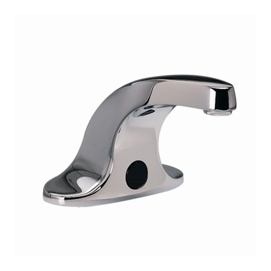
Innsbrook Lavatory Faucet
with SELECTRONIC™ Technology
Certified to comply with ASME A112.18.1M
© 2005 American Standard
M968498 Rev.1.2
NOTE TO INSTALLER: Please give this manual to the customer after installation.
To learn more about American Standard Faucets visit our website at: www.us.amstd.com or U.S.
customer's e-mail us at: faucetsupport@amstd.com
For Parts, Service, Warranty or other Assistance,
1-800-442-1902 (In Canada: 1-800-387-0369)
please call
Product No.'s & Options
Specifications
How to Install
Electrical Hook-up
Maintenance
FAQ,s
Replacement Parts
(In Toronto Area only: 1-905-3061093)
(In Toronto Area only: 1-905-3061093)
1
2
2-3
4-6
7-8
9
10
Advertisement
Table of Contents

Related Manuals for American Standard Innsbrook Lavatory Faucet M968498


Summary of Contents for American Standard Innsbrook Lavatory Faucet M968498
-
Page 1: Specifications
M968498 Rev.1.2 NOTE TO INSTALLER: Please give this manual to the customer after installation. To learn more about American Standard Faucets visit our website at: www.us.amstd.com or U.S. customer's e-mail us at: faucetsupport@amstd.com For Parts, Service, Warranty or other Assistance,... - Page 2 6056.202 6057.205 6057.202 605XTMV All American Standard Faucets Are Water Tested At Our Factory. Some Residual Water May Remain In The Faucet During Shipping. 5b. AC Power Supply (for 6056 series) 5c. 10 ft. Extension Wire (for 6057 series) 6. Circuit board 7.
-
Page 3: Installation
Fig. 1 155mm (6-1/8) 124mm (4-7/8) 38mm (1-1/2) MAX. 102mm 381mm (15) 81mm (3-3/16) 3/8" COMP. TOOLS REQUIRED; Fig. 2 1 Channel Locks 2 Adjustable Wrench 3 Plumbers' Putty or Caulking 4 Phillips Screwdriver 5 Flat Blade Screwdriver 6 Electric Drill & 1/4" Drill Bit 7 Tape Measure INSTALLATION INSTALL SPOUT ASSEMBLY;... - Page 4 MOUNT ENCLOSURE; Fig. 2 1. Determine location of ENCLOSURE (1). It must be located with-in the 14" (356mm) by 21" (533mm) shaded area shown in Figure 2 in order for electrical connections from the spout assembly to be made. NOTE: ENCLOSURE SUPPLY HOSE is 20". Distance between wall supply and ENCLOSURE (1) must be taken into consideration.
- Page 7 TWO PIECE GROMMET 4" TWO PIECE GROMMET BLACK...
-
Page 9: Solenoid Valve
Before opening ENCLOSURE CAUTION disconnect AC power supply. 1. Remove ENCLOSURE COVER. 2. Close SUPPLY STOP (5) with 4mm Hex wrench. Note: Keep water flowing out of faucet while shutting off. 3. Pull off Red (1) and Black (2) CONNECTORS from SOLENOID VALVE (3). - Page 10 FAQ'S Q: How will I know if battery needs to be replaced? A: Valve does not open and sensor blinks 2 times interrupted by pause for up to 7 days. Q: Why has the flow rate of the faucet reduced significantly? A: Check and clean aerator and strainer.
-
Page 11: Product Numbers
A923672-0070A M923115-0070A FAUCET SUPPLY PUTTY PLATE HOSE A913202-0070A WASHER A924162-0070A SUPPLY HOSE M962387-0070A MOUNTING SCREW KIT A922265-0070A 10 ft. MULTI EXTENSION WIRE (for 6057 series only) Replace the "YYY" with appropriate finish code CHROME HOT LINE FOR HELP For toll-free information and answers to your questions, call: 1 (800) 442-1902 Weekdays 8:00 a.m. - Page 12 M 9 6 8 4 9 8 R e v . 1 . 2...