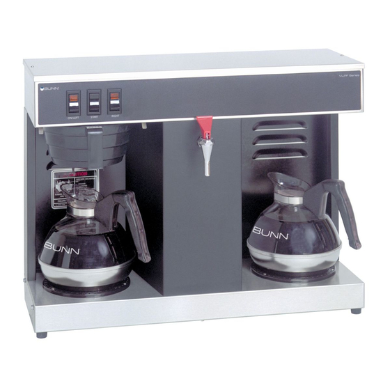
Bunn VLPF Operating & Service Manual
Hide thumbs
Also See for VLPF:
- Illustrated parts catalog (18 pages) ,
- Operating & service manual (28 pages)

Related Manuals for Bunn VLPF


Summary of Contents for Bunn VLPF
- Page 1 BUNN ® VLPF OPERATING & SERVICE MANUAL BUNN-O-MATIC CORPORATION OF CANADA 280 INDUSTRIAL PARKWAY SOUTH, AURORA, ONTARIO, L4G 3T9. PHONE: (905) 841-2866 FAX: (905) 841-2775 10179.7000H 02/07 ©1987 BUNN-O-MATIC CORPORATION...
- Page 2 BUNN’S SOLE OPTION AS SPECIFIED HEREIN, TO REPAIR, REPLACEMENT OR REFUND. In no event shall Bunn be liable for any other damage or loss, including, but not limited to, lost profits, lost sales, loss of use of equipment, claims of Buyer’s customers, cost of capital, cost of down time, cost of substitute equipment, facilities or services, or any other special, incidental, consequential or punitive damages.
- Page 3 FAILURE TO COMPLY RISKS EQUIPMENT DAMAGE, FIRE, OR SHOCK HAZARD READ THE ENTIRE OPERATING MANUAL BEFORE BUYING OR USING THIS PRODUCT THIS APPLIANCE IS HEATED WHENEVER CONNECTED TO A POWER SOURCE 00831.0000F 3/98 ©1998 BUNN-O-MATIC CORPORATION #12364.7000 Page 3 10179 091599...
- Page 4 25 feet from the 1/2” water supply line. A tight coil of copper tubing in the water line will facilitate moving the brewer to clean the countertop. Bunn-O-Matic does not recommend the use of a saddle valve to install the brewer.
- Page 5 INITIAL SET-UP CAUTION - The brewer must be unplugged throughout the Initial Set-up, except when specified in the instruc- tions. 1. Remove the top lid from the brewer. 2. Rotate the control thermostat knob fully counterclockwise to the “OFF” position and replace the top lid. 3.
- Page 6 SET/LOCK switch to the “LOCK” position. This will prevent any program- ming to be done until switch is once again placed in the “SET” position. COFFEE BREWING 1. Insert a BUNN filter into the funnel. ®...
- Page 7 TROUBLESHOOTING A troubleshooting guide is provided to suggest probable causes and remedies for the most likely problems encountered. If the problem remains after exhausting the troubleshooting steps, contact the Bunn-O-Matic Technical Services Department. • • •Inspection, testing, and repair of electrical equipment should be performed only by qualified service person- nel.
- Page 8 TROUBLESHOOTING (cont.) PROBLEM PROBABLE CAUSE REMEDY Equipment will not operate 1. No power or incorrect voltage (A) Plug in brewer. (B) Check wall outlet for 120V ac (C) Check circuit breaker/fuse. Brew cycle will not start 1. No water Check plumbing and shut-off valves.
- Page 9 TROUBLESHOOTING (cont.) PROBLEM PROBABLE CAUSE REMEDY Automatic refill will not operate 2. Liquid level control system Refer to Service - Liquid Level after drawing hot water.(cont.) Control system for testing proce- dures. See page 20. 3. Relay Refer to Service - Relay for testing procedures.
- Page 10 TROUBLESHOOTING (cont.) PROBLEM PROBABLE CAUSE REMEDY Decanter warmer is not hot 1. Warmer switches (A) The decanter warmer switch must be in the upper position for the warmer to operate. (B) Refer to Service - On/Left or Right switch for testing proce- dures.
- Page 11 2. Incorrect decanter size. Use only 64 oz. decanters. Weak beverage 1. Type of paper filters BUNN paper filters should be ® used for proper extraction. 2. Coffee A sufficient quantity of fine or drip grind coffee should be used for proper extraction.
- Page 12 TROUBLESHOOTING (cont.) PROBLEM PROBABLE CAUSE REMEDY Weak beverage (cont.) 4. Funnel loading The BUNN paper filter should be ® centered in the funnel and the bed of ground coffee leveled by gentle shaking. 5. Water temperature Empty a decanter and place it on the left warmer.
-
Page 13: Table Of Contents
SERVICE This section provides procedures for testing and replacing various major components used in this brewer should service become necessary. Refer to Troubleshooting for assistance in determining the cause of any problem. COMPONENT ACCESS WARNING - Unplug the brewer before the removal of any panel or the replacement of any component The On/Left switch, Start switch, Right switch, solenoid valve, brew timer, liquid level control compo-... -
Page 14: Brew Timer
SERVICE (cont.) BREW TIMER (early models) 6. Disconnect the in-line connectors on the black and white wires from the timer to the wiring har- ness. 7. With a voltmeter, check the voltage across the black and white wires when the On/Left switch is in the upper position and the Start switch is pressed to the lower position and released. - Page 15 SERVICE (cont.) BREW TIMER (cont.)(late models) 5. With a voltmeter, check the voltage across termi- nals TL1 and TL4 when the “ON/OFF” switch is in the “ON” position. Connect the brewer to the power source. The indication must be 0 volts. If voltage is as described, proceed to #6.
- Page 16 SERVICE (cont.) BREW TIMER (cont.)(late models) phon from the tank after turning the switch “OFF”. 1. Modifying brew volumes. To modify a brew vol- The brewer remembers this volume and will continue ume, first check that the SET/LOCK switch is in the to brew batches of this size until the volume setting “SET”...
-
Page 17: Control Thermostat
SERVICE (cont.) 6. Disconnect the brewer from the power source. CONTROL THERMOSTAT If voltage is present as described, reconnect the blue wire, the control thermostat is operating properly. If voltage is not present as described, replace the control thermostat. Removal and Replacement 1. -
Page 18: Decanter Warmers
SERVICE (cont.) DECANTER WARMERS P1956.40 FIG. 8 DECANTER WARMERS Page 18... -
Page 19: Limit Thermostat
SERVICE (cont.) If voltage is present as described, reconnect the blue LIMIT THERMOSTAT wire and proceed to #4. If voltage is not present as described, refer to the Wir- ing Diagram and check the brewer wiring harness. 4. Remove the black wire from the limit thermo- stat. -
Page 20: Liquid Level Control System
SERVICE (cont.) LIQUID LEVEL CONTROL SYSTEM from any metal surface of the brewer. 6. With a voltmeter, check the voltage across termi- nals 1 & 3 when the On/Left switch is in the upper position. Connect the brewer to the power source. The indication must be 120 volts ac after a delay of approximately 5 seconds. - Page 21 SERVICE (cont.) LIQUID LEVEL CONTROL SYSTEM (cont.) Removal and Replacement: 1. Remove all wires from the liquid level control board terminals. 2. Remove the two #8-32 slotted-head screws hold- ing the circuit board to the brewer hood. 3. Install the new circuit board to the hood, making sure that the two lock-washers are in place below the board and above the spacers.
-
Page 22: On/Left Warmer Switch
SERVICE (cont.) ON/LEFT SWITCH If continuity is not present as described, replace the switch. Removal and Replacement: 1. Remove all wires from the switch terminals. 2. Compress the clips inside the hood and gently push the switch through the opening. 3. -
Page 23: Relay
SERVICE (cont.) 7. Check for continuity across terminals 2 & 7 when the On/Left switch is in the upper position only RELAY until the Start switch is pressed to the lower position and released. Connect the brewer to the power source. Continuity must return across these terminals after the approximate setting of the brew timer. -
Page 24: Right Warmer Switch
SERVICE (cont.) RIGHT SWITCH If continuity is present as describe, reconnect the wires, the switch is operating properly. If continuity is not present as described, replace the switch. Removal and Replacement: 1. Remove all wires from the switch terminals. 2. Compress the clips inside the hood and gently push the switch through the opening. -
Page 25: Solenoid Valve
SERVICE (cont.) SOLENOID VALVE : 658 Page 25... -
Page 26: Start Switch
START SWITCH P2172.80 P1987 Page 26 10179 060100... -
Page 27: Tank Heater
SERVICE (cont.) : 658 Page 27... -
Page 28: Wiring Diagram
��������� ������ ������� ���� ����� ��� � � ��� ��� ��� ��� ��� ��� ����� � � � ���� � ��� ����������� ����� � ���� ������������ ����������� ������ ����� ����� ��������� ���� ����� ��� �������� ����� ����� � �� ���� ��������� Page 28 10179 121704...