Table of Contents
Advertisement
GA-P35-DS3R/
GA-P35-S3R
LGA775 socket motherboard for Intel
Intel
Pentium
®
®
User's Manual
Rev. 1002
12ME-P35DS3R-1002R
* The WEEE marking on the product indicates this product must not be disposed of with user's other household waste
and must be handed over to a designated collection point for the recycling of waste electrical and electronic equipment!!
* The WEEE marking applies only in European Union's member states.
processor family/Intel
Core
processor family/
®
TM
Celeron
processor family
®
®
Advertisement
Table of Contents

Related Manuals for Gigabyte GA-P35-DS3R


Summary of Contents for Gigabyte GA-P35-DS3R
- Page 1 GA-P35-DS3R/ GA-P35-S3R LGA775 socket motherboard for Intel Core processor family/ ® Intel Pentium processor family/Intel Celeron processor family ® ® ® ® User's Manual Rev. 1002 12ME-P35DS3R-1002R * The WEEE marking on the product indicates this product must not be disposed of with user's other household waste and must be handed over to a designated collection point for the recycling of waste electrical and electronic equipment!! * The WEEE marking applies only in European Union's member states.
-
Page 3: Identifying Your Motherboard Revision
Copyright © 2007 GIGA-BYTE TECHNOLOGY CO., LTD. All rights reserved. The trademarks mentioned in this manual are legally registered to their respective owners. logo is exclusively licensed to GIGABYTE UNITED INC. by GIGA-BYTE TECHNOLOGY CO., LTD. GIGABYTE UNITED INC. is designated by GIGA-BYTE TECHNOLOGY CO., LTD as the exclusive global distributor of GIGABYTE branded motherboards. -
Page 4: Table Of Contents
Table of Contents Optional Items ......................... 6 Box Contents ......................... 6 GA-P35-DS3R/S3R Motherboard Layout ..............7 Block Diagram ........................ 8 Chapter 1 Hardware Installation ..................9 Installation Precautions ..................9 Product Specifications ..................10 Installing the CPU and CPU Cooler .............. 13 1-3-1 Installing the CPU .................... - Page 5 Chapter 3 Drivers Installation ..................55 Installing Chipset Drivers ................55 Software Applications ..................56 Driver CD Information ..................56 Hardware Information ..................57 Contact Us ..................... 57 Chapter 4 Unique Features ..................59 Xpress Recovery2 ..................59 BIOS Update Utilities ..................64 4-2-1 Updating the BIOS with the Q-Flash Utility ............
-
Page 6: Optional Items
Intel LGA775 CPU Installation Guide ® One IDE cable and one floppy disk drive cable GA-P35-DS3R: Four SATA 3Gb/s cables GA-P35-S3R: Two SATA 3Gb/s cables GA-P35-DS3R: One SATA bracket I/O Shield The box contents above are for reference only and the actual items shall depend on product package you obtain. -
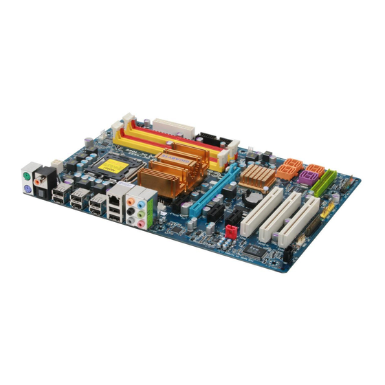
Page 7: Ga-P35-Ds3R/S3R Motherboard Layout
CLR_CMOS Intel ICH9R ® CODEC PCIE_2 BATTERY SATAII2 SATAII0 SPDIF_I PCI1 SATAII3 SATAII1 GSATAII0 GIGABYTE SATAII4 PCI2 SATA2 SATAII5 BIOS GSATAII1 IDE1 PCI3 F_PANEL F_USB4 F_USB3 F_USB2 F_USB1 PWR_LED "*" Only the GA-P35-DS3R adopts All-Solid Capacitor design. - 7 -... -
Page 8: Block Diagram
Block Diagram PCIe CLK CPU CLK+/- (100 MHz) LGA775 (333/266/200 MHz) Processor Host Interface DDR2 1066/800/667 MHz Dual Channel Memory PCI Express x16 Intel ® MCH CLK 2 SATA 3Gb/s (333/266/200 MHz) RJ45 ATA-133/100/66/33 IDE Channel GIGABYTE 8111B SATA2 BIOS PCI Express Bus 6 SATA 3Gb/s 3 PCI Express x1... -
Page 9: Chapter 1 Hardware Installation
Chapter 1 Hardware Installation Installation Precautions The motherboard contains numerous delicate electronic circuits and components which can become damaged as a result of electrostatic discharge (ESD). Prior to installation, carefully read the user's manual and follow these procedures: Prior to installation, do not remove or break motherboard S/N (Serial Number) sticker or •... -
Page 10: Product Specifications
Integrated in the South Bridge Up to 12 USB 2.0/1.1 ports (4 on the back panel, 8 via the USB brackets connected to the internal USB headers) "*" Only the GA-P35-DS3R adopts All-Solid Capacitor design. GA-P35-DS3R/S3R Motherboard - 10 -... - Page 11 Internal Connectors 1 x 24-pin ATX main power connector 1 x 4-pin ATX 12V power connector 1 x floppy disk drive connector 1 x IDE connector 8 x SATA 3Gb/s connectors 1 x CPU fan header 2 x system fan headers 1 x power fan header 1 x front panel header 1 x front panel audio header...
- Page 12 4 GB. (Note 2) Available functions in Easytune may differ by motherboard model. (Note 3) Due to chipset limitation, Intel ICH9R RAID driver does not support Windows 2000 operating system. GA-P35-DS3R/S3R Motherboard - 12 -...
-
Page 13: Installing The Cpu And Cpu Cooler
Installing the CPU and CPU Cooler Read the following guidelines before you begin to install the CPU: • Make sure that the motherboard supports the CPU. (Go to GIGABYTE's website for the latest CPU support list.) • Always turn off the computer and unplug the power cord from the power outlet before installing the CPU to prevent hardware damage. - Page 14 CPU notches with the socket alignment keys) and gently insert the CPU into position. Step 5: Once the CPU is properly inserted, replace the load plate and push the CPU socket lever back into its locked position. GA-P35-DS3R/S3R Motherboard - 14 -...
-
Page 15: Installing The Cpu Cooler
1-3-2 Installing the CPU Cooler Follow the steps below to correctly install the CPU cooler on the motherboard. (The following procedure uses Intel boxed cooler as the example cooler.) ® Male Push Pin Direction of the Arrow Sign on the Male The Top Push Pin of Female... -
Page 16: Installing The Memory
Flex Memory Mode will appear during the POST. Intel Flex Memory ® Technology offers greater flexibility to upgrade by allowing different memory sizes to be populated and remain in Dual Channel mode/performance. GA-P35-DS3R/S3R Motherboard - 16 -... -
Page 17: Installing A Memory
1-4-2 Installing a Memory Before installing a memory module , make sure to turn off the computer and unplug the power cord from the power outlet to prevent damage to the memory module. DDR2 DIMMs are not compatible to DDR DIMMs. Be sure to install DDR2 DIMMs on this motherboard. -
Page 18: Installing An Expansion Card
PCI Ex- press x16 slot. • Removing the Card: Press the white latch at the end of the PCI Express x16 slot to release the card and then pull the card straight up from the slot. GA-P35-DS3R/S3R Motherboard - 18 -... -
Page 19: Installing The Sata Bracket
SATA device. For SATA device in external enclosure, you only need to connect the SATA signal cable. Before connecting the SATA signal cable, make sure to turn off the power of the external enclosure. "*" The SATA bracket is included with the GA-P35-DS3R only. - 19 - Hardware Installation... -
Page 20: Back Panel Connectors
• When removing the cable, pull it straight out from the connector. Do not rock it side to side to prevent an electrical short inside the cable connector. GA-P35-DS3R/S3R Motherboard - 20 -... - Page 21 Center/Subwoofer Speaker Out Jack (Orange) Use this audio jack to connect center/subwoofer speakers in a 5.1/7.1-channel audio configuration. Rear Speaker Out Jack (Black) Use this audio jack to connect rear speakers in a 4/5.1/7.1-channel audio configuration. Side Speaker Out Jack (Gray) Use this audio jack to connect side speakers in a 7.1-channel audio configuration.
-
Page 22: Internal Connectors
• After installing the device and before turning on the computer, make sure the device cable has been securely attached to the connector on the motherboard. GA-P35-DS3R/S3R Motherboard - 22 -... - Page 23 1/2) ATX_12V_2X/ATX (2x2 12V Power Connector and 2x12 Main Power Connector) With the use of the power connector, the power supply can supply enough stable power to all the components on the motherboard. Before connecting the power connector, first make sure the power supply is turned off and all devices are properly installed.
- Page 24 This connector is used to connect a floppy disk drive. The types of floppy disk drives supported are: 360 KB, 720 KB, 1.2 MB, 1.44 MB, and 2.88 MB. Before connecting a floppy disk drive, locate the foolproof groove on the connector. GA-P35-DS3R/S3R Motherboard - 24 -...
- Page 25 8) IDE1 (IDE Connector) The IDE connector supports up to two IDE devices such as hard drives and optical drives. Before attaching the IDE cable, locate the foolproof groove on the connector. If you wish to connect two IDE devices, remember to set the jumpers and the cabling according to the role of the IDE devices (for example, master or slave).
- Page 26 The LED is on when the system is operating. The LED keeps blinking when the system is in S1 sleep state. The LED is off when the system is in S3/S4 sleep state or powered off (S5). Pin No. Definition MPD+ MPD- MPD- System Status LED Blinking S3/S4/S5 GA-P35-DS3R/S3R Motherboard - 26 -...
-
Page 27: Front Panel Header
12) F_PANEL (Front Panel Header) Connect the power switch, reset switch, speaker and system status indicator on the chassis front panel to this header according to the pin assignments below. Note the positive and negative pins before connecting the cables. Message/Power/ Power Speaker... -
Page 28: Cd In Connector
14) CD_IN (CD In Connector) You may connect the audio cable that came with your optical drive to the header. Pin No. Definition CD-L CD-R GA-P35-DS3R/S3R Motherboard - 28 -... - Page 29 15) SPDIF_I (S/PDIF In Header) This header supports digital S/PDIF in and can connect to an audio device that supports digital audio out via an optional S/PDIF in cable. For purchasing the optional S/PDIF in cable, please contact the local dealer. Pin No.
-
Page 30: Chassis Intrusion Header
Failure to do so may cause damage to the motherboard. • After system restart, go to BIOS Setup to load factory defaults (select Load Optimized Defaults) or manually configure the BIOS settings (refer to Chapter 2, "BIOS Setup," for BIOS configurations). GA-P35-DS3R/S3R Motherboard - 30 -... - Page 31 19) BATTERY The battery provides power to keep the values (such as BIOS configurations, date, and time information) in the CMOS when the computer is turned off. Replace the battery when the battery voltage drops to a low level, or the CMOS values may not be accurate or may be lost. You may clear the CMOS values by removing the battery: 1.
- Page 32 GA-P35-DS3R/S3R Motherboard - 32 -...
-
Page 33: Chapter 2 Bios Setup
Chapter 2 BIOS Setup BIOS (Basic Input and Output System) records hardware parameters of the system in the CMOS on the motherboard. Its major functions include conducting the Power-On Self-Test (POST) during system startup, saving system parameters and loading operating system, etc. BIOS includes a BIOS Setup program that allows the user to modify basic system configuration settings or to activate certain system features. -
Page 34: Startup Screen
BIOS Setup settings. You can access Boot Menu again to change the first boot device setting as needed. <End> Q-Flash Press the <End> key to access the Q-Flash utility directly without having to enter BIOS Setup first. GA-P35-DS3R/S3R Motherboard - 34 -... -
Page 35: The Main Menu
Once you enter the BIOS Setup program, the Main Menu (as shown below) appears on the screen. Use arrow keys to move among the items and press <Enter> to accept or enter a sub-menu. (Sample BIOS Version: GA-P35-DS3R F1b) CMOS Setup Utility-Copyright (C) 1984-2007 Award Software... - Page 36 (Pressing <F10> can also carry out this task.) Exit Without Saving Abandon all changes and the previous settings remain in effect. Pressing <Y> to the confirmation message will exit BIOS Setup. (Pressing <Esc> can also carry out this task.) GA-P35-DS3R/S3R Motherboard - 36 -...
-
Page 37: Standard Cmos Features
Standard CMOS Features CMOS Setup Utility-Copyright (C) 1984-2007 Award Software Standard CMOS Features Date (mm:dd:yy) Mon, Apr 2 2007 Item Help Time (hh:mm:ss) 22:31:24 Menu Level IDE Channel 0 Master [None] IDE Channel 0 Slave [None] IDE Channel 1 Master [None] IDE Channel 1 Slave [None]... - Page 38 Base Memory Also called conventional memory. Typically, 640 KB will be reserved for the MS-DOS operating system. Extended Memory The amount of extended memory. Total Memory The total amount of memory installed on the system. GA-P35-DS3R/S3R Motherboard - 38 -...
-
Page 39: Advanced Bios Features
Advanced BIOS Features CMOS Setup Utility-Copyright (C) 1984-2007 Award Software Advanced BIOS Features Hard Disk Boot Priority [Press Enter] Item Help First Boot Device [Floppy] Menu Level Second Boot Device [Hard Disk] Third Boot Device [CDROM] Password Check [Setup] HDD S.M.A.R.T. Capability [Disabled] CPU Hyper-Threading [Enabled]... - Page 40 Sets the PCI Express x16 graphics card as the first display. (Note) This item is present only if you install a CPU that supports this feature. For more information about Intel CPUs' unique features, please visit Intel's website. GA-P35-DS3R/S3R Motherboard - 40 -...
-
Page 41: Integrated Peripherals
Integrated Peripherals CMOS Setup Utility-Copyright (C) 1984-2007 Award Software Integrated Peripherals SATA RAID/AHCI Mode [Disabled] Item Help SATA Port0~3 Native Mode [Disabled] Menu Level USB Controller [Enabled] USB 2.0 Controller [Enabled] USB Keyboard Support [Disabled] USB Mouse Support [Disabled] Legacy USB storage detect [Enabled] Azalia Codec [Auto]... - Page 42 Note: The Gigabit hub will only operate at a speed of 10/100Mbps in MS-DOS mode; it will operate at a normal speed of 10/100/1000Mbps in Windows mode or when the LAN Boot ROM is activated. GA-P35-DS3R/S3R Motherboard - 42 -...
- Page 43 When a Cable Problem Occurs... If a cable problem occurs on a specified pair of wires, the Status field will show Short and thenlength shown will be the approximate distance to the fault or short. Example: Pair1-2 Status = Short / Length 1.6m Explanation: A fault or short might occur at about 1.6m on Pair 1-2.
-
Page 44: Power Management Setup
Power On by Ring Allows the system to be awakened from an ACPI sleep state by a wake-up signal from a modem that supports wake-up function. (Default: Enabled) (Note) Supported on Windows Vista operating system only. ® ® GA-P35-DS3R/S3R Motherboard - 44 -... - Page 45 Resume by Alarm Determines whether to power on the system at a desired time. (Default: Disabled) If enabled, set the date and time as following: Date (of Month) Alarm : Turn on the system at a specific time on each day or on a specific day in a month.
-
Page 46: Pnp/Pci Configurations
BIOS auto-assigns IRQ to the second PCI slot. (Default) 3,4,5,7,9,10,11,12,14,15 Assigns IRQ 3,4,5,7,9,10,11,12,14,15 to the second PCI slot. PCI3 IRQ Assignment Auto BIOS auto-assigns IRQ to the third PCI slot. (Default) 3,4,5,7,9,10,11,12,14,15 Assigns IRQ 3,4,5,7,9,10,11,12,14,15 to the third PCI slot. GA-P35-DS3R/S3R Motherboard - 46 -... -
Page 47: Pc Health Status
PC Health Status CMOS Setup Utility-Copyright (C) 1984-2007 Award Software PC Health Status Reset Case Open Status [Disabled] Item Help Case Opened Menu Level Vcore DDR18V +3.3V +12V Current System Temperature Current CPU Temperature Current CPU FAN Speed 3375 RPM Current SYSTEM FAN1 Speed Current SYSTEM FAN2 Speed Current POWER FAN Speed... - Page 48 (Note) Before setting this item to Intel(R) QST, make sure at least DDRII1 or DDRII2 socket in Channel 0 is populated. A small portion of system memory will be shared when Intel QST is enabled. ® GA-P35-DS3R/S3R Motherboard - 48 -...
-
Page 49: Mb Intelligent Tweaker(M.i.t.)
MB Intelligent Tweaker(M.I.T.) CMOS Setup Utility-Copyright (C) 1984-2007 Award Software MB Intelligent Tweaker(M.I.T.) Robust Graphics Booster [Auto] Item Help CPU Clock Ratio (Note) [16X] Menu Level CPU Host Clock Control [Disabled] x CPU Host Frequency (Mhz) PCI Express Frequency (Mhz) [Auto] C.I.A. - Page 50 Memory Timing Configuration 2. System Voltage Control Determines whether to manually set the system voltages. Auto lets BIOS automatically set the system voltages as required. Manual allows all voltage control items below to be configurable. (Default: Manual) GA-P35-DS3R/S3R Motherboard - 50 -...
- Page 51 DDR2 OverVoltage Control Allows you to to set memory voltage. Normal Supplies the memory voltage as required. (Default) +0.1V ~ +0.7V Increases memory voltage by 0.1V to 0.7V at 0.1V increment. Note: Increasing memory voltage may result in damage to the memory. PCI-E OverVoltage Control Allows you to to set PCIe voltage.
-
Page 52: Load Fail-Safe Defaults
Press <Enter> on this item and then press the <Y> key to load the optimal BIOS default settings. The BIOS defaults settings helps the system to operate in optimum state. Always load the Optimized defaults after updating the BIOS or after clearing the CMOS values. GA-P35-DS3R/S3R Motherboard - 52 -... -
Page 53: Set Supervisor/User Password
2-12 Set Supervisor/User Password CMOS Setup Utility-Copyright (C) 1984-2007 Award Software Standard CMOS Features Load Fail-Safe Defaults Advanced BIOS Features Load Optimized Defaults Integrated Peripherals Set Supervisor Password Power Management Setup Set User Password PnP/PCI Configurations Save & Exit Setup Enter Password: PC Health Status Exit Without Saving... -
Page 54: Save & Exit Setup
Press <Enter> on this item and press the <Y> key. This exits the BIOS Setup without saving the changes made in BIOS Setup to the CMOS. Press <N> or <Esc> to return to the BIOS Setup Main Menu. GA-P35-DS3R/S3R Motherboard - 54 -... -
Page 55: Chapter 3 Drivers Installation
Chapter 3 Drivers Installation • Before installing the drivers, first install the operating system. (The following instructions use Windows XP as the example operating system.) • After installing the operating system, insert the motherboard driver disk into your optional drive. The driver Autorun screen is automatically displayed which looks like that shown in the screen shot below. -
Page 56: Software Applications
This page displays all the tools and applications that GIGABYTE develops and some free software. You may press the Install button following an item to install it. Driver CD Information This page provides information about the drivers, applications and tools in this driver disk. GA-P35-DS3R/S3R Motherboard - 56 -... -
Page 57: Hardware Information
Hardware Information This page provides information about the hardware devices on this motherboard. Contact Us Check the contacts information of the GIGABYTE headquarter in Taiwan and the overseas branch offices on the last page of this manual. - 57 - Drivers Installation... - Page 58 GA-P35-DS3R/S3R Motherboard - 58 -...
-
Page 59: Chapter 4 Unique Features
Chapter 4 Unique Features Xpress Recovery2 Xpress Recovery2 is an utility that allows you to quickly compress and back up your system data and perform restoration of it. Supporting NTFS, FAT32, and FAT16 file systems, Xpress Recovery2 can back up data on PATA and SATA hard drives and restore it. Before You Begin: •... - Page 60 Recovery2 (10 GB or more is recommended; actual size requirements vary, depending on the amount of data) (Figure 2). Figure 2 Figure 1 3. Select a file system (for example, NTFS) and begin the installation of the operating system (Figure 3). Figure 3 GA-P35-DS3R/S3R Motherboard - 60 -...
- Page 61 4. After the operating system is installed, right-click the My Computer icon on your desktop and select Manage (Figure 4). Go to Computer Management to check disk allocation. Xpress Recovery2 will save the backup file to the unallocated space (black stripe along the top)(Figure 5). Please note that if there is no enough unallocated space, Xpress Recovery2 cannot save the backup file.
- Page 62 Xpress Recovery2 will begin the backup process (Figure 11). Figure 10 Figure 11 3. When finished, go to Disk Management to check disk allocation. Xpress Recovery2 will automatically create a new partition to store the backup image file. Figure 12 GA-P35-DS3R/S3R Motherboard - 62 -...
- Page 63 D. Using the Restore Function in Xpress Recovery2 Select RESTORE to restore the backup to your hard drive in case the system breaks down. The RESTORE option will not be present if no backup is created before (Figure 13, 14). Figure 13 Figure 14 E.
-
Page 64: Bios Update Utilities
Intel P35 BIOS for P35-DS3R F1b <DEL>: BIOS Setup/Q-Flash <F9>: XpressRecovery2 <F12>: Boot Menu <End>: Qflash 04/03/2007-P35-ICH9-6A79OG07C-00 Because BIOS flashing is potentially risky, please do it with caution. Inadequate BIOS flashing may result in system malfunction. GA-P35-DS3R/S3R Motherboard - 64 -... - Page 65 B. Updating the BIOS When updating the BIOS, choose the location where the BIOS file is saved. The follow procedure assumes that you save the BIOS file to a floppy disk. Step 1: 1. Insert the floppy disk containing the BIOS file into the floppy disk drive. In the main menu of Q- Flash, use the up or down arrow key to select Update BIOS from Drive and press <Enter>.
- Page 66 Time, Date, Hard Disk Type... Press <Y> to load BIOS defaults Step 6: Select Save & Exit Setup and then press <Y> to save settings to CMOS and exit BIOS Setup. The procedure is complete after the system restarts. GA-P35-DS3R/S3R Motherboard - 66 -...
-
Page 67: Updating The Bios With The @Bios Utility
4-2-2 Updating the BIOS with the @BIOS Utility A. Before You Begin: 1. If your system supports Intel Hyper-Threading technology, disable this function in BIOS Setup. ® 2. In Windows, close all applications and TSR (Terminate and Stay Resident) programs. This helps prevent unexpected failures when performing a BIOS update. - Page 68 BIOS file could result in an unbootable system. Step 4: As the system boots, press <Delete> to enter the BIOS Setup program. Select Load Optimized Defaults and press <Enter> to load BIOS defaults. GA-P35-DS3R/S3R Motherboard - 68 -...
-
Page 69: Easytune 5
EasyTune 5 EasyTune 5 , an easy-to-use and convenient system overclocking and management tool, lets you do overclock and overvoltage in Windows environment, eliminating the need to enter the BIOS Setup program. EasyTune 5 provides the following functions : overclocking/overvoltage, C.I.A./ (Note 1) M.I.B. -
Page 70: Windows Vista Readyboost
• The USB flash drive has to have above 256 MB of memory capacity. • The recommend amount of memory to use for ReadyBoost acceleration is one to three times the amount of RAM installed in your computer. GA-P35-DS3R/S3R Motherboard - 70 -... -
Page 71: Chapter 5 Appendix
Chapter 5 Appendix Configuring SATA Hard Drive(s) To configure SATA hard drive(s), follow the steps below: A. Install SATA hard drive(s) in your computer. B. Configure SATA controller mode in BIOS Setup. C . Configure a RAID array in RAID BIOS. (Note 1) D. - Page 72 The BIOS Setup menus described in this section may differ from the exact settings for your motherboard. The actual BIOS Setup menu options you will see shall depend on the motherboard you have and the BIOS version. GA-P35-DS3R/S3R Motherboard - 72 -...
- Page 73 C. Configuring a RAID array in RAID BIOS Enter the RAID BIOS setup utility to configure a RAID array. Skip this step and proceed to the installation of Windows operating system for a non-RAID configuration. Step 1: After the POST memory test begins and before the operating system boot begins, look for a message which says "Press <Ctrl-I>...
- Page 74 Select Disks Strip Size : 128KB Capacity : 223.6 GB Create Volume [ HELP ] The following are typical values: RAID0 - 128KB RAID10 - 64KB RAID5 - 64KB ]-Change [TAB]-Next [ESC]-Previous Menu [ENTER]-Select Figure 5 GA-P35-DS3R/S3R Motherboard - 74 -...
- Page 75 Step 5: Enter the array capacity and press <Enter>. Finally press <Enter> on the Create Volume item to begin creating the RAID array. When prompted to confirm whether to create this volume, press <Y> to confirm or <N> to cancel (Figure 6). Intel(R) Matrix Storage Manager option ROM v7.5.0.1014 ICH9R wRAID5 Copyright(C) 2003-07 Intel Corporation.
- Page 76 [ HELP ] Are you sure you want to delete "Volume0"? (Y/N) : Deleting a volume will reset the disks to non-RAID. WARNING: ALL DISK DATA WILL BE DELETED. ]-Select [ESC]-Previous Menu [DEL]-Delete Volume Figure 8 GA-P35-DS3R/S3R Motherboard - 76 -...
-
Page 77: Configuring Gigabyte Sata2 Sata Controller
5-1-2 Configuring GIGABYTE SATA2 SATA Controller A. Installing SATA hard drive(s) in your computer Attach one end of the SATA signal cable to the rear of the SATA hard drive and the other end to available SATA port on the motherboard. If there is more than one SATA controller on your motherboard, refer to "Chapter 1,"... - Page 78 After the POST memory test begins and before the operating system boot begins, look for a message which says "Press <Ctrl-G> to enter RAID Setup Utility" (Figure 2). Press <Ctrl> + <G> to enter the GIGABYTE SATA2 RAID BIOS utility. GIGABYTE Technology Corp. PCIE-to-SATAII/IDE RAID Controller BIOSv1.06.59 Copyright (C) 2006-2007 GIGABYTE Technology. http://www.gigabyte.com.tw...
- Page 79 In the main screen, press <Enter> on the Create RAID Disk Drive item. Then the Create New RAID screen appears (Figure 4). GIGABYTE Technology Corp. PCIE-to-SATAII/IDE RAID Controller BBIOSv1.06.59 [ Create New RAID ] [ Hard Disk Drive List ]...
- Page 80 4. Set Block Size (RAID 0 only): Under the Block item, use the up or down arrow key to select the stripe block size (Figure 6), ranging from 4 KB to 128 KB. Press <Enter>. GIGABYTE Technology Corp. PCIE-to-SATAII/IDE RAID Controller BIOSv1.06.59 [ Create New RAID ]...
- Page 81 When finished, the new RAID array will be displayed in the RAID Disk Drive List block (Figure 8). GIGABYTE Technology Corp. PCIE-to-SATAII/IDE RAID Controller BIOSv1.06.59 [ Main Menu ] [ Hard Disk Drive List ] Create RAID Disk Drive Model Name...
- Page 82 7. Save and Exit Setup: After configuring the RAID array, select the Save And Exit Setup item in the main screen to save your settings before exiting the RAID BIOS utility, then press <Y> (Figure 10). GIGABYTE Technology Corp. PCIE-to-SATAII/IDE RAID Controller BIOSv1.06.59 [ Main Menu ]...
-
Page 83: Making A Sata Raid/Ahci Driver Diskette
5-1-3 Making a SATA RAID/AHCI Driver Diskette (Required for AHCI and RAID Mode) To successfully install operating system onto SATA hard drive(s) that is/are configured to RAID/AHCI mode, you need to install the SATA controller driver during the OS installation. Without the driver, the hard drive may not be recognized during the Windows setup process. -
Page 84: Installing The Sata Raid/Ahci Driver And Operating System
* If you do not have any device support disks from a mass storage device manufacturer, or do not want to specify additional mass storage devices for use with Windows, press ENTER. S=Specify Additional Device ENTER=Continue F3=Exit Figure 2 GA-P35-DS3R/S3R Motherboard - 84 -... - Page 85 Step 3: For Intel ICH9R SATA controllers: When Setup correctly recognizes the Intel ICH9R SATA RAID/AHCI driver in the floppy disk, a controller menu similar to Figure 3 below will appear. Use the arrow keys to select one of the items displayed and press <Enter>.
- Page 86 * If you do not have any device support disks from a mass storage device manufacturer, or do not want to specify additional mass storage devices for use with Windows, press ENTER. S=Specify Additional Device ENTER=Continue F3=Exit Figure 6 GA-P35-DS3R/S3R Motherboard - 86 -...
- Page 87 Step 4: After the SATA RAID/AHCI driver installation is completed, you can proceed with the Windows XP installation. WindowsXP Professional Setup Welcome to Setup. This port of the Setup program prepares Microsoft(R) Windows (R) XP to run on your computer. To set up Windows XP now, press ENTER.
-
Page 88: Configuring Audio Input And Output
• 4 channel audio: Front speaker out and Rear speaker out. • 5.1 channel audio: Front speaker out, Rear speaker out, and Center/Subwoofer speaker out. • 7.1 channel audio: Front speaker out, Rear speaker out, Center/Subwoofer speaker out, and Side speaker out. GA-P35-DS3R/S3R Motherboard - 88 -... - Page 89 Step 2: Click the Audio I/O tab. In the speaker list on the left, select 2CH Speaker, 4CH Speaker, 6CH Speaker, or 8CH Speaker according to the type of speaker configuration you wish to set up. Step 3: Everytime you connect an audio device to an audio jack, the Connected device box appears.
-
Page 90: Installing The S/Pdif In Cable (Optional)
A. Installing the S/PDIF In Cable: Step 1: First, attach the connector at the end of the cable to the SPDIF_IN header on your motherboard. Step 2: Secure the metal bracket to the chassis back panel with a screw. GA-P35-DS3R/S3R Motherboard - 90 -... - Page 91 S/PDIF Out: The S/PDIF out jacks can transmit audio signals to an external decoder for decoding to get the best audio quality. B. Conneting a S/PDIF out Cable Connect a S/PDIF coaxial cable or a S/PDIF optical cable (either one) to an external decoder for transmitting the S/PDIF digital audio signals.
-
Page 92: Configuring Microphone Recording
Note: The microphone functions on the front panel and back panel cannot be used at the same time. Step 3: Locate the Volume icon in your system tray and click it to open the volume control panel GA-P35-DS3R/S3R Motherboard - 92 -... - Page 93 Step 4: To hear the sound being recorded during the record- ing process when using the microphone function on the front panel, do not select the Mute check box under Front Pink In or Front Green In in Master Volume. It is recommended that you set the volume at a middle level.
-
Page 94: Using The Sound Recorder
3. To play a sound file, click the Play button 4. To stop playing, click the Stop button 5. You may use the Fast Forward button move to the beginning of a file or the Fast Back- ward button to the end. GA-P35-DS3R/S3R Motherboard - 94 -... -
Page 95: Troubleshooting
Troubleshooting 5-3-1 Frequently Asked Questions To read more FAQs for your motherboard, please go to the Support\Motherboard\FAQ page on GIGABYTE's website. Q: In the BIOS Setup program, why are some BIOS options missing? A: Some advanced options are hidden in the BIOS Setup program. Press <Delete> to enter BIOS Setup during the POST. -
Page 96: Troubleshooting Procedure
Turn on the power to start the computer. Press <Delete> to enter BIOS Setup. Select "Load Fail-Safe Defaults" (or "Load Optimized Defaults"). Select "Save & Exit Setup" to save changes and exit BIOS Setup. (Continued...) GA-P35-DS3R/S3R Motherboard - 96 -... - Page 97 The power supply, When the computer is turned on, is the CPU cooler running? CPU or CPU socket might fail. The problem is verified and solved. The graphics card, expansion slot, or Check if there is display on your monitor. monitor might fail.
- Page 98 Shenyang Tech. Support: TEL: +86-24-83992901 http://rma.gigabyte-usa.com FAX: +86-24-83992909 Web address: http://www.gigabyte.com.mx India Japan GIGABYTE TECHNOLOGY (INDIA) LIMITED NIPPON GIGA-BYTE CORPORATION WEB address : http://www.giga-byte.co.in/ WEB address : http://www.gigabyte.co.jp Saudi Arabia Singapore WEB address : http://www.gigabyte.com.sa GIGA-BYTE SINGAPORE PTE. LTD. Australia WEB address : http://www.gigabyte.com.sg...
- Page 99 Office of GIGA-BYTE TECHNOLOGY Co., Ltd. in POLAND Sweden WEB address : http://www.gigabyte.pl WEB address : http://www.giga-byte.se Ukraine France WEB address : http://www.gigabyte.kiev.ua GIGABYTE TECHNOLOGY FRANCE Romania WEB address : http://www.gigabyte.fr Representative Office Of GIGA-BYTE Technology Co., Ltd. Italy in Romania WEB address : http://www.giga-byte.it WEB address : http://www.gigabyte.com.ro...
- Page 100 - 100 -...