Mitsubishi Electric MS24WN Service Manual
Hide thumbs
Also See for MS24WN:
- Operating instructions manual (32 pages) ,
- Operating instructions manual (33 pages) ,
- Installation manual (9 pages)
Table of Contents
Advertisement
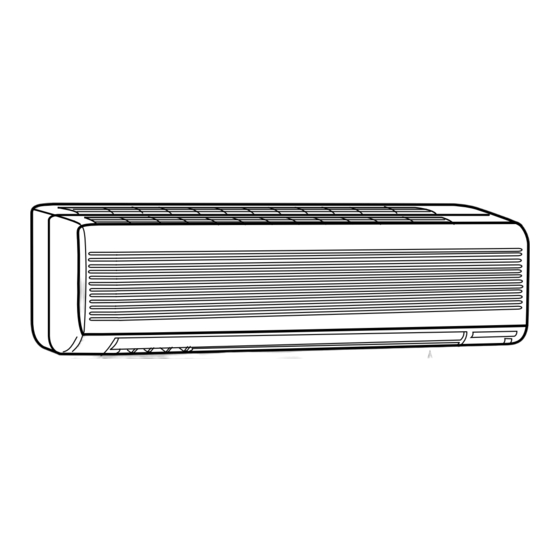
SPLIT-TYPE, AIR CONDITIONERS
SERVICE MANUAL
Wireless type
Models
MS24WN
INDOOR UNIT
Indication of model name
MS24WN
OUTDOOR UNIT
Indication of model name
MU24WN
· MU24WN
(W)
CONTENTS
1. FEATURES ·························································3
2. PART NAMES AND FUNCTIONS······················4
3. SPECIFICATION·················································6
4. DATA···································································8
5. OUTLINES AND DIMENSIONS ·······················12
6. WIRING DIAGRAM ··········································14
7. REFRIGERANT SYSTEM DIAGRAM ··············15
8. MICROPROCESSOR CONTROL ····················16
Remote
9. SERVICE FUNCTIONS ····································25
controller
10. TROUBLESHOOTING······································27
11. DISASSEMBLY INSTRUCTIONS·····················40
12. PARTS LIST······················································44
13. OPTIONAL PARTS ······················BACK COVER
C
Revision:
PARTS LIST have been partially modified.
Please void OB311.
The Slim Line.
From Mitsubishi Electric.
US
No. OB311
REVISED EDITION-A
TM
Advertisement
Table of Contents

Related Manuals for Mitsubishi Electric MS24WN


Summary of Contents for Mitsubishi Electric MS24WN
-
Page 1: Table Of Contents
7. REFRIGERANT SYSTEM DIAGRAM ··············15 MS24WN 8. MICROPROCESSOR CONTROL ····················16 Remote 9. SERVICE FUNCTIONS ····································25 controller 10. TROUBLESHOOTING······································27 11. DISASSEMBLY INSTRUCTIONS·····················40 12. PARTS LIST······················································44 13. OPTIONAL PARTS ······················BACK COVER OUTDOOR UNIT Indication of model name MU24WN The Slim Line. From Mitsubishi Electric. - Page 2 Revision: • Parts No. has been changed due to the color change of outdoor unit parts. WHITE NEW WHITE (Brighter) • Capillary tube has been added to parts list. Model Part name Part number Page CAPILLARY TUBE (TAPER PIPE) MU24WN E02 784 936 [0.14X[0.09X1-31/32...
-
Page 3: Features
It has a liquid crystal display which indicates such information as mode, fan speed and temperature selected as well as the programmed ON/OFF timer. It is also equipped with “I Feel Control”, a unique Mitsubishi Electric fea- ture that allows the user to adjust the temperature to exactly the level he or she wants simply by tapping the button that describes present conditions : “Too Cool”... -
Page 4: Part Names And Functions
PART NAMES AND FUNCTIONS INDOOR UNIT MS24WN Grille Air inlet Deodorizing filter (option) (Gray sponge type) Air cleaning filter (option) (White bellows type) Front panel Remote control receiving section Horizontal vane Air filter Remote controller Vertical vane Display section Operation section... -
Page 5: Remote Controller
REMOTE CONTROLLER MS24WN Signal transmitting section Operation display section OPERATE/ STOP (ON/ OFF)button ON/OFF WARM COOL TEMPERATURE buttons Open the front lid. CLOCK ON/OFF WARM COOL VANE button FAN SPEED CONTROL button (Horizontal vane button) STOP I FEEL COOL OFF-TIMER button... -
Page 6: Specification
SPECIFICATION Model MS24WN Item Cooling capacity Btu/h 22,800 Power consumption 2,170 [SEER] 10.5 (10.5) INDOOR UNIT MODEL MS24WN External finish White Power supply 115V 60Hz 1[ Max. fuse size (time delay)/ Disconnect switch Min. ampacity Fan motor F.L.A 0.82 431-491-565 Airflow Low—Med.—High... - Page 7 Outdoor unit Indoor unit Outside Outside Wall Wall diameter diameter thickness thickness Gas : 16-15/16 Gas : MS24WN MU24WN [ 5/8 0.0315 [ 3/8 0.0285 Liquid : 19-11/16 Liquid : MAX. HEIGHT DIFFERENCE Indoor unit Height difference should be within 25ft.
-
Page 8: Data
DATA 4-1. PERFORMANCE DATA 1) COOLING CAPACITY MS24WN MU24WN (208V/ 230V) Indoor air Outdoor intake air DB temperature ( ˚F ) Model ( ˚F ) 27.9 13.9 1.93 26.1 13.0 2.12 24.5 12.2 2.28 22.8 11.3 2.40 21.0 10.4 2.50 MS24WN 26.4... - Page 9 4-3. Condensing pressure Data is based on the condition of indoor humidity 50%. Air flow should be set at High. MU24WN (PSIG) (PSIG) 104( F) 104( F) Outdoor ambient temperature Outdoor ambient temperature...
-
Page 10: Standard Operation Data
4-4. STANDARD OPERATION DATA Model MS24WN Unit Cooling Item Btu / h Capacity 22,800 Total — 0.63 Input 2.17 INDOOR UNIT MODEL MS24WN Power supply 115V 60Hz 1[ Input 0.071 Fan motor current 0.62 Electrical OUTDOOR UNIT MODEL MU24WN circuit... - Page 11 Outdoor unit Refrigerant piping length (one way) precharged Model (up to 25ft.) 25ft. 30ft. 35ft. 40ft. 45ft. 50ft. 4 lb. 5 oz. 0.81 1.62 2.43 3.24 4.05 MS24WN MU24WN CALCULATION : Xoz. = 0.81/ 5oz./ft. x (Additional Piping Length-25) ft.
-
Page 12: Outlines And Dimensions
OUTLINES AND DIMENSIONS MS24WN Unit: inch INDOOR UNIT Installation plate Indoor unit 3-7/8 6-13/16 42-1/16 16-5/16 16-5/16 3-7/8 6-13/16 Wall hole [ 2-15/16 8-7/8 3/16 43-5/16 Installation plate Liquid line [ 3/8 19-11/16 Gas line [ 3/4 16-15/16 Insulation [ 1-15/16 O.D Air in [ 1-1/4 I.D... - Page 13 MU24WN Unit: inch OUTDOOR UNIT Outdoor Unit-Necessary surrounding clearance 7-9/32 19-11/16 7-9/32 Air intake Note:Allow adequate upper clearance 13/32 13/32 Air intake Front opening Air outlet Terminal block for power line 34-1/4 13/32 Terminal block for indoor and outdoor unit connection Service space 11-7/8 19-11/16...
-
Page 14: Wiring Diagram
WIRING DIAGRAM MS24WN MODEL WIRING DIAGRAM INDOOR UNIT RT13 CN201 HIC1 TO OUTDOOR RT12 UNIT CONNECTING CN112 WIRES NR11 12V DC FROM OUTDOOR UNIT TRANS CONNECTING WIRES SR141 TAB12 POWER SUPPLY CN211 115V 1 phase RT11 ELECTRONIC CONTROL P.C. BOARD... -
Page 15: Refrigerant System Diagram
REFRIGERANT SYSTEM DIAGRAM Unit: inch MS24WN MU24WN INDOOR UNIT OUTDOOR UNIT Refrigerant pipe [5/8 Strainer (with heat insulator) #100 Indoor coil Stop valve Indoor SERVICE thermistor (with service port) heat Outdoor Discharge PORT exchanger RT12(main) heat Flared connection SERVICE temperature... -
Page 16: Microprocessor Control
MICROPROCESSOR CONTROL MS24WN MU24WN WIRELESS REMOTE CONTROLLER Once the operation mode is set, the same operation mode Signal transmitting section can be repeated by simply turning the OPERATE/STOP(ON/OFF) button ON. Indoor unit receives the signal with a beep tone. Operation display section... - Page 17 (4) The initial set temperature is decided by the initial room temperature. Mode Initial room temperature Initial set temperature 79-F or more 75-F COOL mode of "I FEEL CONTROL" Initial room temperature 77-F to 79-F minus 4-F DRY mode of Initial room temperature more than 55-F, less than 77-F "I FEEL CONTROL"...
- Page 18 Operation chart Example Compressor Outdoor fan (continuously at set speed) Indoor fan 3. Discharge temperature protection The compressor is controlled by the temperature of discharge temperature thermistor RT62 for excess rise protection of compressor discharge pressure. • Compressor When the temperature of discharge temperature thermistor RT62 goes to 248°F or more, the compressor is turned OFF. After 3 minutes since the compressor has been turned OFF, if the temperature of discharge temperature thermistor RT62 becomes 212°F or less, the compressor is turned ON.
- Page 19 8-2. COOL ( ) OPERATION (1) Press OPERATE/STOP(ON/OFF) button. OPERATION INDICATOR lamp of the indoor unit turns on with a beep tone. (2) Select COOL mode with the OPERATION SELECT button. (3) Press TEMPERATURE buttons. (TOO WARM or TOO COOL button) to select the desired temperature. The setting range is 59 ~ 89°F.
- Page 20 8-6. AUTO VANE OPERATION 1. Horizontal vane (1) Vane motor drive This model is equipped with a stepping motor for the horizontal vane. The rotating direction, speed, and angle of the motor are controlled by pulse signals (approx. 12V) transmitted from microprocessor. (2) The horizontal vane angle and mode change as follows by pressing the VANE button.
- Page 21 • In the following example, the vertical vane is set to (front.). COOL / DRY Fan speed : Faster Solid arrow : When the LONG mode is used. Dotted arrow : When the LONG mode is not used. 2. Vertical vane (1) Vane motor drive This model is equipped with a stepping motor for the vertical vane.
- Page 22 (4) Press HR. and MIN. button (TIME set button) to set the timer. Time setting is 10-minute units. HR. and MIN. button will work when “ ” or “ ” mark is flashing. These marks disappear in 1 minute. After setting the ON timer, check that OPERATION INDICATOR lamp of the indoor unit lights. NOTE1 :Be sure to place the remote controller at the position where its signal can reach the air conditioner even during TIMER operation, or the set time may deviate within the range of about 10 minutes.
- Page 23 8-9. LEV control LEV (Expansion valve) is controlled by “Thermostat ON” commands given from the unit. Controlled range Minimum : 54 pulse, Maximum : 500 pulse 30 ~ 90 pulse / second Drive speed Opening set The setting is always in opening direction. (To close the LEV, it is closed to the pulse smaller than the one which is set finally.
- Page 24 2 When the temperature difference RT between indoor coil thermistor (main) RT12 and indoor coil thermistor (sub) RT13 in the indoor unit is 4deg. or more for a fixed time at cool or dry operation, the target discharge temperature is changed.
-
Page 25: Service Functions
SERVICE FUNCTIONS MS24WN 9-1. TIMER SHORT MODE For service, set time can be shortened by short circuit of JPG and JPS the electronic control P.C. board. The time will be shortened as follows. (Refer to page 37.) Set time : 1 minute... - Page 26 9-3. AUTO RESTART FUNCTION When the indoor unit is controlled with the remote controller, the operation mode, the set temperature, and the fan speed are memorized by the indoor electronic control P.C. board. When the main power is turned off and then turned back on, the unit restarts automatically in the memorized set conditions approximately after 3 minutes.
-
Page 27: Troubleshooting
TROUBLESHOOTING MS24WN MU24WN 10-1. Cautions on troubleshooting 1. Before troubleshooting, check the following: 1) Check the power supply voltage. 2) Check the indoor/outdoor connecting wire for mis-wiring. 2. Take care the following during servicing. 1) Before servicing the air conditioner, first be sure to turn off the remote controller to stop the unit, and then after con- firming the horizontal vane is closed, turn off the breaker and / or disconnect the power plug. - Page 28 10-2. Instruction of troubleshooting Start Indoor unit Indoor unit Indoor unit operates. OPERATION INDICATOR operates. doesn't receive Outdoor unit lamp on the indoor unit is Outdoor unit the signal from doesn't flashing on and off. doesn't operate remote controller. operate. normally.
- Page 29 1. Troubleshooting check table • The following indication applies regardless of shape of the indicator. flashing · Flashing of the OPERATION INDICATOR lamp (on the left-hand side) Operation Indicator indicates possible abnormalities. · The OPERATION INDICATOR lamp (on the left-hand side) is lighted during normal operation.
- Page 30 2. Trouble criterion of main parts MS24WN MU24WN Part name Check method and criterion Figure Room temperature Measure the resistance with a tester. (Part temperature 50˚F ~ 86˚F) thermistor(RT11) Normal Abnormal Indoor coil thermistor Open or short-circuit 8 k" ~ 20 k"...
-
Page 31: A Check Of Indoor Fan Motor
When OPERATION INDICATOR lamp flashes 3-time. Indoor fan motor doesn’t operate. Turn OFF the power supply. Check connector CN211 visually. Check of indoor fan motor Is soldering point of the connector Resolder it. Are lead wires connected? correctly soldered? Reconnect the lead wires. Disconnect lead wires from connector CN211 on the indoor electronic control P.C. -
Page 32: Check Of Indoor Electronic Control P.c. Board
The unit doesn’t operate with the remote controller. Also, the OPERATION INDICATOR lamp doesn’t light up by pressing the EMERGENCY OPERATION switch. Check of indoor electronic control P.C. board Check the both “parts side”and “pattern side” of Varistor (NR11) indoor electronic control P.C. board visually. Turn OFF the power supply. -
Page 33: Check Of Outdoor Unit
Compressor and / or outdoor fan doesn’t operate. Check of outdoor unit Turn ON the power supply. Is there 208/230V AC Check the outdoor power supply between on the L1 - L2 and connection of wiring. outdoor terminal block Compressor does not operate. - Page 34 Compressor and / or outdoor fan motor doesn’t stop. Check of outdoor unit 1 Turn OFF the power supply. 2 After 30 seconds, turn ON the power supply again. 3 Operate the unit in COOL mode by pressing the EMERGENCY OPERATION switch. 4 Operate the unit for 1 minute or more and stop it by pressing the EMERGENCY OPERATION switch again.
- Page 35 When OPERATION INDICATOR lamp flashes ON and OFF in every 0.5-second. Outdoor unit doesn’t operate. F F How to check mis-wiring Start Turn OFF the power supply. Turn ON the power supply. Is the power voltage to terminal blocks of Rectify the wiring.
-
Page 36: Check Of Lev (Expansion Valve)
When OPERATION INDICATOR lamp flashes 10-time. Cooling doesn’t operate. Check of LEV (Expansion valve) 1 During pressing the OPERATION SELECT button and the TOO COOL button on the remote controller, press the RESET button. 2 First, release the RESET button. 1 During pressing the OPERATION SELECT (After 3 seconds, confirm all displays of the remote controller.) - Page 37 TEST POINT DIAGRAM AND VOLTAGE MS24WN Indoor electronic control P.C. board Varistor(NR11) Fan motor power supply Power supply input 115V AC 5V DC Fuse (F11) 250V AC 3.15A Room temperature thermistor(RT11) Indoor coil thermistor(RT12(main)) Indoor coil thermistor(RT13(sub)) R132 Emergency operation...
- Page 38 MU24WN Outdoor electronic control P.C. board Ambient temperature thermistor (RT63) Discharge temperature thermistor(RT62) -4 14 32 50 68 86 104 32 50 68 86 104 122 140 158 176 194 212 230 248 Temperature(-F) Temperature(-F) CN662 3-4 CN662 1-2 Ambient Discharge Fan motor temperature...
- Page 39 RELAY OPERATION MS24WN COMPRESSOR CONTACTOR • EACH MODE MODE THERMOSTAT 52C CONTACTOR INDOOR FAN SPEED COOL & COOL mode AUTO or set speed of I FEEL CONTROL OFF for 2 min. AUTO or set speed after unit starts operation Repeat of 8 min. ON/ 3min.
-
Page 40: Disassembly Instructions
2Pull the terminal while pull out the terminal pushing the locking slowly. Locking lever lever. Connector 11-1. MS24WN INDOOR UNIT OPERATING PROCEDURE PHOTOS 1. Removing the front panel Photo 1 (1) Remove the screw caps of the front panel. Front panel Remove the screws. - Page 41 OPERATING PROCEDURE PHOTOS 3. Removing the electrical box Photo 3 Screws of the ground wire (1) Remove the front panel. (Refer to 1.) (2) Remove the electrical cover. (Refer to 2.) (3) Disconnect the connector of the indoor coil Fan motor thermistor (CN112), the fan motor connector (CN211 and connectors CN121) and the vane motor connector (CN151) on the...
- Page 42 11-2. MU24WN OUTDOOR UNIT OPERATING PROCEDURE PHOTOS Photo 1 1. Removing the cabinet (1) Remove the screws of the top panel and the top panel. (2) Remove the screw of the service panel. To remove the service panel, pull it down toward you and unhook the Screws of the top panel catches on the both sides.
- Page 43 OPERATING PROCEDURE PHOTOS Photo 5 4. Removing the heat exchanger and compressor (1) Remove the screws of the rear panel. Remove the Screws of the screws of the valve bed and the valve bed. rear guard (The valve bed is fixed by the catches on the right and left sides.
-
Page 44: Parts List
PARTS LIST MS24WN (W) 12-1. INDOOR UNIT STRUCTURAL PARTS 12-2. INDOOR UNIT HEAT EXCHANGER Optional CATCH parts (See SCREW back cover.) 12-1. INDOOR UNIT STRUCTURAL PARTS Part number that is circled is not shown in the illustration. Q'ty/unit Symbol Part No. -
Page 45: Electrical Parts
MS24WN (W) 12-4. ACCESSORY AND 12-3. INDOOR UNIT FUNCTIONAL PARTS AND REMOTE CONTROLLER ELECTRICAL PARTS SLEEVE BEARING ROOM TEMPERATURE THERMISTOR 15 16 VARISTOR FUSE 12-3. INDOOR UNIT FUNCTIONAL PARTS AND ELECTRICAL PARTS Part numbers that are circled are not shown in the illustration. - Page 46 MU24WN 12-5. OUTDOOR UNIT STRUCTURAL PARTS, ELECTRICAL PARTS AND FUNCTIONAL PARTS...
- Page 47 MU24WN 12-5. OUTDOOR UNIT STRUCTURAL PARTS, ELECTRICAL PARTS AND FUNCTIONAL PARTS Part numbers that are circled are not shown in the illustration. Q'ty/unit Symbol Part No. Part Name in Wiring Remarks MU24WN Diagram E02 813 297 NEW WHITE(Brighter) TOP PANEL E02 528 309 RT62, RT63 THERMISTOR...
-
Page 48: Optional Parts
DEODORIZING FILTER and AIR CLEANING FILTER can be attached on either side. Deodorizing filter (Gray sponge type) C C Copyright 2003 MITSUBISHI ELECTRIC ENGINEERING CO.,LTD. Distributed in Jan. 2004. No. OB311 REVISED EDITION-A 6 New publication, effective Jan. 2004 Distributed in Mar. 2003. No. OB311 17... - Page 49 3400 Lawrenceville Suwanee Road Suwanee, Georgia 30024 ● Toll Free: 800-433-4822 Toll Free Fax: 800-889-9904 ● www.mrslim.com Specifications are subject to change without notice.