Table of Contents
Advertisement
www.proform.com
Model No. PFTL70011.0
USER'S MANUAL
Serial No.
Write the serial number in the space
above for reference.
Serial Number
Decal
QUESTIONS?
If you have questions, or if parts
are damaged or missing, DO NOT
CONTACT THE STORE; please
contact Customer Care.
IMPORTANT: Please register this
product (see the limited warranty
on the back cover of this manual)
before contacting Customer Care.
CALL TOLL-FREE:
1-888-533-1333
Mon.–Fri. 6 a.m.–6 p.m. MT
Sat. 8 a.m.–4 p.m. MT
ON THE WEB:
www.proformservice.com
CAUTION
Read all precautions and instruc-
tions in this manual before using
this equipment. Keep this manual
for future reference.
Advertisement
Table of Contents

Related Manuals for ProForm Cardio Smart DMD-2050E


Summary of Contents for ProForm Cardio Smart DMD-2050E
- Page 1 Model No. PFTL70011.0 USER’S MANUAL Serial No. Write the serial number in the space above for reference. Serial Number Decal QUESTIONS? If you have questions, or if parts are damaged or missing, DO NOT CONTACT THE STORE; please contact Customer Care.
-
Page 2: Table Of Contents
Apply the decal in the location shown. Note: The decals may not be shown at actual size. PROFORM is a registered trademark of ICON IP, Inc. -
Page 3: Important Precautions
14. To informed of all warnings and precautions. purchase a surge suppressor, see your local PROFORM dealer, call the telephone number 3. Use the treadmill only as described. on the front cover of this manual, or see your local electronics store. - Page 4 DANGER: 20. Never leave the treadmill unattended while Always unplug the power it is running. Always remove the key, unplug cord immediately after use, before clean- the power cord, and press the power switch ing the treadmill, and before performing the into the off position when the treadmill is not maintenance and adjustment procedures in use.
-
Page 5: Before You Begin
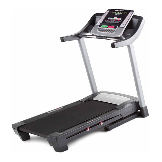
BEFORE YOU BEGIN Thank you for selecting the new PROFORM CARDIO reading this manual, please see the front cover of this ® SMART treadmill. The CARDIO SMART treadmill manual. To help us assist you, note the product model provides an impressive selection of features designed number and serial number before contacting us. -
Page 6: Part Identification Chart
PART IDENTIFICATION CHART Use the drawings below to identify small parts used for assembly. The number in parentheses below each draw- ing is the key number of the part, from the PART LIST near the end of this manual. The number following the key number is the quantity used for assembly. -
Page 7: Assembly
ASSEMBLY • Assembly requires two persons. • Assembly requires the following tools: the included hex keys • Place all parts in a cleared area and remove the packing materials. Do not dispose of the packing one adjustable wrench materials until you finish all assembly steps. one Phillips screwdriver • The underside of the walking belt is coated with high-performance lubricant. - Page 8 2. Identify the Left Upright (75), which is marked "Left." Have a second person hold the Left Upright near the Base (80). Wire See the inset drawing. Tie the wire tie in the Left Upright (75) securely around the end of the Upright Wire (70).
- Page 9 4. Identify the Left and Right Base Covers (73, 74), which are marked either “Left” and “Right” or “L” and “R.” Slide the Left and Right Base Covers onto the Left and Right Uprights (75, 76) as shown. Remove the tie from the Upright Wire (70). Wire 5.
- Page 10 6. Set the Console Base (83) face down on a soft surface to avoid scratching the Console Base. Remove the two screws (A) from the Pulse Crossbar (31). Remove the Pulse Crossbar and discard the screws. Remove the four 5/16" x 5/8" Screws (7) from the Console Frame (87).
- Page 11 8. IMPORTANT: To avoid damaging the Pulse Crossbar (31), do not use power tools and do not overtighten the #10 x 3/4" Screws (13). Orient the Pulse Crossbar (31) as shown. Attach the Pulse Crossbar to the Left and Right Handrails (71, 72) with four #10 x 3/4"...
- Page 12 10. Set the console assembly on the Left and Right Console Handrails (71, 72). Make sure that no wires Assembly are pinched. Insert the excess Upright Wire (70) behind the Console Frame (87). Attach the console assembly to the brackets on the Handrails (71, 72) with the four 5/16"...
- Page 13 13. Raise the Frame (49) to the position shown. Have a second person hold the Frame until this step is completed. Orient the Storage Latch (51) so that the large barrel and the latch knob are oriented as shown. Attach the lower end of the Storage Latch (51) to the Base (80) with a 3/8"...
-
Page 14: Operation And Adjustment
OPERATION AND ADJUSTMENT HOW TO CONNECT THE POWER CORD nominal 120-volt circuit capable of carrying 15 or more amps. To avoid overloading the circuit, do Use a Surge Suppressor not plug other electrical devices, except for low- power devices such as cell phone chargers, into Your treadmill, like other electronic equipment, can be the surge suppressor or into an outlet on the same circuit. - Page 15 CONSOLE DIAGRAM FEATURES OF THE CONSOLE You can even listen to your favorite workout music or audio books with the console’s stereo sound system The treadmill console offers an impressive array of while you exercise. features designed to make your workouts more effec- To turn on the power, see page 16.
-
Page 16: Turn On Power
HOW TO TURN ON THE POWER HOW TO USE THE MANUAL MODE IMPORTANT: If the treadmill has been exposed to 1. Insert the key into the console. cold temperatures, allow it to warm to room tem- perature before you turn on the power. If you do See HOW TO TURN ON THE POWER at the left. - Page 17 5. Follow your progress with the displays. To measure your heart The matrix—When rate, stand on the foot rails you select the manual mode, the matrix will and hold the display a track that rep- pulse bar with resents 1/4 mile (400 your palms on m).
- Page 18 HOW TO USE AN ONBOARD WORKOUT The workout will continue in this way until the last segment of the profile flashes in the display and the 1. Insert the key into the console. last segment ends. The walking belt will then slow to a stop.
- Page 19 HOW TO USE THE WEIGHT LOSS CENTER 4. Follow your progress with the displays. 1. Insert the key into the console. See step 5 on page 17. Note: The calorie goal is an estimate of the See HOW TO TURN ON THE POWER on page 16. number of calories that you will burn during 2.
- Page 20 HOW TO USE AN IFIT WORKOUT the button, the treadmill will automatically adjust to the first speed and incline settings of the workout. To purchase iFit cards at any time, go to www.iFit.com Hold the handrails and begin walking. or call the telephone number on the front cover of this manual.
- Page 21 THE INFORMATION MODE An “E” for English miles or an “M” for metric kilome- The console features an information mode that keeps ters will appear in the right track of the total distance that the walking belt has display. Press the Speed moved and the total number of hours that the treadmill increase button to change has been used.
-
Page 22: How To Fold And Move The Treadmill
HOW TO FOLD AND MOVE THE TREADMILL HOW TO FOLD THE TREADMILL HOW TO MOVE THE TREADMILL To avoid damaging the treadmill, adjust the incline Before moving the treadmill, fold it as described at the to the lowest position before you fold the treadmill. left. -
Page 23: Troubleshooting
TROUBLESHOOTING Most treadmill problems can be solved by follow- c. Remove the key from the console, and then ing the simple steps below. Find the symptom that reinsert it. applies, and follow the steps listed. If further assis- tance is needed, see the front cover of this manual. d. - Page 24 Lower the treadmill. Next, remove the three begin calibrating, press the Stop button again, and indicated #8 x 3/4" Screws (6). Carefully slide the then press the Incline increase or decrease button Motor Hood (57) off. again. When the incline is calibrated, remove the key from the console.
- Page 25 SYMPTOM: The walking belt is off-center or slips b. If the walking belt slips when walked on, first when walked on remove the key and UNPLUG THE POWER CORD. Using the hex key, turn both idler roller a. If the walking belt is off-center, first remove the screws clockwise, 1/4 of a turn.
-
Page 26: Exercise Guidelines
EXERCISE GUIDELINES Burning Fat—To burn fat effectively, you must exer- WARNING: cise at a low intensity level for a sustained period of Before beginning this time. During the first few minutes of exercise, your or any exercise program, consult your physi- body uses carbohydrate calories for energy. -
Page 27: Part List
PART LIST Model No. PFTL70011.0 R0312A Key No. Qty. Description Key No. Qty. Description #8 x 1/2" Ground Screw Frame 3/8" x 2 1/2" Bolt Right Foot Rail 3/8" Nut Storage Latch 3/8" x 4" Screw Right Rear Foot 3/8" Star Washer Left Rear Foot #8 x 3/4"... -
Page 28: Exploded Drawing
EXPLODED DRAWING A Model No. PFTL70011.0 R0312A... - Page 29 EXPLODED DRAWING B Model No. PFTL70011.0 R0312A...
- Page 30 EXPLODED DRAWING C Model No. PFTL70011.0 R0312A...
- Page 31 EXPLODED DRAWING D Model No. PFTL70011.0 R0312A...
-
Page 32: Ordering Replacement Parts
ORDERING REPLACEMENT PARTS To order replacement parts, please see the front cover of this manual. To help us assist you, be prepared to provide the following information when contacting us: • the model number and serial number of the product (see the front cover of this manual) • the name of the product (see the front cover of this manual) • t he key number and description of the replacement part(s) (see the PART LIST and the EXPLODED DRAWING near the end of this manual) LIMITED WARRANTY IMPORTANT: You must register this product within 30 days of the purchase date to avoid added fees for service needed under warranty.