Table of Contents
Advertisement
Quick Links
Advertisement
Table of Contents

Related Manuals for Supero SUPERO SUPERSERVER 5015B-MT


Summary of Contents for Supero SUPERO SUPERSERVER 5015B-MT
- Page 1 ® UPER 5015B-MT UPER ERVER USER’S MANUAL Revision 1.0a...
- Page 2 Please Note: For the most up-to-date version of this manual, please see our web site at www.supermicro.com. Super Micro Computer, Inc. ("Supermicro") reserves the right to make changes to the product described in this manual at any time and without notice. This product, including software, if any, and documentation may not, in whole or in part, be copied, photocopied, reproduced, translated or reduced to any medium or machine without prior written consent.
-
Page 3: About This Manual
Preface Preface About This Manual This manual is written for professional system integrators and PC technicians. It pro- vides information for the installation and use of the SuperServer 5015B-MT. Instal- lation and maintainance should be performed by experienced technicians only. The SuperServer 5015B-MT is a high-end single processor 1U rackmount server based on the SC813MTQ-300C server chassis and the X7SBi motherboard. - Page 4 UPER ERVER 5015B-MT User's Manual Chapter 4: System Safety You should thoroughly familiarize yourself with this chapter for a general overview of safety precautions that should be followed when installing and servicing the SuperServer 5015B-MT. Chapter 5: Advanced Motherboard Setup Chapter 5 provides detailed information on the X7SBi motherboard, including the locations and functions of connectors, headers and jumpers.
- Page 5 Preface Notes...
-
Page 6: Table Of Contents
Onboard Controllers/Ports ................1-2 Server Chassis Features ................1-4 System Power ....................1-4 Control Panel ....................1-4 Rear I/O Panel ....................1-4 Contacting Supermicro ..................1-5 Chapter 2 Server Installation Overview ......................2-1 Unpacking the System ..................2-1 Preparing for Setup ..................2-1 Choosing a Setup Location ................ - Page 7 Table of Contents Chapter 3 System Interface Overview ......................3-1 Control Panel Buttons ..................3-1 Reset ....................... 3-1 Power ......................3-1 Control Panel LEDs ..................3-2 Overheat/Fan Fail ................... 3-2 NIC2 ........................ 3-2 NIC1 ........................ 3-2 HDD ......................... 3-2 Power ......................3-3 SATA Drive Carrier LEDs ................
- Page 8 UPER ERVER 5015B-MT User's Manual Supero Doctor III ................... 5-23 Chapter 6 Advanced Chassis Setup Static-Sensitive Devices .................. 6-1 Precautions ..................... 6-1 Unpacking ....................... 6-1 Control Panel ....................6-2 System Fans ....................6-3 Drive Bay Installation/Removal ............... 6-3 Removing the Front Bezel ................6-3 Serial ATA Drive Installation ................
-
Page 9: Chapter 1 Introduction
Chapter 1 Introduction Overview The Supermicro SuperServer 5015B-MT is a high-end single processor, 1U rack- mount server with state-of-the-art features. The 5015B-MT is comprised of two main subsystems: the SC813MTQ-300C 1U chassis and the X7SBi motherboard. Please refer to our web site for information on operating systems that have been certifi ed for use with the 5015B-MT. -
Page 10: Motherboard Features
UPER ERVER 5015B-MT User's Manual Motherboard Features At the heart of the SuperServer 5015B-MT lies the X7SBi, a single processor motherboard based upon Intel's E3210 chipset. Below are the main features of the X7SBi. Processor The X7SBi supports single Intel Xeon 3200/3000 Series LGA775 processors at system bus speeds of 1333, 1066 and 800 MHz. -
Page 11: System Block Diagram
Chapter 1: Introduction Figure 1-1 . Intel 3210 Chipset: System Block Diagram Note: This is a general block diagram. Please see Chapter 5 for details. LGA775_PROCESSOR VRM 11 CK505 CLK FSB: 1333/1066/800 PCIE_x 8 1x PCIX_64 PCIE_x 8 DIMM_CHA DDR2_667/800 PCI- X B US DIMM_CHB Intel 3210... -
Page 12: Server Chassis Features
UPER ERVER 5015B-MT User's Manual Server Chassis Features The following is a general outline of the main features of the SC813MTQ-300C chassis. System Power When confi gured as a SuperServer 5015B-MT, the SC813MTQ-300C chassis in- cludes a single 300W power supply. Serial ATA Subsystem For the 5015B-MT, the SC813MT-300 chassis was designed to support four Serial ATA hard drives, which are hot-swappable units. -
Page 13: Contacting Supermicro
Super Micro Computer, Inc. 980 Rock Ave. San Jose, CA 95131 U.S.A. Tel: +1 (408) 503-8000 Fax: +1 (408) 503-8008 Email: marketing@supermicro.com (General Information) support@supermicro.com (Technical Support) Web Site: www.supermicro.com Europe Address: Super Micro Computer B.V. Het Sterrenbeeld 28, 5215 ML... - Page 14 UPER ERVER 5015B-MT User's Manual Notes...
-
Page 15: Chapter 2 Server Installation
Chapter 2: Server Installation Chapter 2 Server Installation Overview This chapter provides a quick setup checklist to get your SuperServer 5015B-MT up and running. Following the steps in the order given should enable you to have the system operational within a minimal amount of time. This quick setup assumes that your 5015B-MT system has come to you with the processor and memory prein- stalled. -
Page 16: Rack Precautions
UPER ERVER 5015B-MT User's Manual installation only in a Restricted Access Location (dedicated equipment rooms, service closets and the like). • This product is not suitable for use with visual display work place devices acccording to §2 of the the German Ordinance for Work with Visual Display Units. -
Page 17: Rack Mounting Considerations
Chapter 2: Server Installation Rack Mounting Considerations Ambient Operating Temperature If installed in a closed or multi-unit rack assembly, the ambient operating tempera- ture of the rack environment may be greater than the ambient temperature of the room. Therefore, consideration should be given to installing the equipment in an environment compatible with the manufacturer’s maximum rated ambient tempera- ture (Tmra). -
Page 18: Installing The System Into A Rack
UPER ERVER 5015B-MT User's Manual Installing the System into a Rack This section provides information on installing the SuperServer 5015B-MT into a rack unit with the rack rails provided. If the server has already been mounted into a rack, you can skip ahead to Sections 2-5 and 2-6. There are a variety of rack units on the market, which may mean the assembly procedure will differ slightly. -
Page 19: Installing The Rack Rails
Chapter 2: Server Installation Figure 2-1. Installing Rear Inner Chassis Rails Installing the Rack Rails Determine where you want to place the SuperServer 5015B-MT in the rack (see Rack and Server Precautions in Section 2-3). Position the chassis rail guides at the desired location in the rack, keeping the sliding rail guide facing the inside of the rack. -
Page 20: Installing The Server Into The Rack
UPER ERVER 5015B-MT User's Manual Installing the Server into the Rack You should now have rails attached to both the chassis and the rack unit. The next step is to install the server into the rack. Do this by lining up the rear of the chassis rails with the front of the rack rails. -
Page 21: Installing The Server Into A Telco Rack
Chapter 2: Server Installation Installing the Server into a Telco Rack To install the SuperServer 5015B-MT into a Telco type rack, use two L-shaped brackets on either side of the chassis (four total). First, determine how far the server will extend out the front of the rack. Larger chassis should be positioned to balance the weight between front and back. -
Page 22: Checking The Motherboard Setup
UPER ERVER 5015B-MT User's Manual Checking the Motherboard Setup After you install the 5015B-MT in the rack, you will need to open the unit to make sure the motherboard is properly installed and all the connections have been made. Accessing the Inside of the System Grasp the two handles on either side and pull the unit straight out until it locks (you will hear a "click"). -
Page 23: Checking The Drive Bay Setup
Chapter 2: Server Installation Figure 2-4. Accessing the Inside of the SuperServer 5015B-MT Checking the Drive Bay Setup Next, you should check to make sure the peripheral drives and the SATA drives and SATA backplane have been properly installed and all essential connections have been made. - Page 24 UPER ERVER 5015B-MT User's Manual Also note that all power and data cables have been routed in such a way that they do not block the airfl ow generated by the fans. Providing Power Plug the power cord from the power supply unit into a high-quality power strip that offers protection from electrical noise and power surges.
-
Page 25: Chapter 3 System Interface
Chapter 3: System Interface Chapter 3 System Interface Overview There are several LEDs on the control panel as well as others on the SATA drive carriers to keep you constantly informed of the overall status of the system as well as the activity and health of specifi... -
Page 26: Control Panel Leds
UPER ERVER 5015B-MT User's Manual Control Panel LEDs The control panel located on the front of the SC813MTQ-300C chassis has fi ve LEDs. These LEDs provide you with critical information related to different parts of the system. This section explains what each LED indicates when illuminated and any corrective action you may need to take. -
Page 27: Power
Chapter 3: System Interface Power Indicates power is being supplied to the system's power supply units. This LED should normally be illuminated when the system is operating. SATA Drive Carrier LEDs Each SATA drive carrier has two LEDs. • Green: When illuminated, the green LED on the front of the SATA drive carrier indicates drive activity. - Page 28 UPER ERVER 5015B-MT User's Manual Notes...
-
Page 29: Chapter 4 System Safety
Chapter 4: System Safety Chapter 4 System Safety Electrical Safety Precautions Basic electrical safety precautions should be followed to protect yourself from harm and the SuperServer 5015B-MT from damage: • Be aware of the locations of the power on/off switch on the chassis as well as the room's emergency power-off switch, disconnection switch or electrical outlet. -
Page 30: General Safety Precautions
UPER ERVER 5015B-MT User's Manual • This product may be connected to an IT power system. In all cases, make sure that the unit is also reliably connected to Earth (ground). • Serverboard Battery: CAUTION - There is a danger of explosion if the onboard battery is installed upside down, which will reverse its polarites (see Figure 4-1). -
Page 31: Esd Precautions
Chapter 4: System Safety • Remove any jewelry or metal objects from your body, which are excellent metal conductors that can create short circuits and harm you if they come into contact with printed circuit boards or areas where power is present. •... -
Page 32: Operating Precautions
UPER ERVER 5015B-MT User's Manual Operating Precautions Care must be taken to assure that the chassis cover is in place when the 5015B-MT is operating to assure proper cooling. Out of warranty damage to the system can occur if this practice is not strictly followed. Figure 4-1. -
Page 33: Chapter 5 Advanced Serverboard Setup
Chapter 5: Advanced Serverboard Setup Chapter 5 Advanced Serverboard Setup This chapter covers the steps required to install the X7SBi serverboard into the chas- sis, connect the data and power cables and install add-on cards. All serverboard jumpers and connections are also described. A layout and quick reference chart are included in this chapter for your reference. -
Page 34: Unpacking
The X7SBi requires a chassis big enough to support a 12" x 9.6" serverboard, such as Supermicro's SC813MTQ-300C. Make sure that the I/O ports on the serverboard align properly with their respective holes in the I/O shield at the back of the chassis. -
Page 35: Connecting Cables
Chapter 5: Advanced Serverboard Setup Connecting Cables Now that the serverboard is installed, the next step is to connect the cables to the board. These include the data cables for the peripherals and control panel and the power cables. Connecting Data Cables The cables used to transfer data from the peripheral devices have been carefully routed to prevent them from blocking the fl... -
Page 36: I/O Ports
UPER ERVER 5015B-MT User's Manual Figure 5-1. Control Panel Header Pins Ground x (Key) x (Key) Power On LED HDD LED NIC1 LED NIC2 LED OH/Fan Fail LED Power Fail LED Ground Reset (Button) Ground Power (Button) I/O Ports The I/O ports are color coded in conformance with the PC 99 specifi cation. See Figure 5-2 below for the colors and locations of the various I/O ports. -
Page 37: Installing The Processors And Heat Sinks
Chapter 5: Advanced Serverboard Setup Installing the Processors and Heat Sinks Avoid placing direct pressure to the top of the processor package. Always remove the power cord fi rst before adding, removing or changing any hardware components. Notes: Always connect the power cord last and remove it before adding, remov- ing or changing any components. - Page 38 UPER ERVER 5015B-MT User's Manual Once aligned, carefully lower Gold dot Socket key the CPU straight down into the socket. Do not drop the CPU on the socket, do not move the CPU horizontally or vertically and do not CPU key rub the CPU against any surface or any of the contacts, which may Notched corner...
- Page 39 Chapter 5: Advanced Serverboard Setup Installing the CPU Heat Sink Do not apply any thermal grease to the heat sink or the CPU die; the required amount has already been applied. Screw #1 Place the heatsink on top of the CPU so that the four mounting holes are aligned with those on the retention mechanism.
-
Page 40: Installing Memory
UPER ERVER 5015B-MT User's Manual Installing Memory CAUTION! Exercise extreme care when installing or removing DIMM modules to prevent any possible damage. Memory Support The X7SBi supports dual or single channel, ECC/Non-ECC unbuffered DDR2- 800/667 SDRAM. Both interleaved and non-interleaved memory are supported, so you may populate any number of DIMM slots. -
Page 41: Adding Pci Expansion Cards
Chapter 5: Advanced Serverboard Setup Possible System Memory Allocation & Availability System Device Size Physical Memory Remaining (4 GB Total System Memory) Firmware Hub fl ash memory (System 1 MB 3.99 BIOS) Local APIC 4 KB 3.99 Area Reserved for the chipset 2 MB 3.99 I/O APIC (4 Kbytes) -
Page 42: Serverboard Details
ERVER 5015B-MT User's Manual Serverboard Details Figure 5-4. X7SBi Layout (not drawn to scale) Notes Jumpers not indicated are for testing purposes only. Slot 6 PCI-Exp. x8 and the PCI-X slots are specially designed for Supermicro's proprietary riser cards only. 5-10... -
Page 43: X7Sbi Quick Reference
Chapter 5: Advanced Serverboard Setup X7SBi Quick Reference Jumper Description Default Setting JBT1 CMOS Clear (See Section 5-10) C1/JI SMB to PCI Slots Open (Disabled) JPG1 VGA Enable/Disable Pins 1-2 (Enabled) JPL1/JPL2 LAN1/2 Enable/Disable Pins 1-2 (Enabled) JPUSB1 Backpanel USB Wake-Up Pins 1-2 (Enabled) JPUSB2 Front Access USB Wake-Up... -
Page 44: Connector Defi Nitions
UPER ERVER 5015B-MT User's Manual Connector Defi nitions ATX Power 24-pin Connector Pin Defi nitions (JPW1) Pin# Defi nition Pin # Defi nition Main ATX Power Supply +3.3V +3.3V Connector -12V +3.3V The primary power supply connector (JPW1) meets the SSI (Superset ATX) PS_ON 24-pin specifi... - Page 45 Chapter 5: Advanced Serverboard Setup Overheat/Fan Fail LED (OH) OH/Fan Fail LED OH/Fan Fail Indicator Pin Defi nitions (JF1) Status Connect an LED to the OH connection Pin# Defi nition State Defi nition on pins 7 and 8 of JF1 to provide ad- Normal vanced warning of chassis overheat- Ground...
- Page 46 UPER ERVER 5015B-MT User's Manual NMI Button NMI Button Pin Defi nitions (JF1) The non-maskable interrupt button Pin# Defi nition header is located on pins 19 and 20 Control of JF1. Refer to the table on the right Ground for pin defi nitions. Fan Headers There are six fan headers on the serverboard, all of which are 4-pin...
- Page 47 Chapter 5: Advanced Serverboard Setup Chassis Intrusion Chassis Intrusion The Chassis Intrusion header is des- Pin Defi nitions (JL1) ignated JL1. Attach an appropriate Pin# Defi nition cable from the chassis to inform you Intrusion Input of a chassis intrusion when the chas- Ground sis is opened Wake-On-LAN...
- Page 48 UPER ERVER 5015B-MT User's Manual Universal Serial Bus (USB) Universal Serial Bus Pin Defi nitions (USB) There are two Universal Serial Bus USB0/1/10/11 USB6/7/8/9 ports located on the I/O panel and four Pin # Defi nition Pin # Defi nition additional USB headers located on the serverboard.
-
Page 49: 5-10 Jumper Settings
Chapter 5: Advanced Serverboard Setup 5-10 Jumper Settings Explanation of Jumpers To modify the operation of the serverboard, jumpers can be used Connector to choose between optional settings. Pins Jumpers create shorts between two pins to change the function of the con- nector. - Page 50 UPER ERVER 5015B-MT User's Manual LAN1/2 Enable/Disable Change the setting of jumper JPL1 LAN1/2 En/Disable Jump- er Settings (JPL1/JPL2) and JPL2 to enable or disable the Jumper Setting Defi nition LAN1 and LAN2 Ethernets ports, re- Pins 1-2 Enabled spectively. See the table on the right Pins 2-3 Disabled for jumper settings.
-
Page 51: 5-11 Onboard Indicators
Chapter 5: Advanced Serverboard Setup SMBus to PCI-X/PCI-Exp. Slots Jumpers JI C1 and JI C2 allow you to SMBus to PCI-X/PCI-E Slots Jumper Settings (JI C1/JI connect the System Management Bus Jumper Setting Defi nition C) to the PCI-X/PCI-E slots. The C1: Closed C2:Closed Enabled... -
Page 52: 5-12 Floppy, Sata, Ipmi, Ide And Printer Ports
UPER ERVER 5015B-MT User's Manual 5-12 Floppy, SATA, IPMI, IDE and Printer Ports Floppy Drive Connector Floppy Drive Connector Pin Defi nitions (Floppy) Pin# Defi nition Pin # Defi nition The fl oppy connector is located be- Ground FDHDIN hind the mouse/keyboard ports. See Ground Reserved the table at right for pin defi... -
Page 53: Ide Connector
Chapter 5: Advanced Serverboard Setup IDE Connector IDE Drive Connectors Pin Defi nitions (IDE) An IDE Connector is included on the Pin# Defi nition Pin # Defi nition motherboard. See the table on the right Reset IDE Ground pin defi nitions. Host Data 7 Host Data 8 Host Data 6... -
Page 54: 5-13 Installing Drivers
5-13 Installing Drivers After all the hardware and operating system have been installed, you need to install certain drivers. The necessary drivers are all included on the Supermicro CD that came packaged with your serverboard. After inserting this CD into your CD-ROM drive, the display shown in Figure 5-5 should appear. -
Page 55: Supero Doctor Iii
Chapter 5: Advanced Serverboard Setup Supero Doctor III The Supero Doctor III program is a web-based management tool that supports remote management capability. It includes Remote and Local Management tools. The local management is called SD III Client. The Supero Doctor III program in- cluded on the CD-ROM that came with your motherboard allows you to monitor the environment and operations of your system. - Page 56 Supero Doctor III Interface Display Screen (Remote Control) Note: SD III Software Revision 1.0 can be downloaded from our Web Site at: ftp://ftp. supermicro.com/utility/Supero_Doctor_III/. You can also download the SDIII User's Guide at: <http://www.supermicro.com/PRODUCT/Manuals/SDIII/UserGuide.pdf>. For Linux, we will recommend using Supero Doctor II.
-
Page 57: Chapter 6 Advanced Chassis Setup
Chapter 6: Advanced Chassis Setup Chapter 6 Advanced Chassis Setup This chapter covers the steps required to install components and perform main- tenance on the SC813MTQ-300C chassis. For component installation, follow the steps in the order given to eliminate the most common problems encountered. If some steps are unnecessary, skip ahead to the step that follows. -
Page 58: Control Panel
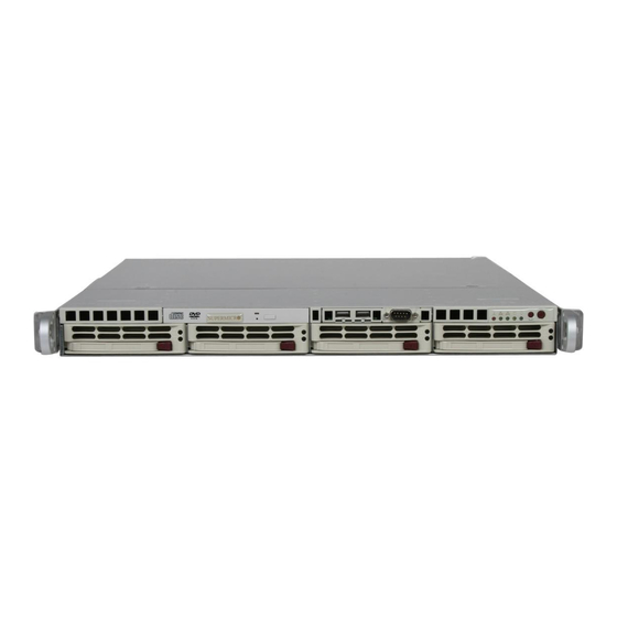
UPER ERVER 5015B-MT User's Manual Figure 6-1. Chassis Front View Figure 6-2. Chassis Rear View Control Panel The control panel (located on the front of the chassis) must be connected to the JF1 connector on the motherboard to provide you with system control buttons and status indicators. -
Page 59: System Fans
BIOS. System Fan Failure If a fan fails, you will need to have it replaced with the same type. Contact your vendor or Supermicro for information on replacement fans. Drive Bay Installation/Removal Removing the Front Bezel If your system has a front bezel (optional) attached to the chassis, you must fi... -
Page 60: Serial Ata Drive Installation
UPER ERVER 5015B-MT User's Manual Accessing the Drive Bays SATA Drives: Because of their hotswap capability, you do not need to access the inside of the chassis or power down the system to install or replace SATA drives. Proceed to the next step for instructions. Note: The operating system you use must have RAID support to enable the hot-swap capability of the SATA drives. -
Page 61: Serial Ata Backplane
Chapter 6: Advanced Chassis Setup Installing/Removing SATA Drives To remove a carrier, push the release button located beside the drive LEDs. Swing the colored handle fully out and use it to pull the unit straight out (see Figure 6-5). Note: Your operating system must have RAID support to enable the hot-plug ca- pability of the SATA drives. - Page 62 UPER ERVER 5015B-MT User's Manual DVD-ROM Drive Installation The top cover of the chassis must be opened to gain full access to the DVD-ROM drive bay. The 5015B-MT accomodates only slim DVD-ROM drives. Side mounting brackets are needed to mount a slim DVD-ROM drive into the 5015B-MT server.You must power down the system before installing or removing a DVD-ROM drive.
-
Page 63: Power Supply
Power Supply Failure If the power supply unit fails, the system will shut down and you will need to replace the power supply unit. Replacement units can be ordered directly from Supermicro (PWS-0054 - see contact infomation in Chapter 1). - Page 64 UPER ERVER 5015B-MT User's Manual Notes...
-
Page 65: Chapter 7 Bios
Warning: Do not shut down or reset the system while updating BIOS to prevent possible boot failure. Note: The SPI BIOS chip used in the X7SBi is not removable. To replace a dam- aged SPI BIOS chip, please send the motherboard to Supermicro for repair. -
Page 66: Running Setup
UPER ERVER 5015B-MT User's Manual Running Setup Default settings are in bold text unless otherwise noted. The BIOS setup options described in this section are selected by choosing the appropriate text from the main BIOS Setup screen. All displayed text is described in this section, although the screen display is often all you need to understand how to set the options (See the next page). -
Page 67: Main Bios Setup Menu
Chapter 7: BIOS Main BIOS Setup Menu Main Setup Features System Time To set the system date and time, key in the correct information in the appropriate fi elds. Then press the <Enter> key to save the data. System Date Using the arrow keys, highlight the month, day and year fi... - Page 68 UPER ERVER 5015B-MT User's Manual Serial ATA This setting allows the user to enable or disable the function of Serial ATA. The options are Disabled and Enabled. Native Mode Operation Select Serial ATA to use the SATA mode, or select Auto to use the Native Mode for ATA.
- Page 69 Chapter 7: BIOS Type This option allows the user to select the type of an IDE/SATA device. Select Auto to allow the BIOS to automatically confi gure the parameters of the IDE/ SATA device installed on a slot. Enter a number between 1 to 39 to select a predetermined IDE/SATA device.
- Page 70 UPER ERVER 5015B-MT User's Manual Transfer Mode This option allows the user to set the transfer mode. The options are Standard, Fast PIO1, Fast PIO2, Fast PIO3, Fast PIO4, FPIO3/DMA1 and FPIO4/DMA2. Ultra DMA Mode This option allows the user to confi gure the Ultra DMA Mode setting. The options are Disabled, Mode 0, Mode 1, Mode 2, Mode 3, Mode 4, and Mode 5.
-
Page 71: Advanced Setup
Chapter 7: BIOS Transfer Mode This option allows the user to set the transfer mode. The options are Standard, Fast PIO1, Fast PIO2, Fast PIO3, Fast PIO4, FPIO3/DMA1 and FPIO4/DMA2. Ultra DMA Mode This option allows the user to confi gure the Ultra DMA Mode setting. The options are Disabled, Mode 0, Mode 1, Mode 2, Mode 3, Mode 4, and Mode 5. - Page 72 UPER ERVER 5015B-MT User's Manual ACPI Mode Select Yes to use the ACPI (Advanced Confi guration and Power Interface) power management feature on your system. The options are Yes and No. Power Button Behavior If set to Instant-Off, the system will power on or power off immediately as soon as the user hits the power button.
- Page 73 Chapter 7: BIOS Frequency Ratio (Available when supported by the CPU.) The feature allows the user to set the internal frequency multiplier for the CPU. The default setting is Default. Frequency High Ratio (Available when supported by the CPU.) The feature allows the user to set high ratio internal frequency multiplier for Intel SpeedStep CPUs.
- Page 74 UPER ERVER 5015B-MT User's Manual Set Maximum Ext. CPUID=3 When set to Enabled, the Maximum Extended CPUID will be set to 3. The options are Disabled and Enabled. Echo TPR Set to Enabled to prevent xTPR messages from being sent to the system.The options are Disabled and Enabled.
- Page 75 Chapter 7: BIOS Warning : Take Caution when changing the Advanced settings. An incor- rect value, a very high DRAM frequency, or an incorrect DRAM timing may cause the system to become unstable. When this occurs, reset the setting to the default setting. Memory Reclaiming Select Enable to enable the functionality of Memory Remapping above 4GB.
- Page 76 UPER ERVER 5015B-MT User's Manual Memory Cache Cache System BIOS Area This setting allows you to designate a reserve area in the system memory to be used as a System BIOS buffer to allow the BIOS to write (cache) data into this reserved memory area.
- Page 77 Chapter 7: BIOS Cache Extended Memory If enabled, this feature will allow the data stored in the extended memory area to be cached (written) into a buffer, a storage area in the Static DROM (SDROM) or written into the L1, L2, L3 cache inside the CPU to speed up CPU operations. Select Uncached to disable this function.
- Page 78 UPER ERVER 5015B-MT User's Manual PCI-X 133 MHz Slot Access the submenu for each of the settings above to make changes to the following: Option ROM Scan When enabled, this setting will initialize the device expansion ROM. The options are Enabled and Disabled. Enable Master This setting allows you to enable the selected device as the PCI bus master.
- Page 79 Chapter 7: BIOS Onboard LAN 1/Onboard LAN 2 Access the submenu for each of the settings above to make changes to the following: Option ROM Scan When enabled, this setting will initialize the device expansion ROM. The options are Enabled and Disabled. Enable Master This setting allows you to enable the selected device as the PCI bus master.
- Page 80 UPER ERVER 5015B-MT User's Manual Mode This setting allows you to set the type of device that will be connected to Serial Port B. The options are Normal and IR (for an infrared device). Base I/O Address This setting allows you to select the base I/O address for Serial Port B. The options are 3F8, 2F8, 3E8 and 2E8.
- Page 81 Chapter 7: BIOS DMI Event Logging Access the submenu to make changes to the following settings. Event Log Validity This is a display to inform you of the event log validity. It is not a setting. Event Log Capacity This is a display to inform you of the event log capacity. It is not a setting. View DMI Event Log Highlight this item and press <Enter>...
- Page 82 UPER ERVER 5015B-MT User's Manual Console Redirection Access the submenu to make changes to the following settings. COM Port Address This item allows you to specify which COM port to direct the remote console to: Onboard COM A or Onboard COM B. This setting can also be Disabled. BAUD Rate This item allows you to set the BAUD rate for the console redirection.
- Page 83 Chapter 7: BIOS Hardware Monitoring CPU Temperature CPU Overheat Temperature This option indicates the CPU temperature overheat threshold that will activate the alarm system when the CPU temperature reaches this pre-set temperature threshold. The options are 75 C, 80 C, 85 C, and 90 C (Note) Highlight this and hit <Enter>...
- Page 84 UPER ERVER 5015B-MT User's Manual IPMI (The option is available only when an IPMI card is installed in the system.) IPMI Specifi cation Version: This item displays the current IPMI Version. Firmware Version: This item displays the current Firmware Version. System Event Logging Select Enabled to enable IPMI Event Logging.
- Page 85 Chapter 7: BIOS OS Boot Watch Dog Set to Enabled to enable OS Boot Watch Dog. The options are Enabled and Disabled. Timer for Loading OS (Minutes) This feature allows the user to set the time value (in minutes) for the previous item: OS Boot Watch Dog by keying-in a desired number in the blank.
- Page 86 UPER ERVER 5015B-MT User's Manual Realtime Sensor Data This feature display information from motherboard sensors, such as temperatures, fan speeds and voltages of various components. 7-22...
-
Page 87: Security Settings
Chapter 7: BIOS Security Settings Choose Security from the Phoenix BIOS Setup Utility main menu with the arrow keys. You should see the following display. Security setting options are displayed by highlighting the setting using the arrow keys and pressing <Enter>. All Security BIOS settings are described in this section. - Page 88 UPER ERVER 5015B-MT User's Manual Fixed Disk Boot Sector Select Normal to enable the feature of Write-Protect to protect the boot sector on the hard drives from virus intrusion. Password on Boot When set to Enabled, a user will need to key-in a password to enter the system at system boot.
-
Page 89: Boot Settings
Chapter 7: BIOS Boot Settings Choose Boot from the Phoenix BIOS Setup Utility main menu with the arrow keys. You should see the following display. See details on how to change the order and specs of boot devices in the Item Specifi c Help window. All Boot BIOS settings are described in this section. -
Page 90: Exit
UPER ERVER 5015B-MT User's Manual Exit Choose Exit from the Phoenix BIOS Setup Utility main menu with the arrow keys. You should see the following display. All Exit BIOS settings are described in this section. Exit Saving Changes Highlight this item and hit <Enter> to save any changes you made and to exit the BIOS Setup utility. -
Page 91: Appendix A Bios Post Messages
Appendix A: BIOS POST Messages Appendix A BIOS POST Messages During the Power-On Self-Test (POST), the BIOS will check for problems. If a problem is found, the BIOS will activate an alarm, turn on LED indicators or display a message as listed below. Failure Fixed Disk Fixed disk is not working or not confi... - Page 92 UPER ERVER 5015B-MT User's Manual System CMOS checksum bad - Default confi guration used System CMOS has been corrupted or modifi ed incorrectly, perhaps by an applica- tion program that changes data stored in CMOS. The BIOS installed Default Setup Values.
- Page 93 Appendix A: BIOS POST Messages System cache error - Cache disabled RAM cache failed and BIOS disabled the cache. On older boards, check the cache jumpers. You may have to replace the cache. See your dealer. A disabled cache slows system performance considerably. CPU ID: CPU socket number for Multi-Processor error.
- Page 94 UPER ERVER 5015B-MT User's Manual Fixed Disk n Fixed disk n (0-3) identifi ed. Invalid System Confi guration Data Problem with NVRAM (CMOS) data. I/O device IRQ confl ict I/O device IRQ confl ict error. PS/2 Mouse Boot Summary Screen: PS/2 Mouse installed.
- Page 95 Appendix A: BIOS POST Messages Parity Check 2 nnnn Parity error found in the I/O bus. BIOS attempts to locate the address and display it on the screen. If it cannot locate the address, it displays ????. Press <F1> to resume, <F2> to Setup, <F3> for previous Displayed after any recoverable error message.
- Page 96 UPER ERVER 5015B-MT User's Manual Notes...
-
Page 97: Appendix B Bios Post Codes
Appendix B: BIOS POST Codes Appendix B BIOS POST Codes This section lists the POST (Power On Self Test) codes for the Phoenix BIOS. POST codes are divided into two categories: recoverable and terminal. Recoverable POST Errors When a recoverable type of error occurs during POST, the BIOS will display an POST code that describes the problem. - Page 98 UPER ERVER 5015B-MT User's Manual POST Code Description 8254 timer initialization 8237 DMA controller initialization Reset Programmable Interrupt Controller 1-3-1-1 Test DRAM refresh 1-3-1-3 Test 8742 Keyboard Controller Set ES segment register to 4 GB Auto size DRAM Initialize POST Memory Manager Clear 512 kB base RAM 1-3-4-1 RAM failure on address line xxxx* 1-3-4-3 RAM failure on data bits xxxx* of low byte of...
- Page 99 Appendix B: BIOS POST Codes POST Code Description Test RAM between 512 and 640 kB Test extended memory Test extended memory address lines Jump to UserPatch1 Confi gure advanced cache registers Initialize Multi Processor APIC Enable external and CPU caches Setup System Management Mode (SMM) area Display external L2 cache size Load custom defaults (optional)
- Page 100 UPER ERVER 5015B-MT User's Manual POST Code Description Check for SMART Drive (optional) Shadow option ROMs Set up Power Management Initialize security engine (optional) Enable hardware interrupts Determine number of ATA and SCSI drives Set time of day Check key lock Initialize typematic rate Erase F2 prompt Scan for F2 key stroke...
- Page 101 Appendix B: BIOS POST Codes POST Code Description Re-map I/O and memory for PCMCIA Initialize digitizer and display message Unknown interrupt The following are for boot block in Flash ROM POST Code Description Initialize the chipset Initialize the bridge Initialize the CPU Initialize system timer Initialize system I/O Check force recovery boot...
- Page 102 UPER ERVER 5015B-MT User's Manual Notes...
-
Page 103: Appendix C System Specifi Cations
Appendix C: System Specifi cations Appendix C System Specifi cations Processors Single Intel Xeon 3200/3000 Series LGA775 processors at system bus speeds of 1333, 1066 and 800 MHz Note: Please refer to the motherboard specifi cations pages on our web site for updates on supported processors. - Page 104 UPER ERVER 5015B-MT User's Manual Chassis Model: SC813MTQ-300C (1U Rackmount) Dimensions: (WxHxD) 17.2 x 1.7 x 19.85 in. (437 x 43 x 504 mm) Note: please visit our web site for information on supported operating systems Weight Gross Weight: 38 lbs. (17.3 kg.) System Cooling Four (4) 4-cm high performance fans System Input Requirements...
- Page 105 Appendix C: System Specifi cations California Best Management Practices Regulations for Perchlorate Materials: This Perchlorate warning applies only to products containing CR (Manganese Dioxide) Lithium coin cells. “Perchlorate Material-special handling may apply. See www.dtsc.ca.gov/hazardouswaste/perchlorate”...
- Page 106 ERVER 5015B-MT User's Manual (continued from front) The products sold by Supermicro are not intended for and will not be used in life support systems, medical equipment, nuclear facilities or systems, aircraft, aircraft devices, aircraft/emergency com- munication devices or other critical systems whose failure to perform be reasonably expected to result in signifi...