
Related Manuals for Siemens EC645HB90A


Summary of Contents for Siemens EC645HB90A
- Page 1 This cooktop is for use with Natural Gas and Universal LPG EC645HB90A EC745RT90A Siemens - Electrogeräte GmbH Carl-Wery-Straß e 34 81739 München Cod. 9000532685 A www.siemens-home.com...
-
Page 2: Table Of Contents
Content Safety considerations ........5 For your safety . - Page 3 Dear customer, Congratulations on your choice and thank you for purchasing one of our appliances. This practical, modern and functional appliance is manufactured using materials of the highest quality which are subject to strict quality control checks throughout the entire manufacturing process.
-
Page 4: Safety Considerations
Safety considerations For your safety If the information in this manual is not followed exactly, a fire or explosion may result causing property damage, personal injury or death. Do not store articles on or against this appliance. Do not store flammable material near this appliance. Do not spray aerosols in the vicinity of this appliance while it is in operation. - Page 5 Important. When using a very large pot, leave a gap of at least 50 mm (2”) to avoid damaging any parts in bench top wood, plastic or other non-heat resistant materials. Never leave oil or hot fat unattended. The surfaces on heating and cooking appliances get hot when in use.
-
Page 6: Installation
Installation Statutory This installation must conform with the following: requirements Manufacturer’s Installation instructions Ø Local Gas Fitting Regulations Ø Municipal Building Codes, Ø Refer to AS/NZS 5601.1 for Gas Installations. Ø S.A.A. Wiring Code Ø Local Electrical Regulations Ø Any other statutory regulations Ø... -
Page 7: Clearances
Fig. 1a Before connecting the unit, check whether the local connection conditions (type of gas) are compatible with the unit’s setting. Observe any special conditions imposed by local suppliers (utilities). The specifications of this cooktop are stated on the data label located on the bottom of the cooktop base. -
Page 8: Installation Of Cooktop Into The Kitchen Bench
If the base of the hotplate can be touched, a protecting shield must be fitted. This shield must be at least 10 mm from the lowest part of the hotplate and must be capable of withstanding the appliance temperatures. Minimum thickness of benchtop is 30 mm. -
Page 9: Connection
Connection Electrical An electrical 10 amp socket needs to be within 1 m of the hotplate to allow electrical connection. The socket must Fig. 4 remain accessible after installation of the appliance. Important note: This appliance is connected to the mains (240 VAC) by means of the connecting lead which must be fixed to the kitchen unit to prevent it from coming into contact with hot parts of the cooktop (or an oven installed underneath) - Page 10 Fig. 5 Fig. 6 There are two ways to carry out the connection to the main gas line: A. The hotplate can be connected with rigid pipe as specified in AS/NZS 5601.1 B. Flexible Hose: If installing with a hose assembly, install with a hose assembly that complies with AS/NZS 1869 (AGA Approved), 10 mm ID, class Bor D, no more than 1,2 m long and in accordance with AS/NZS 5601.1.
-
Page 11: Conversion From Nat. Gas To Universal Lpg
Converting the cooktop from Nat. Gas to Universal LPG To change injectors All work involved in installation, setting and adaptation to a different gas type must be carried out by authorised personnel from our Service Centre and must comply with current regulations and the conditions laid down by the local gas company. -
Page 12: Adjustment Of The Taps
Ensure that it is completely tightened in order to guarantee the seal. Fig. 8 Adjustment of the Set the control knobs to minimum. Remove the control knobs from the taps. Fig. 9. taps It has a flexible rubber valve reinforcing ring. Simply press on this seal with the tip of a screwdriver to allow access to the tap adjusting screw. - Page 13 - Remove all the burner covers, pan supports and control knobs. - Loosen the screws on the burners. Use the disassembly lever 483196 availablle from our Technical Assistance Service. To release the front clips, apply the lever to the area shown in figure 10. Fig.
-
Page 14: Operating Instructions
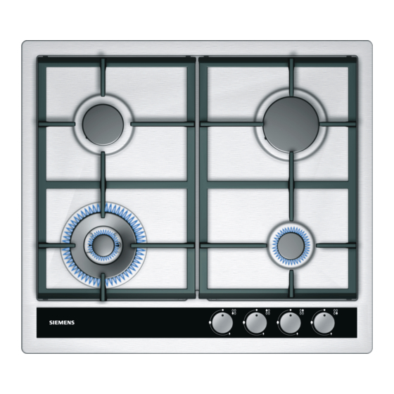
Operating instructions Burner locations Pan supports Control knobs Auxiliary burner (up to 1 kW) Semi-rapid burner (up to 1,75 kW) Rapid burner (up to 3 kW) Double-flame burner (up to 3,3 kW) Double-flame burner (up to 5 kW) Timer The gas burners There are indications to show which burner each control knob operates. -
Page 15: Switching On Automatically
Switching on If your cooktop can be switched on automatically (ignition sparkers): automatically 1. Press the chosen burner control knob and turn it anticlockwise to the maximum power setting. While the control knob is still pressed down, sparks are produced on all burners. The flame ignites (it is no longer necessary to press down the control knob). -
Page 16: Warnings
Outer flame on minimum, inner flame on full power. Inner flame on full power. Inner flame on minimum power. Warnings It is normal to hear a slight whistling noise while the burner is operating. When it is first used, it is normal for the burner to give off odours;... -
Page 17: Suitable Pans
The use of a cooktop leads to the production of heat and moisture in the kitchen. For this reason make sure that the room is properly ventilated. Keep natural ventilation openings, such as windows, open or provide a mechanical ventilation device (e.g. a range hood or overhead exhaust fan). -
Page 18: Cooking Recommendation
Cooking recommendation Very high, high Medium Double flame Boiling, grilling, Reheating and keeping things hot: burner browning and cooked and pre-cooked dishes. Asian food (wok). Rapid burner Steaks, omelettes, Rice, white sauce Steaming and frying. and ragout. vegetables. Semi-rapid burner Steaming potatoes, Reheating, keeping things hot and fresh vegetables,... -
Page 19: Countdown Timer
Countdown timer You can use this function to programme a time of up to 99 minutes. This service may be used independently of other services. THE COUNTDOWN TIMER DOES NOT TURN OFF ANY BURNER. Programming procedure 1. Touch the 0 symbol once. The display will show the following image: ‹‹... -
Page 20: Other Functions
The display will always show the time remaining for the first programme to finish. When the programmed time When the programmed time has elapsed, the burner has elapsed goes out, a beep sounds for 30 seconds, ‹‹ is shown Ú on the right of the display and on the left the dots move around. -
Page 21: The Digital Display
Protection against power If your timer has a programme in progress and there is a failures power failure, the programmed burners will be turned off as a means of protection. As soon as the power supply returns, the display will show the ˜‹ message. To be able to use the timer once more, touch any of the symbols and the display will turn off and your hob will be ready to be programmed. -
Page 22: Precautions For Use
Precautions for use The following advice is intended to help you save energy and prevent pan damage: Use pans which are the right size for each burner. Do not use small pans on large burners. The flame should not touch the sides of the pan. Do not use damaged pans, which do not sit evenly on the cooktop. -
Page 23: Cleaning And Maintenance
Cleaning and maintenance Cleaning Once the appliance is cool, use a sponge to clean it with soap and water. After each use, clean the surface of the respective burner parts once they have cooled down. If any residue is left (baked-on food, drops of grease etc.), however little, it will become stuck to the surface and more difficult to remove later. -
Page 24: Service
Service DO NOT MODIFY THIS APPLIANCE. Only authorized personnel from the Service Centre are qualified to work on the appliance. Sometimes certain faults detected can be easily resolved. Before calling the Service Centre, bear in mind the following advice: Fault Possible cause Solution The general electrical... -
Page 25: Wiring Diagram
Wiring diagram A. Switch B. Blue wire C. Brown wire D. Terminal E. Ignition module S iemens-Electrogeräte Gmb H S iemens-Electrogeräte Gmb H EC645HB90A EC745RT90A ULPG ULPG Test point pressure (kPa) Test point pressure (kPa) Injectors marks Injectors marks 85/140...