Table of Contents
Advertisement
Advertisement
Table of Contents

Related Manuals for SoundCraft FX16II


Summary of Contents for SoundCraft FX16II
-
Page 1: User Guide
USER GUIDE... - Page 2 Soundcraft shall not be liable for any loss or damage whatsoever arising from the use of information or any error contained in this manual.
-
Page 3: Table Of Contents
Contents SAFETY SYMBOL GUIDE IMPORTANT SAFETY INSTRUCTIONS INTRODUCTION BLOCK DIAGRAM WIRING UP CONSOLE CONTROLS Lexicon® FX PROCESSOR USING YOUR CONSOLE APPLICATIONS MARKUP SHEET TYPICAL CONNECTING LEADS REPOSITIONING THE REAR PANEL FOR RACKMOUNTING DIMENSIONS FX16ii TYPICAL SPECIFICATIONS WARRANTY... -
Page 5: Safety Symbol Guide
SAFETY SYMBOL GUIDE For your own safety and to avoid invalidation of the warranty all text marked with these symbols should be read carefully. WARNINGS The lightning flash with arrowhead symbol, is intended to alert the user to the presence of un-insulated “dangerous voltage”... -
Page 6: Important Safety Instructions
Note: It is recommended that all maintenance and service on the product should be carried out by Soundcraft or its authorised agents. Soundcraft cannot accept any liability whatsoever for any loss or damage caused by service, maintenance or repair by unauthorised personnel. - Page 7 No naked flame sources, such as lighted candles, should be placed on the apparatus. Ventilation should not be impeded by covering the ventilation openings with items such as newspapers, table cloths, curtains etc. THIS APPARATUS MUST BE EARTHED. Under no circumstances should the safety earth be disconnected from the mains lead.
-
Page 8: Introduction
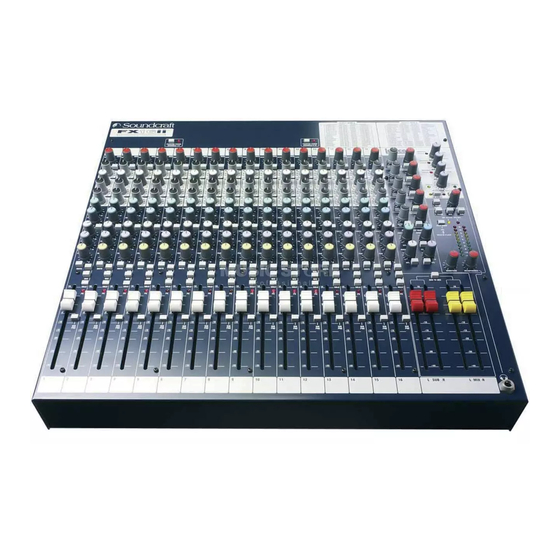
Built to the highest standards using quality components and surface mount technology, the FX16ii is designed to be as easy to use as possible. We have spent years researching the most efficient methods of control for two key reasons: 1) Engineers, musicians, writers and programmers all need to have very few interruptions to the creative process;... -
Page 9: Block Diagram
BLOCK DIAGRAM... -
Page 10: Wiring Up
WIRING UP Mic Input The MIC input accepts XLR-type connectors and is designed to suit a wide range of BALANCED or UNBALANCED low-level signals, whether from delicate vocals requiring the best low-noise performance, or drum kits needing maximum headroom. Professional dynamic, condenser or ribbon mics are best because these will be LOW IMPEDANCE. - Page 11 A ‘Y’ lead may be required to connect to equipment with separate send and return jacks as shown below: Stereo Returns 1 - 4 These accept 3-pole 6.35mm (1/4") jacks, or 2-pole mono jacks which will automatically ground the ‘cold’ input. Use these inputs for sources such as keyboards, drum machines, synths, tape machines or as returns from processing units.
- Page 12 Polarity (Phase) You will probably be familiar with the concept of polarity in electrical signals and this is of particular importance to balanced audio signals. Just as a balanced signal is highly effective at cancelling out unwanted interference, so two microphones picking up the same signal can cancel out, or cause serious degradation of the signal if one of the cables has the +ve and -ve wires reversed.
- Page 13 Customers outside the UK are requested to contact their territorial distributor who is able to offer support in the local time zone and language. Please see the distributor listings on our website (www.soundcraft.com) to locate your local distributor. OUT-OF-WARRANTY PRODUCTS For out-of-warranty consoles purchased in the United Kingdom, please contact the Customer Services Department (e-mail: csd@soundcraft.com) at the factory in Potters...
-
Page 14: Console Controls
CONSOLE CONTROLS INPUT CHANNEL 1 Mic Input (Rear Connector Panel) The mic input accepts XLR-type connectors and is designed to suit a wide range of BALANCED or UNBALANCED signals. Professional dynamic, condenser or ribbon mics are best because these will be LOW IMPEDANCE. You can use low-cost HIGH IMPEDANCE mics, but the level of background noise will be higher. - Page 15 level to the output of the mixer. Note that some sound equipment, particularly that intended for domestic use, operates at a lower level (- 10dBV) than professional equipment and will therefore need a higher gain setting to give the same output level.
- Page 16 PAN control. 13 SOLO/PK The FX16ii provides versatile non-destructive PFL (Pre-Fade-Listen) and SOLO- IN-PLACE monitoring, as selected by the SOLO MODE switch on the Master section.
- Page 17 14 FADER The 100mm FADER allows precise balancing of the various source signals being mixed to the selected outputs. You get most control when the input Sensitivity is set up correctly, giving full travel on the fader. See the ‘Initial Setup’ section on page 31 for help in setting a suitable signal level. 15 DIRECT OUTPUT (Rear Connector Panel) Each channel has a dedicated Direct Output which allows direct connection to external devices, for example to feed Tape Machines or effects units.
- Page 18 MASTER SECTION...
- Page 19 1 AUX MASTERS Each of the three AUX outputs has a master level control which sets the output level of the combined Aux signals from the channels, and an associated AFL switch. Just as the Channel PFL switches allow pre-fade listening, so you can monitor each AUX output after the level control by pressing the AFL switch (when PFL mode is selected by the SOLOMODE switch), allowing you to determine what level is leaving the output connector.
- Page 20 8 STEREO RETURNS Four balanced Stereo Returns are available for the outputs of effects units or other stereo sources and are mixed directly to the AUX and/or MIX/SUB busses at a level set by the respective controls. The left-hand control sets the level to a choice of AUX 1 or AUX 2 (AUX 3 or FX in the case of RET 4), depending on the postion of the adjacent switch.
- Page 21 When any SOLO or AFL switch is pressed, the L & R meters automatically switch to show the selected PFL/AFL signal on both meters, in mono. 16 MONITOR SOURCE SELECT These switches allow a choice source for the Phones, Monitor outputs and meters. Normally the monitor source is either MIX or SUB (or both, depending on which of the two right-hand switches is selected), but pressing the 2TK switch swaps the monitoring to the 2 Track input.
-
Page 22: Lexicon® Fx Processor
Lexicon® FX PROCESSOR The effects within the console have been designed with both live sound reinforcement and home recording in mind. Featuring the deep, rich reverb algorithms that Lexicon® are renowned for the effects processor offers increased versatility and high quality effects, all instantly accessible via the extremely intuitive front panel controls. -
Page 23: Fx Processor Controls
FX PROCESSOR CONTROLS 20 Tap Tempo Button - Tapping this button twice sets the Delay Time of the selected program. The LED flashes to indicate current tempo. Can be tapped in time with music source to synchronise the delay. 21 Store Button - Stores program modifications to one of the program locations. Press and hold for three seconds will store the preset in the current location. -
Page 24: Reverbs
REVERBS Reverberation (or “reverb” for short) is the complex effect created by the way we perceive sound in an enclosed space. When sound waves encounter an object or boundary, they don’t just stop. Some of the sound is absorbed by the object, but most of the sound is reflected or is diffused. In an enclosed space, reverb is dependent on many features of that space, including the size, shape and the type of materials that line the walls. -
Page 25: Reverb Controls
(essentially the tail of the reverb) heard first, and then grows louder over time until they abruptly cut off. Ambience Reverb Ambience is used to simulate the effect of a small or medium sized room without noticeable decay. It is often used for voice, guitar or percussion. -
Page 26: Delay Controls
Boing This is a unique parameter to the Spring reverb, designed to increase or decrease the amount of spring rattle that is a physical characteristic of spring tank reverbs. DELAYS Delays repeat a sound a short time after it first occurs. Delay becomes echo when the output is fed back into the input (feedback). -
Page 27: Modulated Effects
more repeats; lower settings reduce the number of repeats. When this knob is turned fully clockwise, it engages Repeat Hold – delay repeats play back in an infinite loop, but no further input signal is introduced into the delay effect. Repeat Hold is available only on Studio, Digital and Pong Delay. Ducker Threshold Studio and Digital delays offer a “ducking”... - Page 28 Flanger This effect was originally created by simultaneously recording and playing back two identical programs on two tape recorders, then using hand pressure against the flange of the tape reels to slow down first one machine, then the other. The result was a series of changing phase cancellations and reinforcements, with characteristic swishing, tunneling, and fading sounds.
- Page 29 Vibrato Vibrato is obtained by smoothly varying the pitch of the signal just sharp and flat of the original at a determined rate. Vibrato Stereo (Wet only) Rotary Mono (Wet only) Tremolo/Pan Stereo (Wet only) Adjust 1: Speed Controls the modulation rate of Vibrato. Adjust 2: Depth Controls the maximum amount of pitch shift.
- Page 30 EFFECTS DATA CHART...
-
Page 31: Using Your Console
USING YOUR CONSOLE The final output from your sound system can only ever be as good as the weakest link in the chain, and especially important is the quality of the source signal because this is the starting point of the chain. Just as you need to become familiar with the control functions of your mixer, so you must recognise the importance of correct choice of inputs, microphone placement and input channel settings. - Page 32 channels are added to the mix, the meters may move into the red section. Adjust the overall level using the Master Faders if necessary. • Listen carefully for the characteristic sound of “feedback”. If you cannot achieve satisfactory input level setting without feedback, check microphone and speaker placement and repeat the exercise.
-
Page 33: Applications
APPLICATIONS APPLICATION 1 - LIVE SOUND REINFORCEMENT... - Page 34 APPLICATION 2 - RECORDING...
- Page 35 APPLICATION 3 - INSTALLATION...
- Page 36 APPLICATION 4 - PLACE OF WORSHIP...
- Page 38 APPLICATION 6 - POST-PRODUCTION VIDEO EDITING...
- Page 39 APPLICATION 7 - MULTIMEDIA...
- Page 40 APPLICATION 8 - CONFERENCE PA...
-
Page 41: Markup Sheet
MARKUP SHEET You may freely copy this page, and use it to record the settings used for particular applications/gigs. -
Page 42: Typical Connecting Leads
TYPICAL CONNECTING LEADS... -
Page 44: Repositioning The Rear Panel For Rackmounting
REPOSITIONING THE REAR PANEL FOR RACKMOUNTING... -
Page 45: Dimensions
DIMENSIONS... -
Page 46: Fx16Ii Typical Specifications
FX16ii TYPICAL SPECIFICATIONS Frequency Response Mic / Line Input to any Output ..........+/-1dB, 20Hz – 20kHz T.H.D. Mic Sensitivity -30dBu, +14dBu @ Mix output ........< 0.09% @ 1kHz Noise Mic Input E.I.N. (maximum gain) ......………..-127dBu (150Ω source) Aux, Mix and Masters (@ 0dB, faders down)........………< -84dBu Crosstalk (@ 1kHz) Channel Mute....................>... -
Page 47: Warranty
End User means the person who first puts the equipment into regular operation. Dealer means the person other than Soundcraft (if any) from whom the End User purchased the Equipment, provided such a person is authorised for this purpose by Soundcraft or its accredited Distributor.