Table of Contents
Advertisement
Advertisement
Table of Contents

Related Manuals for SoundCraft LX7II


Summary of Contents for SoundCraft LX7II
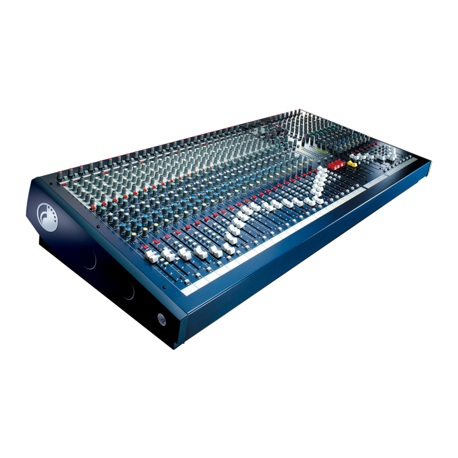
- Page 1 User Guide User Guide User Guide User Guide User Guide...
- Page 2 Soundcraft shall not be liable for any loss or damage whatsoever arising from the use of information or any error contained in this manual.
-
Page 3: Table Of Contents
Contents Contents Contents Contents Contents INTRODUCTION INTRODUCTION 5 5 5 5 5 INTRODUCTION INTRODUCTION INTRODUCTION Featur Features Featur 6 6 6 6 6 Featur Featur W W W W W ar ar ar ar arranty ranty ranty ranty ranty 7 7 7 7 7 INST INST ALLA... -
Page 5: Introduction
INTRODUCTION INTRODUCTION INTRODUCTION INTRODUCTION INTRODUCTION... -
Page 6: Featur Features Featur Es
There are also 8, 16 or 24 direct outs, depending on the frame size of your console. LX7-II’s balanced mic inputs all use Soundcraft new GB30 padless mic preamp providing 60dB of gain and 22dBu of headroom. Each input also includes 4 band EQ with two swept mid frequency controls. In addition, EQ In/Out switch and steep 18dB/Octave High Pass Filter, allow effective audio control in difficult venues whilst the six auxiliary sends are pre-post switchable in pairs from each channel, providing a maximum of 4 pre-fader and six post-fader. -
Page 7: W W W W W Ar Ar Ar Ar Arranty
Equipment has been properly installed in accordance with instructions contained in Soundcraft's manual; and b) the End User has notified Soundcraft or the Dealer within 14 days of the defect appear- ing; and c) no persons other than authorised representatives of Soundcraft or the Dealer have effected any replacement of parts maintenance adjustments or repairs to the Equipment;... -
Page 9: Inst Installa Inst Alla Allation Alla Tion
INST INST ALLA ALLA TION TION INST ALLA ALLA TION TION INST INST ALLA TION For your own safety and to avoid invalidation of the warranty please read this section carefully. -
Page 10: W W W W W Arning
To avoid the risk of fire, replace the mains fuse only with the correct value fuse, as marked on the rear panel. The internal power supply unit contains no user serviceable parts. Refer all servicing to a qualified service engineer, through the appropriate Soundcraft dealer. -
Page 11: Pr Pr Pr Pr Precautions And Safety Instr Ecautions And Safety Instr Ecautions And Safety Instructions Uctions
General Wiring Procedures To take full advantage of the excellent signal to noise ratio and low distortion of Soundcraft consoles, care must be taken to ensure that incorrect installation and wiring does not degrade the performance of the desk. Hum, buzz, instability and Radio Frequency interference can usually be traced to earth loops and inferior earthing systems. -
Page 12: Initial Wiring Considerations
Initial Wiring Considerations For optimum performance, it is essential for the earthing system to be clean and noise free, as all signals are referenced to this earth. A central point should be decided on for the main earth point system, and all earths should be 'star fed' from this point. It is common electrical practice to `daisy chain' the earths to all electrical outlets but this method is unsuitable for audio installations. -
Page 13: Points To Remember
Points to Remember In all cases, use good quality twin screened audio cable. Check for instability at the output. Always connect both conductors at both ends, and ensure that the screen is only connected at one end. Do not disconnect the mains earth from each piece of equipment. This is needed to provide both safety and screen returns to the system star point. -
Page 14: Setting Up & Tr R R R R Oubleshooting Setting Up & T Setting Up & T Oubleshooting
Is the mains supply present? Is the mains lead firmly connected? Check the mains fusing If only one of the power indicators is illuminated, consult your Soundcraft dealer Condenser Mic N Condenser Mic N Condenser Mic No o o o o t W... - Page 15 Met t t t t er er er er ers no s no s no s not sho t sho t sho t showing an wing an wing an wing any signal y signal y signal y signal s no t sho wing an y signal...
-
Page 16: Connecting Leads
Connecting Leads Connecting Leads Connecting Leads Connecting Leads Connecting Leads... -
Page 17: Audio Connector Pinouts
Audio Connector Pinouts Audio Connector Pinouts Audio Connector Pinouts Audio Connector Pinouts Audio Connector Pinouts... -
Page 18: Dimensions
Dimensions Dimensions Dimensions Dimensions Dimensions... -
Page 19: Block Diagram
BLOCK DIAGRAM BLOCK DIAGRAM BLOCK DIAGRAM BLOCK DIAGRAM BLOCK DIAGRAM... -
Page 21: Using The Console
USING THE CONSOLE USING THE CONSOLE USING THE CONSOLE USING THE CONSOLE USING THE CONSOLE... -
Page 22: Overview
Overview A 16 channel frame is shown. -
Page 23: Mono Input Channel
Mono Input Channel 1 - MIC INPUT 1 - MIC INPUT 1 - MIC INPUT 1 - MIC INPUT 1 - MIC INPUT The mic input accepts XLR-type connectors and is designed to suit a wide range of BALANCED or UNBALANCED signals. Professional dynamic, condenser or ribbon mics are best because these will be LOW IMPEDANCE. - Page 24 4 - G 4 - G 4 - G 4 - G 4 - GAIN This knob sets how much of the source signal is sent to the rest of the mixer. Too high, and the signal will distort as it overloads the channel. Too low, and the level of any background hiss will be more noticeable and you may not be able to get enough signal level to the output of the mixer.
- Page 25 HF EQ HF EQ HF EQ HF EQ HF EQ Turn clockwise to boost high (treble) frequencies (12kHz and above) by up to 15dB, adding crispness to cymbals, vocals and electronic instruments. Turn anticlockwise to cut by up to 15dB, reducing hiss or excessive sibilance which can occur with certain types of microphone.
- Page 26 1 1 1 1 1 4 - F 4 - F 4 - FADER 4 - F ADER ADER ADER 4 - F ADER The 100mm FADER allows precise balancing of the various source signals being mixed to the Master Section. You get most control when the input Sensitivity is set up correctly, giving full travel on the fader.
-
Page 27: Stereo Input Channel
Stereo Input Channel 1 - INPUT J 1 - INPUT J 1 - INPUT J 1 - INPUT J 1 - INPUT JA A A A A CKS These high impedance inputs accept 3-pole `A’ gauge (TRS) jacks. Use these inputs for sources such as keyboards, drum machines, synths, tape machines or returns from processing units. -
Page 28: Master Section
Master Section 1 - A 1 - AUX MAS 1 - A UX MAS UX MAS UX MASTERS TERS TERS TERS 1 - A 1 - A UX MAS TERS Each of the six AUX outputs has a master output level control and associated AFL switch. - Page 29 8 - TB LEVEL 8 - TB LEVEL 8 - TB LEVEL 8 - TB LEVEL 8 - TB LEVEL A balanced input is provided for a Talkback microphone. The signal may be routed selectively to Aux 1/2 or 3/4 (which might typically be used for performers’ foldback) or Mix L/R by pressing the appropriate switches.
-
Page 30: Mark-Up Sheet
Mark-up Sheet You may freely copy this page to mark control positions to assist in resetting the desk between performances. -
Page 31: Specifica Specifications Specifica Tions
SPECIFICA SPECIFICA TIONS TIONS SPECIFICA TIONS TIONS SPECIFICA SPECIFICA TIONS Noise Noise Noise Noise Noise Measured RMS, 22Hz to 22kHz Bandwidth Mic E.I.N. @ unity gain,150W source impedance -129dBu Mix Output, 24 inputs routed to mix, faders at unity, muted <-80dBu Mix Output, 24 inputs routed to mix, faders down <-100dBu...