
Related Manuals for Sony UCP-8060E


Summary of Contents for Sony UCP-8060E
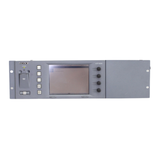
- Page 1 UNIVERSAL CONTROL PANEL UCP-8060 MAINTENANCE MANUAL 1st Edition Serial No. 10001 and Higher...
- Page 2 ! WARNING This manual is intended for qualified service personnel only. To reduce the risk of electric shock, fire or injury, do not perform any servicing other than that contained in the operating instructions unless you are qualified to do so. Refer all servicing to qualified service personnel.
- Page 3 For the U.S.A WARNING Attention-when the product is installed in Rack: This unit has no power switch. When installing the unit, incorporate a readily 1. Prevention against overloading of branch circuit accessible disconnect device in the fixed wiring, or When this product is installed in a rack and is connect the power cord to a socket-outlet which must supplied power from an outlet on the rack, please be provided near the unit and easily accessible, so that...
-
Page 5: Table Of Contents
Table of Contents Manual Structure Purpose of this manual ..................3 (E) Related manuals ....................3 (E) Contents ....................... 4 (E) Trademarks ......................4 (E) 1. Service Overview 1-1. Removing the Upper Panel ..............1-1 (E) 1-2. Main Parts Location ................1-1 (E) 1-3. - Page 6 3. Semiconductor Pin Assignments 4. Circuit Description and Overall Block Diagram 4-1. Circuit Description ................4-1 (E) 4-2. Overall Block Diagram ................4-2 5. Schematic Diagrams CN-2284 ....................5-1 CPU-352 ....................5-2 KY-537 ....................5-5 LED-397 ....................5-6 MB-978 ....................5-7 PS-635 ....................
-
Page 7: Manual Structure
..User’s Guide (Available on request) This manual describes the operations of the operation software. If this manual is required, please contact your local Sony Sales Office/Service Center..“Semiconductor Pin Assignments” CD-ROM (Available on request) This “Semiconductor Pin Assignments”... -
Page 8: Contents
Trademarks and registered trademarks used in this manual are follows. . Java is a registered trademark of Sun Microsystems, Inc.. . Memory Stick is a trademark of Sony Corporation. . MultiMediaCard is a trademark of Infineon Technologies AG. . TouchEngine is a trademark of Sony Corporation. -
Page 9: Service Overview
Section 1 Service Overview 1-1. Removing the Upper Panel 1-2. Main Parts Location KY-537 board 1. Remove the six screws, then remove the upper panel. LED-397 board 2. Disconnect one flexible flat cable from the connector TouchEngine board SW-1099 (CN101) on the MB-978 board. board MB-978 board CN101... -
Page 10: System Indicator And Status Indicator
1-3. System Indicator and Status Indicator 1-3. System Indicator and Status Indicator 1-3-1. System Indicator The system indicator mainly indicates the operation status of the hardware. The system indicator lights in red when the power is turned on. Generally it changes to amber soon, and then to green when the system normally starts. -
Page 11: Troubleshooting
1-3. System Indicator and Status Indicator 1-4. Troubleshooting When Memory Stick is used Green (lights): Indicates that the data is read to the Memory Stick Red (lights): Indicates that the data is written in the Memory Stick Amber (lights): Indicates that the system is in other operation 1-4. - Page 12 1-4. Troubleshooting Back light does not light. Status and possible cause Remedy Power is not turned on. Check if the power cord is connected. Back light is broken. If the system indicator lights in green, replace the back light. If the back light does not light after replacing the back light, replace the inverter unit.
- Page 13 1-4. Troubleshooting Jog roller, jog L button, or jog R button cannot be operated. Status and possible cause Remedy The connection between the SW-1099 board and Check the operation in the Self Diagnosis menu of the the SW-1098 board is not correct. SYSTEM SETUP UTILITY.
- Page 14 1-4. Troubleshooting The UCP-8060 cannot communicate via RS-232C. Status and possible cause Remedy Matching cable is not used. Check if the cross cable is used. Cross cable is broken. Check the cross cable. Communication conditions of PC are not correct. Correct the communication conditions of PC. RS-232C connector or communication IC is Check the communication status in the following procedure.
- Page 15 1-4. Troubleshooting Touch panel does not operate. Status and possible cause Remedy The connection between the MB-978 board Check the connection of the harness between the touch panel and and touch panel is not correct. the MB-978 board. If the connection is correct, replace the touch panel.
-
Page 16: Replacing The Board
1-4. Troubleshooting 1-5. Replacing the Board Back light is dark. Status and possible cause Remedy Brightness level of the back light is low. Check the brightness of LCD in the Device Control menu of the SYSTEM SETUP UTILITY and set to the level higher than the current level. - Page 17 1-5. Replacing the Board 1-5-2. CPU-352 Board 1-5-3. TouchEngine Board Before starting the replacement, be sure to pull out the Before starting the replacement, be sure to pull out the power plug from the wall outlet. power plug from the wall outlet. 1.
-
Page 18: Switching Regulator
1-5. Replacing the Board 1-6. Replacing the Main Parts 1-6. Replacing the Main Parts 4. Remove the two TouchEngine boards from the four bosses. 1-6-1. Switching Regulator Install the TouchEngine board with the piezoelectric actuator side up. Before starting the replacement, be sure to pull out the power plug from the wall outlet. -
Page 19: Rotary Encoder
1-6. Replacing the Main Parts 1-6-2. Rotary Encoder 5. Remove the five solders fixing the switching regulator. 6. Remove the switching regulator from the PS-635 board. Before starting the replacement, be sure to pull out the power plug from the wall outlet. Switching regulator 1. -
Page 20: Inverter Unit
1-6. Replacing the Main Parts 1-6-3. Inverter Unit 5. Remove the four nuts and four washers, then remove the VR mounting plate. 6. Remove the solder from the VR-282 board, then . Before starting the replacement, be sure to pull out the remove the rotary encoder. -
Page 21: Lcd Panel
1-6. Replacing the Main Parts 1-6-4. LCD Panel 6. Remove the four screws, then remove the LCD panel. 7. Remove the CN-2284 board from the LCD panel. B 3x6 Before starting the replacement, be sure to pull out the LCD panel power plug from the wall outlet. -
Page 22: Back Light
1-6. Replacing the Main Parts 1-6-5. Back Light 1-6-6. Touch Panel . Before starting the replacement, be sure to pull out the Before starting the replacement, be sure to pull out the power plug from the wall outlet. power plug from the wall outlet. . -
Page 23: Replacing The Fuse/Ic Link
EEPROM (IC204/CPU-352 board). A fuse and IC link are critical parts to safe operation. Required equipment Replace this component with Sony parts whose part . PC (with terminal software installed) numbers appear in this manual published by Sony. -
Page 24: System File Recovery
. Operation software (to be reinstalled after system file 7. Terminate the terminal software. recovery) To obtain the system file and operation software, contact your local Sony Sales Office/Service Center. Memory Stick slot Select L button Select R button Function button 2 Preparation 1. - Page 25 1-9. System File Recovery Installation (Update) 1. Remove the six screws, then open the upper panel. Do not disconnect the flexible flat cable connecting the PS-635 board and the MB-978 board. 2. Check that S201 (D-1) on the MB-798 board is set to 3.
-
Page 27: Spare Parts
Therefore, specified parts should be used in the case of replacement. 2. Standardization of Parts Some repair parts supplied by Sony differ from those used for the unit. These are because of parts common- ality and improvement. Parts list has the present standardized repair parts. -
Page 28: Exploded Views
Lower Panel Block 2-2. Exploded Views PSW 3x6 PS-635 Board B 4x6 B 3x5 B 3x5 Part No. SP Description B 3x5 1-468-486-11 s REGULATOR, SWITCHING (KWS15-5) 1-757-644-11 s CABLE, FLEXIBLE FLAT (30 CORE) 1-794-141-11 s INLET (WITH NOISE FILTER) B 4x6 3-364-990-01 s SCREW (M3X8) 3-370-475-01 s SCREW (+B) (3X6),NYLOCK... - Page 29 Front Panel Block LED-397 Board PSW 3x6 PSW 3x6 SW-1099 Board SW-1098 Board PSW 3x6 VR-282 Board PSW 3x6 PSW 3x6 Part No. SP Description X-3608-487-1 s ASSY,VOLUME KNOB 1-417-337-11 s PANEL, TOUCH 1-477-701-11 s ENCODER TYPE, OPTICS 1-761-651-11 s PWB, MOUNTED 1-823-558-11 s CABLE, FLEXIBLE FLAT (30CORE) 7-682-947-01 s SCREW +PSW 3X6 UCP-8060...
- Page 30 LCD Block B 3x6 B 3x6 CN-2284 Board PSW 3x6 PSW 3x6 KY-537 Board PSW 3x6 PSW 3x6 Part No. SP Description A-8345-525-A s MOUNTED CIRCUIT BOARD, CPU-352 A-8345-526-A s MOUNTED CIRCUIT BOARD, MB-978 1-477-607-11 s INVERTER UNIT (LCD MODULE) 1-757-273-11 s CABLE, FLEXIBLE FLAT (30 CORE) 1-805-059-11 s LCD MODULE 1-823-558-11 s CABLE, FLEXIBLE FLAT (30CORE)
-
Page 31: Electrical Parts List
2-3. Electrical Parts List ------------- ------------- CN-2284 BOARD CPU-352 BOARD ------------- ------------- Ref. No. Ref. No. or Q'ty Part No. SP Description or Q'ty Part No. SP Description CN304 1-573-370-21 s CONNECTOR, FFC/FPC 30P A-8345-525-A s MOUNTED CIRCUIT BOARD, CPU-352 CN801 1-779-396-11 o CONNECTOR, BOARD TO BOARD 31P C201... - Page 32 ------------ (CPU-352 BOARD) KY-537 BOARD ------------ Ref. No. Ref. No. or Q'ty Part No. SP Description or Q'ty Part No. SP Description IC201 8-759-584-62 s IC RQ5RW28BA-TR CN301 1-573-370-21 s CONNECTOR, FFC/FPC 30P IC202 6-703-172-01 s IC IM100-TQ144C IC203 6-703-134-01 s IC AT45DB321B-TI Q301 8-729-014-45 s TRANSISTOR RN1905-TE85R IC204...
- Page 33 ------------ MB-978 BOARD (MB-978 BOARD) ------------ Ref. No. Ref. No. or Q'ty Part No. SP Description or Q'ty Part No. SP Description A-8345-526-A s MOUNTED CIRCUIT BOARD, MB-978 C305 1-162-966-11 s CAPACITOR,CERAMIC 2200PF/50V B C306 1-126-391-11 s CAPACITOR ELECT 47MF/6.3V(105) C101 1-165-603-11 s CAPACITOR DOUBLE LAYERS 1.5F C307...
- Page 34 (MB-978 BOARD) (MB-978 BOARD) Ref. No. Ref. No. or Q'ty Part No. SP Description or Q'ty Part No. SP Description D307 8-719-420-90 s DIODE MA8051-M R305 1-218-855-11 s RESISTOR,CHIP 2.2K 1/10W(1608) D308 8-719-420-90 s DIODE MA8051-M R306 1-218-863-11 s RESISTOR,CHIP 4.7K 1/10W(1608) D309 8-719-420-90 s DIODE MA8051-M R307...
- Page 35 ------------ (MB-978 BOARD) PS-635 BOARD ------------ Ref. No. Ref. No. or Q'ty Part No. SP Description or Q'ty Part No. SP Description RB202 1-236-908-11 s RESISTOR,NETWORK 10K (3216) 2pcs 1-533-189-11 s HOLDER, FUSE RB301 1-233-576-11 s RESISTOR,CHIP NETWORK 100 2pcs 7-623-422-07 s WASHER LW 3 (TYPE 3) RB402 1-233-412-11 s RESISTOR,CHIP NETWORK 1K...
-
Page 36: Supplied Accessories List
------------- ----- SW-1098 BOARD FRAME ------------- ----- Ref. No. Ref. No. or Q'ty Part No. SP Description or Q'ty Part No. SP Description 1-572-474-11 s SWITCH, TACTILE 1-417-337-11 s PANEL, TOUCH 1-572-474-11 s SWITCH, TACTILE 1-477-607-11 s INVERTER UNIT (LCD MODULE) 1-757-273-11 s CABLE, FLEXIBLE FLAT (30 CORE) 1-757-644-11 s CABLE, FLEXIBLE FLAT (30 CORE) 2pcs... - Page 37 In addition, for semiconductors with ID Nos., refer to the separate CD-ROM titled “Semiconductor Pin Assignments” (Sony Part No. 9-968-546-xx) that allows searching for parts by semiconductor type or ID No. The semiconductors in the manual or on the CD-ROM are listed by equivalent types.
- Page 38 [|IC|] AT45DB321B-TI (ATMEL) SIGNAL SIGNAL SIGNAL 32M-BIT FLASH MEMORY —TOP VIEW— — MTEST — R.GND SIGNAL SIGNAL MRES1 — — BUSY — RDY/ — — MRES2 RESET — MRSTOUT — DD15 — MSDIN DD14 TENABLE — — MSDOUT DD13 — —...
- Page 39 LXT971ALC (LEVEL ONE) INPUTS ADDR0 - ADDR4 : ADDRESS DUAL SPEED ETHERNET TRANSCEIVER CFG0 - CFG3 : CONFIGURATION —TOP VIEW— : MANAGEMENT DATA CLOCK MDDIS : MANAGEMENT DISABLE PAUSE : PAUSE PWRDWN : POWER DOWN RBIAS : BIAS REFCLK : REFERENCE CLOCK RESET : RESET : SIGNAL DETECT...
- Page 40 MAX1771CSA-TP (MAXIM) RQ5RW28BA-TR (RICOH) STEP UP DC-DC CONTROLLER POSITIVE VOLTAGE REGULATOR —TOP VIEW— —TOP VIEW— INPUTS : CURRENT SENSE AMPLIFIER : FEED BACK SET SHDN : SHUTDOWN : POWER SUPPLY INPUT A.GND SHDN OUTPUTS : GATE DRIVE FOR EXTERNAL N-CHANNEL POWER TRANSISTOR : 1.5 V REFERENCE VOLTAGE DUAL-MODE COMPARATOR...
-
Page 41: Circuit Description And Overall Block Diagram
Section 4 Circuit Description and Overall Block Diagram 4-1. Circuit Description Memory On the CPU-352 board, three types of ICs (flash memory, RAM, and EEPROM) are used for memory. The UCP-8060 mainly consists of the following three boards. The capacity of flash memory (IC203) is 32 M bits. The flash memory stores programs, set data, and . -
Page 42: Overall Block Diagram
Overall Overall 4-2. Overall Block Diagram CPU-352 MB-978 EN201-EN204 IC202 VOL DATA ROTARY ENCODER IC205, IC206 +3.3V IC302 IC203 IC204 KNOB_AVAIL MRESET VR-282 PA0, 5-7 PA3, 4 (EDO) EEPROM FLASH IC304 MEMORY (I2C) DRAM_BUS TOUCH_D/A IC202 CN201 TOUCH PANEL PORT A SEL1 PB3-7 TOUCH_DATA... - Page 43 CN-2284 Section 5 Schematic Diagrams Index Board Name Function Page CN-2284 Relay Board (between MB-978 board and LCD module) CPU-352 System Control Board KY-537 Switch Board LED-397 LED Board MB-978 Motherboard PS-635 Power Supply Board 5-12 SW-1098 Switch and Relay Board (between 5-13 MB-978, SW-1099, LED-397 boards, and Memory Stick connector)
-
Page 44: Cpu-352
CPU-352 (1/3) CPU-352 (1/3) CPU-352 (1/3) BOARD NO. 1-686-381-11 LOT NO. 2C1- UCP-8060... - Page 45 CPU-352 (2/3) CPU-352 (2/3) CPU-352 (2/3) BOARD NO. 1-686-381-11 LOT NO. 2C1- UCP-8060...
- Page 46 CPU-352 (3/3) CPU-352 (3/3) CPU-352 (3/3) BOARD NO. 1-686-381-11 LOT NO. 2C1- UCP-8060...
- Page 47 KY-537 KY-537 KY-537 BOARD NO. 1-686-386-11 LOT NO. 2C1- UCP-8060...
-
Page 48: Led-397
LED-397 LED-397 LED-397 BOARD NO. 1-686-383-11 LOT NO. 2C1- UCP-8060... - Page 49 MB-978 (1/5) MB-978 (1/5) MB-978 (1/5) BOARD NO. 1-686-384-11 LOT NO. 2C1- UCP-8060...
- Page 50 MB-978 (2/5) MB-978 (2/5) MB-978 (2/5) BOARD NO. 1-686-384-11 LOT NO. 2C1- UCP-8060...
- Page 51 MB-978 (3/5) MB-978 (3/5) MB-978 (3/5) BOARD NO. 1-686-384-11 LOT NO. 2C1- UCP-8060...
- Page 52 MB-978 (4/5) MB-978 (4/5) MB-978 (4/5) BOARD NO. 1-686-384-11 LOT NO. 2C1- 5-10 5-10 UCP-8060...
- Page 53 MB-978 (5/5) MB-978 (5/5) MB-978 (5/5) BOARD NO. 1-686-384-11 LOT NO. 2C1- 5-11 5-11 UCP-8060...
- Page 54 PS-635 PS-635 PS-635 BOARD NO. 1-686-387-11 LOT NO. 2C1- 5-12 5-12 UCP-8060...
- Page 55 SW-1098, SW-1099 SW-1098, SW-1099 SW-1099 BOARD NO. 1-686-385-11 LOT NO. 2C1- SW-1098 BOARD NO. 1-686-389-11 LOT NO. 2C1- 5-13 5-13 UCP-8060...
- Page 56 VR-282 VR-282 VR-282 BOARD NO. 1-686-388-11 LOT NO. 2C1- 5-14 5-14 UCP-8060...
-
Page 57: Frame Wiring
Frame Wiring Frame Wiring REFER TO SCHEMATIC DIAGRAM *1: CN-2284 *2: CPU-352 *3: KY-537 *4: LED-397 *5: MB-978 *6: PS-635 *7: SW-1098 *8: SW-1099 *9: VR-282 Frame Wiring 5-15 5-15 UCP-8060... - Page 59 CN-2284, CPU-352 Section 6 Board Layouts Index Board Name Function Page CN-2284 Relay Board (between MB-978 board and LCD module) CN-2284 CN-2284 -A SIDE- -B SIDE- CPU-352 System Control Board SUFFIX: -11 SUFFIX: -11 KY-537 Switch Board LED-397 LED Board ---------------------- CN-2284 (1-686-382-11) MB-978...
- Page 60 KY-537, LED-397, SW-1099, VR-282 KY-537, LED-397, SW-1099, VR-282 --------------------- ---------------------- KY-537 (1-686-386-11) SW-1099 (1-686-385-11) --------------------- ---------------------- *:B SIDE *:B SIDE CN301 R308 * C1 S302 C701 * B2 R309 * B1 S303 C702 * A2 Q301 R310 * B1 S304 C705 * A2 Q302...
- Page 61 MB-978 MB-978 MB-978 MB-978 -A SIDE- -B SIDE- SUFFIX: -11 SUFFIX: -11 --------------------- MB-978 (1-686-384-11) --------------------- *:B SIDE C101 C218 C401 * C3 CL208 * E2 CN501 * E1 IC204 * E2 R215 R330 * C2 R512 C103 C219 C402 CL209 * E2 CN502 * E3 IC301...
- Page 62 PS-635 PS-635 PS-635 -A SIDE- SUFFIX: -11 --------------------- PS-635 (1-686-387-11) PS-635 --------------------- -B SIDE- BZ101 F2 C113 F101 R105 SUFFIX: -11 C114 R106 C101 IC101 E2 R107 C102 CN101 E2 IC102 E2 R108 C103 CN102 E2 R109 C104 CN103 F2 L101 R110 C105...
- Page 63 SAFETY CHECK-OUT After correcting the original service problem, perform the following safety checks before releasing the set to the customer : Check the metal trim, “metallized” knobs, screws, and all other exposed metal parts for AC leakage. Check leakage as described below. LEAKAGE TEST The AC leakage from any exposed metal part to earth ground and from all exposed metal parts to...
- Page 64 Printed in Japan Sony Corporation UCP-8060 (SY) J, E 2003. 1 22 B&P Company 9-967-997-01 ©2003...