Table of Contents
Advertisement
F16, F24 and F32
Professional Audio Mixing
Consoles
Operator Manual
Midas Klark Teknik Ltd.,
Klark Industrial Park,
Walter Nash Road,
Kidderminster.
Worcestershire.
DY11 7HJ.
England.
Tel: +44 1562 741515
Fax: +44 1562 745371
Email: info@midasklarkteknik.com
Website: www.midasconsoles.com
VeniceF — Operator Manual
DOC02-VENICEF Issue A — December 2010
© Red Chip Company Ltd.
In line with the company's policy of continual improvement, specifications and function may be
subject to change without notice. This document was correct at the time of writing. E&OE.
Advertisement
Table of Contents
Troubleshooting

Related Manuals for Midas Venice F32


Summary of Contents for Midas Venice F32
- Page 1 F16, F24 and F32 Professional Audio Mixing Consoles Operator Manual Midas Klark Teknik Ltd., Klark Industrial Park, Walter Nash Road, Kidderminster. Worcestershire. DY11 7HJ. England. Tel: +44 1562 741515 Fax: +44 1562 745371 Email: info@midasklarkteknik.com Website: www.midasconsoles.com VeniceF — Operator Manual DOC02-VENICEF Issue A —...
-
Page 3: Important Safety Instructions
IMPORTANT SAFETY INSTRUCTIONS The lightning flash with arrowhead symbol within an equilateral triangle is intended to alert the user to the presence of uninsulated “dangerous voltage” within the product's enclosure that may be of sufficient magnitude to constitute a risk of electric shock to persons. The exclamation point within an equilateral triangle is intended to alert the user to the presence of important operating and maintenance (servicing) instructions in the literature accompanying the product. -
Page 4: Instructions De Sécurité Importantes
INSTRUCTIONS DE SÉCURITÉ IMPORTANTES Le symbole représentant un éclair fléché dans un triangle équilatéral a pour but d'alerter l'utilisateur de la présence d'une "tension dangereuse" non isolée à l'intérieur du boîtier, pouvant être d'une force suffisante pour constituer un risque d'électrocution. -
Page 5: Table Of Contents
Contents IMPORTANT SAFETY INSTRUCTIONS ......iii INSTRUCTIONS DE SÉCURITÉ IMPORTANTES ..... iv Contents . - Page 6 Contents Chapter 4 Working With The Console ....29 Ground loop problems ........29 Chapter 5 Mono Input Channel .
- Page 7 Contents Stereo return ......... 77 Group .
- Page 8 viii Contents VeniceF Operator Manual...
-
Page 9: Chapter 1: Introduction
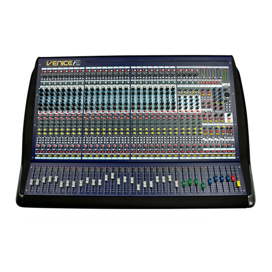
Chapter 1: Introduction Thank you for choosing a Midas VeniceF mixing console. The VeniceF range of consoles have been developed to meet the needs of demanding live sound engineers and provide the solution for any audio mixing application in live sound or studio environments. The VeniceF meets the quality of build and performance that you would expect from a Midas console. - Page 10 Chapter 1: Introduction flexible bus structure that lets the engineer configure the console for different applications. The VeniceF consoles (F16 left, F24 top and F32 bottom) All variants include four stereo input channels for use on stereo sources. These share single control knobs and have slightly different functionality as compared to the mono channels.
-
Page 11: Key Features
Key features Item Mono master output XLRM XLRM XLRM FireWire (IEEE 1394) 16-channel, 24-channel, 32-channel, FW400, 6-pin FW400, 6-pin FW400, 6-pin The FireWire interface can be used with any personal computer (PC) fitted with an IEEE1394 port, and is effectively a digital multi-channel cable (up to 2 x 32-channels) for connecting the PC to the console. -
Page 12: Control Surface
Chapter 1: Introduction • Mains power supply — universal power supply unit (PSU) with mains input socket and on/off switch. • Lamps — socket(s) for fitting lamps. • Playback/record I/Os — input/output sockets for playback and recording. • Warranty — standard Midas 3-year warranty. Control surface The surface of the VeniceF can be divided into the following main vertical sections. -
Page 13: Rear Panel
Rear panel Rear panel The VeniceF has a rear panel that houses the following. Rear panels of the VeniceF consoles showing the main areas Item Description See “Master outputs (mono and stereo)” on page 66. See “Stereo returns” on page 63, “Groups” on page 57, “Matrices” on page 61, “Monitors”... -
Page 14: External Connections
Chapter 1: Introduction Rear panel of the VeniceF16 showing the main connector sections Inserts and returns. Mono input channel (insert, direct out, line in and mic in). Dual stereo channel (line in left and right, and mic inputs left and right). Playback I/Os (left and right). -
Page 15: Signal Flow
Signal flow Connection(s) Description Notes All primary outputs Balanced XLR connectors, Master channels 50R source Aux, group, matrix, monitor and local (monitor) buses Talk mic in talk mic section of outputs (control surface) All secondary outputs Balanced Jack connectors, Mono channels (direct outs) 50R source Headphone outputs... - Page 16 Chapter 1: Introduction The following table shows the signal flow in detail. Signal Sourced from Routed to Mono Balanced XLR mic/line Buses, insert Jack, direct input or balanced Jack line output Jack and FireWire Z input (common gain connection control with above) or FireWire connection or insert return Stereo...
-
Page 17: Mix Matrix
Mix matrix Mix matrix Ultimately, the mix matrix defines the capability of each VeniceF. It follows the console layout, where inputs run vertically and buses run horizontally. A mix matrix is usually defined as the number of buses and the quantity of simultaneously-mixable inputs there are per bus. -
Page 18: Service And Support
Chapter 1: Introduction • Unless otherwise stated, an illuminated LED means that its related control/function is on and when extinguished it is off. • Although this manual is based on the VeniceF32 (pictures shown throughout), the information also applies to the F16 and F24 models unless stated otherwise. Trademarks FireWire and the FireWire symbol are trademarks of Apple Inc., registered in the U.S. -
Page 19: Chapter 2: Getting Started
Chapter 2: Getting Started This chapter shows you how to prepare the VeniceF for operation, which includes: • Installation • Connecting up • Setting up • Powering up Before installing, setting up or operating this equipment make sure you have read and fully understand all of the “IMPORTANT SAFETY INSTRUCTIONS”... -
Page 20: Radio Frequency Interference
Chapter 2: Getting Started Radio frequency interference This equipment has been tested and found to comply with the limits for a Class A digital device, pursuant to Part 15 of the FCC Rules. These limits are designed to provide reasonable protection against harmful interference when the equipment is operated in a commercial environment. -
Page 21: Connecting Up
Connecting up Connecting up To ensure the correct and reliable operation of your equipment, only high quality, balanced, screened, twisted pair audio cable should be used. XLR connector shells should be of metal construction so that they provide a screen when connected to the console and, where appropriate, they should have Pin 1 connected to the cable screen. -
Page 22: Connecting To Balanced/Unbalanced Equipment
Chapter 2: Getting Started Connecting to balanced/unbalanced equipment The inserts of the VeniceF are unbalanced. Ideally, you will be connecting the inserts to balanced equipment to help avoid noise problems due to grounding. Input and output sockets on rear of external device Male XLR Send... -
Page 23: Other Connections
Connecting up Other connections The section gives details of the other VeniceF interconnections. Description Example Pinouts Example of socket 4-pin, male XLR 1 = N/A chassis connector(s) 2 = N/A on the rear panel for 3 = ground connecting 12V/5W 4 = 12V lamp(s) 1-off socket in the... -
Page 24: Setting Up
Chapter 2: Getting Started Setting up There is no initial setting up required for the VeniceF console. However, if you want to use FireWire, you will need to set up you PC first (see Chapter 3 "Using The VeniceF With FireWire" on page 17). Switching the VeniceF on/off Switch the VeniceF on/off via the mains switch on the rear panel. -
Page 25: Chapter 3: Using The Venicef With Firewire
Chapter 3: Using The VeniceF With FireWire This chapter shows you how to prepare your PC/Mac for using FireWire, how to update the FireWire driver and how to troubleshoot FireWire. For information on how to use FireWire with the ‘bundled’ recording software, refer to the Software Application Guide. Installing FireWire on a PC This section shows how to install and set up FireWire on a PC running the Windows®... - Page 26 Chapter 3: Using The VeniceF With FireWire In the Select Destination Location window, click Next. You can change the install location by typing it in or using the browse facility. In the Select Additional Tasks window, click Next. You can choose to create a desktop icon by selecting the Create a desktop icon option.
- Page 27 Installing FireWire on a PC If the Windows “Logo testing” compatibility window appears, click Continue Anyway. To complete the installation, select the Yes, restart the computer now option and then click Finish. You must restart your PC before using the VeniceF driver you have just installed.
-
Page 28: Step B - Connecting The Venicef To Your Pc
Chapter 3: Using The VeniceF With FireWire Step B — Connecting the VeniceF to your PC Important: The VeniceF must be switched on before the FireWire cable is connected to it. When you use your PC with the VeniceF for the first time after installing the FireWire device driver, you will need to install the VeniceF device software. - Page 29 Installing FireWire on a PC For standard installation, select the Install the software automatically (Recommended) option and then click Next. The wizard will perform a search for the correct driver. When it has finished, click Next. When the Windows “Logo testing” compatibility window appears, click Continue Anyway.
-
Page 30: Step C - Configuring The Firewire Settings For The Venicef
Chapter 3: Using The VeniceF With FireWire After the wizard has finished installing the driver, click Finish. After the device hardware has been successfully installed, you will see a Found New Hardware balloon on your desktop. You are now ready to configure the VeniceF FireWire settings (see Step C below). Step C —... - Page 31 Installing FireWire on a PC >> To change the FireWire settings Use the drop-down lists and buttons on the Midas FW settings screen to change the FireWire settings, as desired, using the following diagram and the accompanying list of associated elements to guide you. Note: The settings available for configuration may be dependent on a number of variables, such as the hardware specification of the PC, the type of operating system you are using, the recording software application, etc.
- Page 32 Chapter 3: Using The VeniceF With FireWire Item Element Description Buffer Size This drop-down list lets you select the buffer size that drop-down list the PC/Mac will use for the recording software. Select buffer size according to your equipment, remembering that if it is too small you will suffer audio clicks and pops, and if it is too large there will be audible delays (latency).
-
Page 33: Installing Firewire On A Mac
Installing FireWire on a Mac Installing FireWire on a Mac This section shows how to install and set up FireWire on a Mac. This procedure comprises the following main steps: • “Step A — Installing the device driver on your Mac” •... - Page 34 Chapter 3: Using The VeniceF With FireWire At the Introduction stage of the installation procedure, observe the driver release notes and then click Continue. If your Mac has another hard drive connected, the Destination Select stage will let you select another install location.
-
Page 35: Step B - Connecting The Venicef To Your Mac
Updating the FireWire driver Step B — Connecting the VeniceF to your Mac Important: The VeniceF must be switched on before the FireWire cable is connected to it. >> To connect the Mac to the console Do not attempt the following procedure until you have completed Step A (see “Step A —... -
Page 36: Troubleshooting Firewire
Chapter 3: Using The VeniceF With FireWire Troubleshooting FireWire The following subsections may help you overcome any problems that may arise when using FireWire. Audio problems If you encounter any problems with the audio, for example, when recording, try changing the FireWire settings (see “Step C — Configuring the FireWire settings for the VeniceF”... -
Page 37: Chapter 4: Working With The Console
Chapter 4: Working With The Console The following chapters give a description of the controls on the console surface and include useful operating information. • Chapter 5 "Mono Input Channel" on page 31 • Chapter 6 "Dual Stereo Input Channel" on page 43 •... - Page 38 Chapter 4: Working With The Console VeniceF Operator Manual...
-
Page 39: Chapter 5: Mono Input Channel
Chapter 5: Mono Input Channel This chapter details the mono input channels (8/16/24) of the VeniceF. It describes the sections of each channel on the control surface and the related connectors on the rear panel. Mono input channels on the control surface (F32 shown) Although the actual number of mono input channels on your VeniceF will depend upon your choice of frame, their function remains the same. -
Page 40: Overview Of The Mono Input Channel
Chapter 5: Mono Input Channel Overview of the mono input channel Each mono channel has an XLR input that can be used for mic or line level signals up to +32dBu. An additional 1/4” inch TRS Jack socket, provides an input for line level signals that require protection against accidental 48-volt connection. -
Page 41: Rear Panel
Rear panel Rear panel The VeniceF channel inputs are located on the rear panel of the console and each channel comprises the following. Mono input channel connectors Item Description insert connector Insert point on a single 1/4” TRS Jack socket. This is unbalanced and requires a conventionally-wired insert lead. -
Page 42: Gain
Chapter 5: Mono Input Channel Gain This section lets you adjust the level of the mic input signal, switch on 48 volts phantom power for the mic, attenuate the input signal by 20dB, invert the mic polarity and enable the high pass filter on the mic input. Mic gain section of the mono input channels Item Description... -
Page 43: Firewire
FireWire FireWire This section lets you select the channel input source as mic/line (analogue) or FireWire (digital) and select the FireWire output signal as pre-EQ or post-EQ. For more information on FireWire, see Chapter 3 "Using The VeniceF With FireWire" on page 17. FireWire section of the mono input channels Item Description... - Page 44 Chapter 5: Mono Input Channel Each mono input channel of the VeniceF has a four-band, swept EQ, allowing tonal control over the input signal. EQ section of the mono input channels Item Description Treble gain/freq control knob This dual-concentric control knob adjusts the gain/frequency of the treble EQ: •...
-
Page 45: Monitors
Monitors Item Description Lo mid gain/freq control knob This dual-concentric control knob adjusts the gain/frequency of the lo mid EQ: • gain The top control knob adjusts the gain of the lo mid band, which is continuously variable from -15dB to +15dB with a centre detent of 0dB. •... -
Page 46: Auxes
Chapter 5: Mono Input Channel Auxes The VeniceF has four aux sends per input channel, which can be used for effects sends, monitors or as extra assignable outputs from the console. Each aux has a control knob that gives continuous adjustment of the level sent from the input channel to the aux buses, in the range (infinity/off) to +6dB. -
Page 47: Pan, Routing, Mute And Solo
Pan, routing, mute and solo Pan, routing, mute and solo The VeniceF is a flexible mixing console with four group buses plus stereo and mono. Groups and solo sections of the mono input channels Item Description Group switches Each group switch routes the channel signal to its associated group bus (as described later in this section). - Page 48 Chapter 5: Mono Input Channel Group routing, which is post-EQ, post-mute and post-fader, can be configured in either of two modes: • Pre-pan (mono) Each group is sent the same mono signal, so that, for example, selecting 1, 2 and 3 will send to each group equally. •...
-
Page 49: Fader And Meter
Fader and meter Fader and meter The VeniceF has a 100 mm fader and a four-LED signal meter per mono input channel. Fader section of the mono input channels Item Description LED meter These four LEDs comprise the input channel meter, which lets you monitor the input signal without having to use the PFL. - Page 50 Chapter 5: Mono Input Channel VeniceF Operator Manual...
-
Page 51: Chapter 6: Dual Stereo Input Channel
Chapter 6: Dual Stereo Input Channel This chapter details the dual stereo input channels of the VeniceF. It describes the sections of each dual stereo channel on the control surface and the related connectors on the rear panel. Dual stereo input channels on the control surface All types of VeniceF have four pairs of dual stereo input channels. -
Page 52: Overview Of The Dual Stereo Input Channel
Chapter 6: Dual Stereo Input Channel Overview of the dual stereo input channel The VeniceF dual stereo channel (shown right) is equipped with two XLR inputs, which are used for mic/line level signals up to +32dBu. Two 1/4” TRS Jack sockets provide inputs for line level signals that require protection against accidental 48-volt connection. -
Page 53: Rear Panel
Rear panel Rear panel The VeniceF channel inputs are located on the rear panel of the console. Dual stereo input channel connectors Item Description line in left Line in on a single, balanced 1/4” TRS Jack socket. line in right Line in on a single, balanced 1/4”... -
Page 54: Gain (Stereo Mic Inputs)
Chapter 6: Dual Stereo Input Channel Gain (stereo mic inputs) This section has the same functionality as the gain section of the mono input channels except for the following. For full details, see “Gain” on page 34. • 20dB pad switch On dual stereo input channels the pad switch has no effect upon the left and right line levels. -
Page 55: Stereo Line Inputs
Stereo line inputs Stereo line inputs This section lets you adjust the level of the stereo line input signal, solo the signal and route it to the channel or directly to masters. Stereo line input section of the dual stereo input channels Item Description stereo line gain control knob... - Page 56 Chapter 6: Dual Stereo Input Channel Each dual stereo input channel of the VeniceF has a four-band, fixed EQ (treble and bass shelving EQ and hi and lo mid EQ stages), allowing tonal control over the input signal. EQ section of the dual stereo input channels Item Description Treble control knob The treble shelving EQ gain is continuously variable...
-
Page 57: Monitors
Monitors Monitors The monitor sends of the dual stereo input channels have similar functionality to those of the mono input channels. For more information, see “Monitors” on page 37. Note: Stereo left and right channel signals are summed into a mono signal to be routed to the monitor buses by the channel monitor sends. -
Page 58: Pan, Routing, Mute And Solo
Chapter 6: Dual Stereo Input Channel Pan, routing, mute and solo The VeniceF is a flexible mixing console with four group buses plus stereo and mono. Group and solo sections of the dual stereo input channels Item Description Group switches Each of these four group switches routes its channel signal to its associated group bus (see “Group sends”... -
Page 59: Group Sends
Pan, routing, mute and solo Group sends Group sends are post-EQ, post-mute and post-fader. The group sends can be configured in either of two modes using the mono sum switch: • mono sum switch out (stereo) Each pair of groups behave as if they were stereo groups. -
Page 60: Fader And Meter
Chapter 6: Dual Stereo Input Channel Fader and meter The VeniceF fader section has the following functions. Fader section of the dual stereo input channels Item Description LED meter These LEDs comprise the dual stereo input channel meter, which lets you monitor the input signal without having to use the PFL. The meter will display the higher of the two signals (left or right). -
Page 61: Chapter 7: Output Section
Chapter 7: Output Section This chapter deals with the output section of the VeniceF. It describes the control surface and the related connectors on the rear panel. Output section of the control surface The output section comprises the following main areas: •... -
Page 62: Rear Panel
Chapter 7: Output Section Rear panel The main outputs of the VeniceF are located on the rear of the console. Output connections on rear panel VeniceF Operator Manual... -
Page 63: Overview Of The Outputs Section
Overview of the outputs section Overview of the outputs section The outputs section comprises the following main areas. Item Description See “Groups” on page 57. See “FireWire” on page 58. See “Stereo returns” on page 63. See “Matrices” on page 61. See “Monitors”... -
Page 64: Output Module Notes
Chapter 7: Output Section Output module notes Before looking at the function of the output section of the console, it is essential that you are comfortable with a few of the console’s features that affect groups, matrices and auxes. Rather than discuss these features in each section (although they will be repeated there), an understanding of their function in a more general context is desirable. -
Page 65: Groups
Groups Groups Each of the four group buses has an output and an insert. Group connectors on rear panel Item Description Group insert sockets Each group has an insert point via a single 1/4” TRS Jack socket. Group output sockets Each group has an output via a male XLR chassis connector. -
Page 66: Firewire
Chapter 7: Output Section Item Description Meter LEDs These LEDs comprise the group meter, which monitors the signal level of the group bus. Range is from -12dBu to +18dBu (3dBu steps from -12dBu to 0dBu, and 6dBu steps from 0dBu to +18dBu). aux c/o switch See “Group-aux changeover”... - Page 67 FireWire firewire output select section on the control surface When an orange FireWire button is switched on (depending on button precedence), it replaces the FireWire output of its respective stereo input channel for its associated buses. The orange LEDs above illuminate to indicate which pair of buses are overriding which stereo channel FireWire output.
- Page 68 Chapter 7: Output Section The hierarchy of the three pairs of FireWire override buttons can be summarised by the following: • The right button of the pair overrides any FireWire output. • The left button of the pair only overrides the stereo input channel FireWire output (default).
-
Page 69: Matrices
Matrices Matrices There is an output connector and insert connector on the rear panel for both matrix outputs. Two matrix inserts and two matrix outputs on the rear panel FireWire output is available for the matrix outputs by overriding the relevant dual stereo input channel 29-30. - Page 70 Chapter 7: Output Section Item Description group 1 to group 4 control knobs Each of the groups (1-4) has its own individual matrix send level, which is continuously variable from (infinity/ off) to +6dB. Unity (0dB) is also marked on the scale, allowing the signal to be routed to the matrix without any attenuation or gain.
-
Page 71: Stereo Returns
Stereo returns Stereo returns There are two stereo returns that route to masters, certain groups and the two monitor buses. Stereo returns 1 and 2 on the rear panel. Each return has left and right TRS 1/4” TRS Jack sockets. The stereo returns section is immediately below the firewire output select section. -
Page 72: Monitors
Chapter 7: Output Section Monitors There is an output connector and insert connector on the rear panel for both monitor bus outputs. Two monitor inserts and two monitor outputs on rear panel FireWire output is available for the monitors by the overriding the relevant dual stereo input channel. -
Page 73: Auxes
Auxes Item Description MUTE switch and red LED The MUTE switch mutes the monitor send output signal. The mute LED illuminates to show that the mute is on. SOLO switch and yellow LED The SOLO switch routes the monitor send signal to the mono PFL bus and stereo AFL buses. -
Page 74: Master Outputs (Mono And Stereo)
Chapter 7: Output Section Item Description pre switch This is the aux global control bus master pre-fader switch, which determines whether the aux contribution from the input channel is pre-fader or post-fader. aux c/o switch See “Group-aux changeover” on page 56 Pre-fade aux 1-4 sends are sourced after the channel insert, mute and EQ, but before the channel fader. - Page 75 Master outputs (mono and stereo) FireWire output is available for the left and right master channels by the overriding the relevant dual stereo input channel. There is no FireWire output for the mono channel. For more information, see “FireWire” on page 58. The controls shown in this section are directly responsible for the main outputs from the console.
-
Page 76: Signal Generator And Talkback
Chapter 7: Output Section Item Description solo LED This yellow LED illuminates to show when the meters in the master meters section are functioning as solo meters. The solo bus levels (afl L, afl R and pfl) are shown on the solo meters. The solo meters are pre- monitor or phones output mute and level, and are unaffected by changes in the headphone level or the level sent to the local monitor outputs. -
Page 77: Playback And Recording
Playback and recording Item Description matrix switch This is a routing button that routes the talk bus/signal generator signal to both matrix buses. aux switch This is a routing button that routes the talk bus/signal generator signal to all aux buses. gain control knob Adjusts the gain of the talk mic, which is continuously variable from +10dB to +60dB. -
Page 78: Recording
Chapter 7: Output Section Item Description MUTE switch and red LED The MUTE switch mutes the input signal. The LED illuminates to show when the mute is on. SOLO switch and yellow LED The SOLO switch routes the input signal to the mono PFL bus and stereo AFL buses. -
Page 79: Lamps
Lamps Item Description Output socket The local monitor section has a 1/4” TRS Jack socket for headphones. There is an additional socket under the armrest of the console. pfl switch and yellow LED When this solo switch is on (LED illuminated), the local monitor and headphones signal is sourced from the PFL mono signal, rather than the AFL stereo default. - Page 80 Chapter 7: Output Section VeniceF Operator Manual...
-
Page 81: Appendix A Functional Block Diagrams
Appendix A: Functional Block Diagrams This chapter contains the VeniceF signal path diagrams. VeniceF Operator Manual... -
Page 82: Overview
Appendix A: Functional Block Diagrams Overview VeniceF Operator Manual... -
Page 83: Mono Input Module
Mono input module Mono input module VeniceF Operator Manual... -
Page 84: Stereo Input Module
Appendix A: Functional Block Diagrams Stereo input module VeniceF Operator Manual... -
Page 85: Stereo Return
Stereo return Stereo return VeniceF Operator Manual... -
Page 86: Group
Appendix A: Functional Block Diagrams Group VeniceF Operator Manual... -
Page 87: Aux
VeniceF Operator Manual... -
Page 88: Monitor
Appendix A: Functional Block Diagrams Monitor VeniceF Operator Manual... -
Page 89: Stereo Master
Stereo master Stereo master VeniceF Operator Manual... -
Page 90: Mono Master
Appendix A: Functional Block Diagrams Mono master VeniceF Operator Manual... -
Page 91: Matrix
Matrix Matrix VeniceF Operator Manual... -
Page 92: Solo And Comms
Appendix A: Functional Block Diagrams Solo and comms VeniceF Operator Manual... -
Page 93: Digital
Digital Digital VeniceF Operator Manual... - Page 94 Appendix A: Functional Block Diagrams VeniceF Operator Manual...
-
Page 95: Appendix B Technical Specification
Appendix B: Technical Specification This appendix provides the full technical specification for the VeniceF series of mixing consoles. Due to a policy of continual improvement, Midas reserves the right to alter the function or specification at any time without notice. Table 3: VeniceF technical specifications Item Details... - Page 96 Appendix B: Technical Specification Item Details Additional features Connector for desk lamps 4-pin, 12V/5W Accessories Dust cover Included Included Included Table 4: VeniceF performance specifications Input impedance 2k balanced Line 10k balanced Input gain Continuously variable from 10dB to 60dB Line mono channel Continuously variable from 0dB to 50dB...
- Page 97 Output impedance All line outputs 50 ohms balanced source Headphones To drive 32 ohms Maximum output level Line outputs (into 600R) +21dBu Headphones (into 50R) +18dBu (750mW) Digital output level Sampling frequency 48kHz or 44.1kHz Dynamic range (20Hz to 105dB 20kHz) Nominal signal level -60dBu to +10dBu...
-
Page 98: Dimensions
Appendix B: Technical Specification Dimensions The following shows the external dimensions of the VeniceF series consoles. Dimensions are in millimetres, with the equivalent in inches enclosed in brackets. (0.6”) 6.5° (approx.) (7.2”) 669 (26.3”) (2.0”) VeniceF Operator Manual... -
Page 99: Appendix C Application Notes
Appendix C: Application Notes This appendix provides application notes as a guide to help you with VeniceF console operation. With its flexible routing and functionality, the VeniceF was designed with real-world sound engineers in mind, working in the real world. So, for engineers that haven’t got a great deal of experience in live sound engineering, the following subsections may provide a few helpful guidelines. -
Page 100: The Effect Of Eq
Appendix C: Application Notes channels will receive the same signal at the same time so, typically, when 16 channels are summed together a gain of around 5dB to 8dB will be seen. It is important to leave some headroom in the summing amplifiers so that they do not overload, should the sum exceed the maximum level. -
Page 101: Unity Gain
Unity Gain Unity Gain Unity gain is a gain of 1, that is, no gain or attenuation is applied to a signal. If a signal entered a mono line level input of the VeniceF at 0dBu and the gain was set to +10dB (an internal 10dB attenuation sets the net gain to 0dB), then the signal was routed to each output at 0dB, the channel fader was set to 0dB and each output fader was set to 0dB, the output should be 0dBu (or unity). -
Page 102: Routing
Appendix C: Application Notes There are a number of solutions to this problem: • Reduce the amplifier’s input attenuators to a level where the amplifier and console clip at the same point. For example, the input sensitivity is 0dBu, setting the input attenuator on the amplifier to -21dB would mean that the console would clip at the same time as the amplifier. -
Page 103: Mon Mode
Routing The submix is now set up. The group level can be used to control the overall level of the channels (retaining their relative levels), mute the submix output or solo the submix signal. Note: Muting the submix is not the same as muting the channels. Aux sends and other group sends will remain active. - Page 104 Appendix C: Application Notes VeniceF Operator Manual...
-
Page 105: Appendix D Crib Sheets
Appendix D: Crib Sheets This appendix provides you with a template each for the mono and dual stereo input channels. These will help you keep a record of your most important settings and make notes. If necessary, you can make copies of these pages if you need more records. VeniceF Operator Manual... -
Page 106: Mono Input Channels
Appendix D: Crib Sheets Mono input channels Notes: VeniceF Operator Manual... -
Page 107: Dual Stereo Input Channels
Dual stereo input channels Dual stereo input channels Notes: VeniceF Operator Manual... - Page 108 Appendix D: Crib Sheets VeniceF Operator Manual...
-
Page 109: Appendix E Best Grounding Practice
Appendix E: Best Grounding Practice This appendix gives details of the best grounding practices for the VeniceF console in order to get the optimum performance out of it. Safety first The VeniceF is classified as a class 1 device and as such there is a safety requirement for the power cable to provide an earth connection to the console. -
Page 110: Noise Sources
Appendix E: Best Grounding Practice Audio connection Loop currents GEQ (for example, Square Midas VeniceF ONE Graphic) console Power connection Power connection Power distribution unit (PDU) Ground loop Noise sources Audio manufacturers have known about these issues for many years and most equipment is designed to reduce ground loop generation to the bare minimum or to minimise the effects. - Page 111 Noise sources Laptop PC/Mac FireWire connection Broken ground Isolation loop barrier Midas VeniceF console Power supply unit (PSU) with internal isolation Power connection Power connection Power distribution unit (PDU) Isolated FireWire computer system. Note how the isolation barrier breaks the ground loop.
-
Page 112: Noise Solutions
Appendix E: Best Grounding Practice Noise solutions The grounding on the VeniceF is very robust and often such ground loop induced noises are negligible, but to get the very best out of your console, and especially out of any less robust equipment within the overall system, some consideration should be given to good grounding practice as follows: •... -
Page 113: Balanced Connections
Balanced connections Audio connection GEQ (for example, Square Midas VeniceF ONE Graphic) Small loop area console Power connection Power connection Power distribution unit (PDU) Loop area diagram showing a small loop area Balanced connections Balanced connections are generally immune to ground loops because the grounded screen conductor is not used as a reference for the signal conductors. -
Page 114: Balanced Transformers
Appendix E: Best Grounding Practice Balanced transformers Active electronic circuits achieve good results, but for ultimate noise rejection, transformers are needed. Transformers colour the sound especially at low and high frequencies due to core saturation and impedance rises. They are also expensive, so they are typically only used as external problem solvers when all else fails. -
Page 115: Ground Referenced Connections
Ground referenced connections Source Destination Screen Chassis Chassis Screen termination diagram showing screen broken at source Ground referenced connections Many unbalanced signals are passed between pieces of equipment where one of the devices is balanced and the other is not. By careful wiring using two-core cable with an overall screen, it is possible to convert this connection so that it operates in a similar way to a balanced system, with a ground reference that is not corrupted by ground loop currents in the shield. -
Page 116: Unbalanced Connections
Appendix E: Best Grounding Practice connecting balanced external processing equipment to the insert points, the connection method described in this section should be adopted so as to benefit from the CMR of the external unit. For an example of how to wire a ground referenced insert, see Figure 2 on page 14. Unbalanced connections Ground loops with unbalanced signals are more difficult to deal with, but there are several good techniques available. -
Page 117: Xlr Shells
XLR shells XLR shells XLR pin 1s should only be used to provide a ground connection for cable screens. The shell (body) of cable XLRs also need to be connected to ground so they provide a screen for the terminals, but they should not be wired internally to the pin 1 terminal. Their ground should be prevented from contact with the panel XLR connector body. - Page 118 Appendix E: Best Grounding Practice Laptop PC/Mac FireWire connection Audio connection Bond 19” rack Midas VeniceF console Power supply unit (PSU) without internal Power connection isolation barrier Power connection Power connection Power connection Power distribution unit (PDU) Diagram showing the bond connection between console and 19” rack VeniceF Operator Manual...
-
Page 119: Appendix F Service Information
Appendix F: Service Information This appendix give details of how to look after your VeniceF. Routine maintenance To help keep your VeniceF unit in good working order and to make sure it gives you optimum performance, we recommend that you carry out the following about once every month. -
Page 120: Equipment Disposal
Appendix F: Service Information Equipment disposal When this equipment has come to the end of it useful life, its disposal may come under the DIRECTIVE 2002/96/EC OF THE EUROPEAN PARLIAMENT AND OF THE COUNCIL of 27 January 2003 on waste electrical and electronic equipment (WEEE). Hazardous substances in WEEE contaminate water, soil and air and ultimately put at risk our environment and health. - Page 121 Thank you for reading through this Operator Manual. We hope you found it useful. Please feel free to send us your comments. Our contact details and website address can be found at the front of this document.
- Page 122 Midas Klark Teknik Ltd. Klark Industrial Park, Walter Nash Road, Kidderminster. Worcestershire. DY11 7HJ. England. Tel: +44 1562 741515, Fax: +44 1562 745371 Email: info@midasklarkteknik.com Website: www.midasconsoles.com...