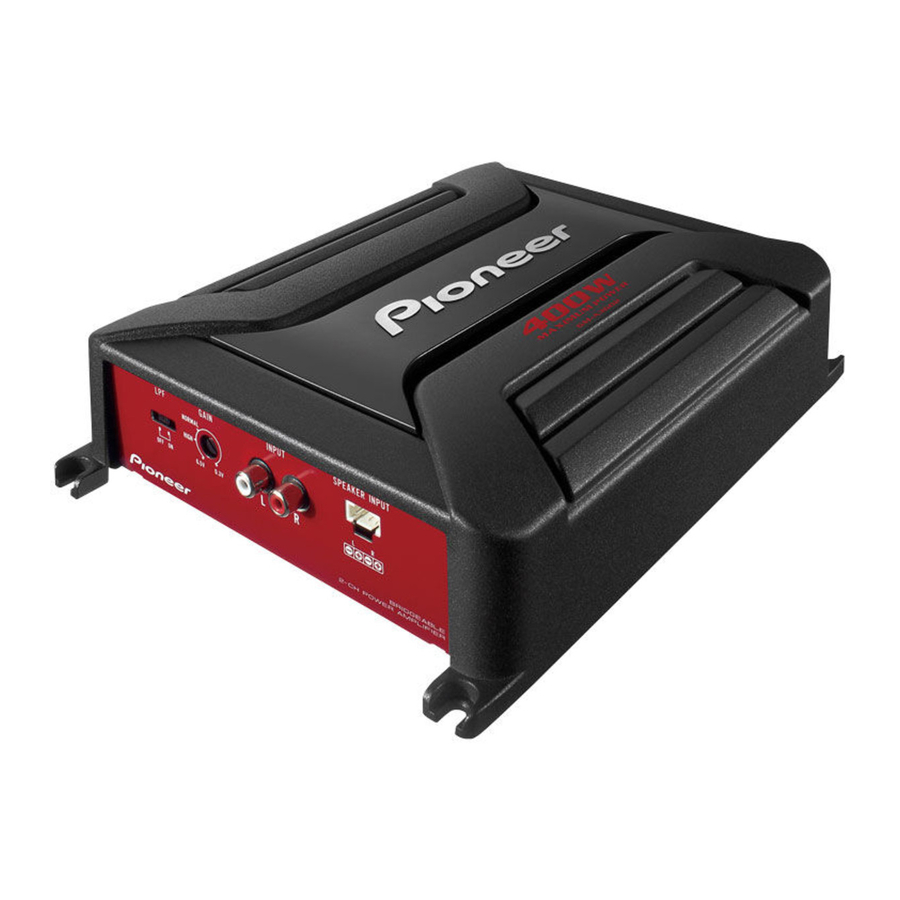
Pioneer GM-A5602 Owner's Manual
Bridgeable two-channel power amplifier
Hide thumbs
Also See for GM-A5602:
- Owner's manual (92 pages) ,
- Owner's manual (11 pages) ,
- Owner's manual (49 pages)

Related Manuals for Pioneer GM-A5602


Summary of Contents for Pioneer GM-A5602
- Page 1 BRIDGEABLE TWO-CHANNEL POWER AMPLIFIER AMPLIFICATEUR DE PUISSANCE PONTABLE À DEUX CANAUX AMPLIFICADOR DE POTENCIA DE DOS CANALES PUENTEABLE...
-
Page 2: Before You Start
Before you start Thank you for purchasing this PIONEER - Reorient or relocate the receiving antenna. product - Increase the separation between the equipment and receiver. - Connect the equipment into an outlet on a cir- To ensure proper use, please read through this cuit different from that to which the receiver is manual before using this product. -
Page 3: If You Experience Problems
! Do not turn up the volume so high that you please contact your dealer or nearest author- can t hear what s around you. ized Pioneer Service Station. ! Use caution or temporarily discontinue use in potentially hazardous situations. - Page 4 Before you start ! Check the connections of the power supply ing functions will operate to protect the product and speakers if the fuse of the separately sold and speaker output. ! The power indicator will turn off and the am- battery wire or the amplifier fuse blows.
-
Page 5: Setting Gain Properly
(standard output of 500 mV), set to the NORMAL position. For use with an RCA GM-A3602 equipped Pioneer car stereo, with maxi- Front side mum output of 4 V or more, adjust level to match that of the car stereo output. - Page 6 ! Despite correct volume and gain settings, the unit sound still cuts out periodically. In such cases, please contact the nearest authorized Pioneer Service Station. Gain control of this unit Preout level: 2 V (Standard: 500 mV)
-
Page 7: Connecting The Units
Please see the following section for speaker connection instructions. Refer to Connections when using the speaker input wire on page 9. Fuse 30 A × 2 (GM-A5602) / 25 A × 1 (GM- A3602) Fuse (30 A) × 2 Grommet... -
Page 8: About Bridged Mode
Speaker channel Power na, antenna cable and tuner. Nominal input: Two-channel output Min. 150 W (GM-A5602) Min. 60 W (GM-A3602) About bridged mode Nominal input: One-channel output Min. 450 W (GM-A5602) Min. -
Page 9: One-Channel Output
Connecting the units One-channel output work with some headunits. In such cases, please use a system remote control wire (sold sepa- rately). If multiple amplifiers are to be connected together synchronously, connect the head unit and all amplifiers via the system remote control wire. -
Page 10: Connecting The Speaker Output Terminals
Connecting the units Insert the O-ring rubber grommet into the Power terminal vehicle body. Terminal screws Drill a 14 mm (1/2 in.) hole into the vehicle Battery wire body. Ground wire System remote control wire Twist the battery wire, ground wire and system remote control wire. - Page 11 Connecting the units Terminal screws Speaker wires Speaker output terminals...
-
Page 12: Before Installing The Amplifier
! Place all cables away from hot places, such Hole-to-hole distance: 338 mm (13-1/4 in.) as near the heater outlet. (GM-A5602) / 228 mm (9 in.) (GM-A3602) ! The optimal installation location differs de- Hole-to-hole distance: 196 mm (7-3/4 in.) pending on the car model. -
Page 13: Additional Information
Specifications Power output ......150 W RMS × 2 Channels (at 14.4 V, 4 W and ≦ 1 % GM-A5602 THD+N) S/N ratio ........75 dBA (reference: 1 W into Power source ......14.4 V DC (10.8 V to 15.1 V... - Page 14 Additional information CEA2006 Specifications Power output ......60 W RMS × 2 Channels (at 14.4 V, 4 W and ≦ 1 % THD S/N ratio ........78 dBA (reference: 1 W into 4 W) Notes ! Specifications and the design are subject to modifications without notice.
- Page 15 TEL: 1-877-283-5901 TEL: 905-479-4411 Blvd.Manuel Avila Camacho 138 10 piso Col.Lomas de Chapultepec, Mexico, D.F. 11000 TEL: 55-9178-4270 先鋒股份有限公司 台北市內湖區瑞光路407號8樓 ã 2013 PIONEER CORPORATION. 電話: 886-(0)2-2657-3588 All rights reserved. 先鋒電子(香港)有限公司 ã 2013 PIONEER CORPORATION. 香港九龍長沙灣道909號5樓 Tous droits de reproduction et de 電話:...
- Page 16 GARANTIE Pioneer Electronics (USA) Inc. (PUSA) et Pioneer Electronique du Canada, Inc. (POC) garantissent que les produits distribues par PUSAaux Etats-Unis et par POC au Canada qui, apres a voir ete installes et utilises conformement au manuel de l'utilisateur inclus avec I' unite, ne fonctionnent pas de fa9on appropriee dans des conditions d'utilisation normales en raison d'un vice de fabrication, seront repares ou remplaces par une unite de valeur comparable, au choix de PUSAou de POC, sans que vous deviez payer pour les pieces ou les travaux de reparation.
- Page 17 Within 40 days of receiving your complaint, Pioneer will investigate the dispute and will either: (1) respond to your complaint in writing informing you what action Pioneer will take, and in what time period, to resolve the dispute; or (2) respond to your complaint in writing informing you why it will not take any action.