IBM 4820 Planning, Installation And Service Manual
4820 surepoint solution touch screen monitors
Hide thumbs
Also See for 4820:
- System reference manual (124 pages) ,
- Planning, installation and service manual (126 pages)

Related Manuals for IBM 4820


Summary of Contents for IBM 4820
- Page 1 4820 SurePoint Solution Planning, Installation and Service Guide January 14, 2005 GA27-4231-06...
- Page 3 4820 SurePoint Solution Planning, Installation and Service Guide January 14, 2005 GA27-4231-06...
- Page 4 Appendix C, “Notices.” Seventh Edition (February 2004) This edition applies to the IBM 4820 SurePoint Solution and to all subsequent releases and modifications until otherwise indicated in new editions. This publication is available on the IBM Retail Stores solutions electronic Support Web site.
-
Page 5: Table Of Contents
. 1-9 Interference (VCCI) statement . . C-3 Korean Communications Statement . . C-4 Chapter 2. Installing the IBM 4820 . . . 2-1 Taiwanese class A warning statement . . C-4 Tailoring your installation . . 2-1 Electrostatic discharge (ESD) . -
Page 6: January
January 14, 2005 4820 Planning, Installation and Service Guide... -
Page 7: Figures
January 14, 2005 Figures 1-1. 4820 SurePoint Solution with features and 2-24. Inserting the stiffening plate . . 2-20 available pedestals . . 1-2 2-25. Securing the arm assembly to the 4694 2-21 1-2. Pedestal types . . 1-4 2-26. - Page 8 January 14, 2005 4820 Planning, Installation and Service Guide...
-
Page 9: Tables
January 14, 2005 Tables 1-1. 4820 SurePoint Solution models and features 1-1 2-2. Connector icons . . 2-7 1-2. 4820 SurePoint Solution hardware options 2-3. Summary of touch response modes 2-43 1-3. Supported operating systems . . 1-5 4-1. Touch screen status messages . - Page 10 January 14, 2005 viii 4820 Planning, Installation and Service Guide...
-
Page 11: About This Guide
4820 SurePoint Solution. v Chapter 2, “Installing the IBM 4820,” on page 2-1 provides the installation steps for the display and the features. v Chapter 3, “Maintaining the IBM 4820,” on page 3-1 describes common maintenance procedures for all models of the 4820. -
Page 12: Tell Us What You Think
January 14, 2005 Driver and service diskette information Under SurePOS Peripherals, click IBM SurePoint Solution to go to the IBM 4820 SurePoint System Support page, where you can download the following software: v 4694/4695/ISA Service/Diagnostic Diskette, Version 5.33 or later... -
Page 13: Accessibility
To assist users with color-vision deficiencies, the power LED blinks as well as changes color when in low-power mode. v Displays are driven at 60 Hz to eliminate problems caused by screen flicker. © Copyright IBM Corp. 1999, 2004... - Page 14 January 14, 2005 4820 Planning, Installation and Service Guide...
-
Page 15: Summary Of Changes
This edition adds information about the features of Models 4WT and 4GT of the 4820 SurePoint Solution. July 2002 This edition adds information about Models 10D and 1FR of the 4820 SurePoint Solution. January 2002 This edition adds information about the integrated touch pedestal available for the 4694 Point of Sale terminal. - Page 16 January 14, 2005 4820 Planning, Installation and Service Guide...
-
Page 17: Chapter 1. Introducing The Ibm 4820 Surepoint Solution
January 14, 2005 Chapter 1. Introducing the IBM 4820 SurePoint Solution The IBM 4820 SurePoint Solution (see Figure 1-1 on page 1-2) is a family of displays optimized for retail point of sale applications. Choices in touch technology, screen size, I/O device support, and connectivity enable a SurePoint solution for any POS environment. - Page 18 January 14, 2005 Audio kit 4820 Magnetic stripe reader (MSR) Pointing device Distributed Keypad pedestal Integrated pedestal Free-standing pedestal Integrated pedestal Figure 1-1. 4820 SurePoint Solution with features and available pedestals 4820 Planning, Installation and Service Guide...
-
Page 19: Hardware Options
– Short: 255 mm (10 in.) – Tall: 380 mm (15 in.) v Distributed pedestal – Short: 240 mm(9.38 in.) – Tall: 352 mm (13.80 in.) v Free-standing pedestal v VESA bracket (excluding models 2xx and 5xx) Chapter 1. Introducing the IBM 4820 SurePoint Solution... -
Page 20: Pedestal Options
January 14, 2005 Pedestal options The pedestal options for the 4820 SurePoint Solution are integrated, free-standing, or distributed pedestal. See Figure 1-2. Integrated Free standing Distributed Figure 1-2. Pedestal types 4820 Planning, Installation and Service Guide... -
Page 21: Supported Operating Systems
4820-4GT 4820 Resistive Touch Screen Monitors 4820-4FT " 4820-46R U JavaPOS Version 2, Release 2 4820 Non-touch Screen Monitors 4820-42D 4820-4FD 4820-46D U JavaPOS " 4820-48D Version 2, Release 3 4820-10D 4820-1FR Chapter 1. Introducing the IBM 4820 SurePoint Solution... -
Page 22: Views Of The 4820 Surepoint Solution
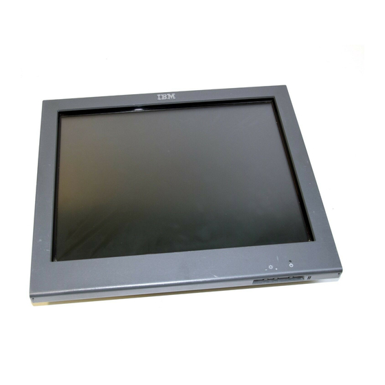
This section shows examples of the various models of the 4820 SurePoint Solution. 12.1-inch and 15.0- inch models Figure 1-3 is a front view of the 12.1-inch and 15.0 inch models of the 4820 SurePoint Solution. Note the location of the control buttons. -
Page 23: Rear View Of 4820
January 14, 2005 Keypad/MSR locating Tabs Keypad/MSR connector Mounting bracket cover/ Key lock Audio kit cylinder Keypad/MSR connector cover Figure 1-4. Rear view of 4820. Options shown may not be available on all models. Chapter 1. Introducing the IBM 4820 SurePoint Solution... -
Page 24: System Software, Touch Drivers, And Diagnostics
Figure 1-5 shows the front and rear views of the 10-inch models: Figure 1-5. Views of 10-inch models System software, touch drivers, and diagnostics You can obtain the appropriate software for your 4820 SurePoint Solution from the IBM Retail Store Solutions Web site:www.ibm.com/solutions/retail/store/ (from the store page, click on Support). -
Page 25: Power Usage
15-inch All SurePoint models can be powered from the power supply, which accepts 100- to 240-V ac input. Those 4820 SurePoint models offering the RS-485 and USB communications interface can be powered from the POS terminal. SurePoint models offering the USB communications interface can be powered from the POS terminal with these exceptions: v 15-inch models require a power supply when attached to 4694 POS terminals. - Page 26 January 14, 2005 1-10 4820 Planning, Installation and Service Guide...
-
Page 27: Chapter 2. Installing The Ibm 4820
5. Connect the cables to your system unit. 6. Power on the system and the 4820 display. See to “Powering on” on page 2-34 7. Perform an auto adjust to obtain the optimal image. See “Adjusting the image” on page 2-35. -
Page 28: Identifying The Pedestal Type
4820 SurePoint Solution. Integrated Free standing Distributed Figure 2-1. Pedestal types Identifying the 4820 cables This section identifies the RS-232 cables for the various models of the 4820 SurePoint Solution. Touch with MSR/keypad: Models 2xx and 5xx RS-232 Touch RS-232 (Touch/MSR/keypad) -
Page 29: Infrared Touch With Msr
January 14, 2005 Touch with MSR RS-232 Touch RS-232 (Touch/MSR) RS-232 MSR Host end 4820 end Figure 2-3. Infrared touch with MSR Touch only RS-232 Touch RS-232 (Touch) 4820 end Figure 2-4. Touch only Chapter 2. Installing the IBM 4820... -
Page 30: Connector Cable For Capacitive And Resistive
Figure 2-5. Connector cable for capacitive and resistive touch RS-232 models. The PS/2 pigtail connector allows you to connect a PS/2 keyboard and perform diagnostics. Touch with MSR RS-232 Touch RS-232 (Touch/MSR) RS-232 MSR Host end 4820 end Figure 2-6. 4820-4FT model with MSR attached 4820 Planning, Installation and Service Guide... -
Page 31: Identifying The 4820 I/O Ports
Installing the IBM 4820 January 14, 2005 Identifying the 4820 I/O ports This section identifies the input/output ports of the various 4820 Models. See Figure 2-6 on page 2-4. Note: This section does not show all possible configurations. Models 2xx, 5xx Figure 2-7. -
Page 32: Models 46T, 46R I/O Ports
12 V dc power USB 1.1 (two units for external connections) Video connector USB 2.0 PS/2 keyboard Enable/disable port for audible beeper diagnostics (Models 42T and 4FT) RS-232 connector RS-485 (EIA 485) port connector port 4820 Planning, Installation and Service Guide... -
Page 33: Connector Icons
Installing the IBM 4820 January 14, 2005 Identifying the icons Icons located near the 4820 SurePoint Solution ports also identify the connection type. Table 2-2 lists these icons. Table 2-2. Connector icons Power Video RS-232 Touch/MSR USB USB out Enable audible beeper (Models 4FT, 42T only) -
Page 34: Installing The Pedestal
This section describes how to install the distributed, integrated, integrated touch and free-standing pedestal. Cable routing steps are included. Distributed pedestal Follow these instructions for installing the 4820 SurePoint Solution to the distributed pedestal: Attaching the distributed pedestal to the counter The distributed pedestal is available in short (238.2 mm/9.38 inches) and tall (350.6... -
Page 35: Video Cable Routing Direction
Routing the cables for the distributed pedestal 1. Remove the trough cover from the distributed pedestal. Figure 2-13. Video cable routing direction 2. As shown Figure 2-13, route the video cable down through the distributed pedestal and leave it unconnected. Chapter 2. Installing the IBM 4820... -
Page 36: Using The Velcro Strip
January 14, 2005 Figure 2-14. Using the velcro strip 3. As shown in Figure 2-14, use the velcro strip that is connected to the power cable and attach it to the video cable. 2-10 4820 Planning, Installation and Service Guide... -
Page 37: Routing The Video And Power Cables
6. Reroute the video cable back down through the distributed pedestal. 7. Attach the cable to the appropriate port in the system unit. Note: Do not attach the video and power cables to the 4820 display. 8. Install you optional hardware. See “Installing the options” on page 2-27. -
Page 38: Distributed Pedestal Parts List Shown With
1. Ensure that the pedestal is secure. 2. Mount the 4820 onto the pedestal: a. Place the 4820 display on the distributed pedestal. Make sure that the metal tabs on the mounting bracket slide into the appropriate slots on the back of the 4820 display. -
Page 39: Distributed Pedestal Covers
5. Plug the power brick into an outlet. 6. Power on the system unit. See Table 1-5 on page 1-9. 7. Auto adjust your screen for maximum viewing. See “Adjusting the image” on page 2-35. 2-13 Chapter 2. Installing the IBM 4820... -
Page 40: Pedestal (Free-Standing) Parts List
Note: Attaching the free-standing pedestal to the counter is optional. Your pedestal may not require mounting. Follow these steps to mount the 4820 SurePoint Solution to your counter. 1. Using the template (see Figure B-2 on page B-2) as a guide, mark the screw hole locations for drilling through the counter. -
Page 41: Placement Of Cable Covers
Free-standing pedestal instructions January 14, 2005 2. Place the 4820 display on the free-standing pedestal. Make sure that the metal tabs on the mounting bracket slide into the appropriate slots on the back of the 4820 display. 3. Secure the 4820 to the mounting bracket by using four screws. - Page 42 Routing the cables for the integrated pedestal 1. Attach the video cable to the appropriate port on the system unit. 2. Route the video cable and the power cable for the 4820 display through the opening of the system unit.
-
Page 43: Integrated Pedestal Parts List
Integrated base plate Thumb screws Figure 2-21. Integrated pedestal parts list Follow these steps to attach the 4820 to the integrated pedestal: 1. Ensure that you have routed the cables. 2. Secure the pedestal to the system unit: a. Align the holes of the integrated base plate with the holes in the unit. -
Page 44: Routing The Power Cable
Attach the mounting bracket cover ( 2 ) to the back of the display. Slide the tabs on the cover into the appropriate slots in the back of the display and snap into place. 2-18 4820 Planning, Installation and Service Guide... -
Page 45: Integrated Pedestal Covers
6. Plug the power cord into an outlet and power On the system unit. See Table 1-5 on page 1-9. 7. Go to “Adjusting the image” on page 2-35 and auto adjust your screen for maximum viewing. 2-19 Chapter 2. Installing the IBM 4820... -
Page 46: Inserting The Stiffening Plate
Note: Figure 2-24 illustrates the right-oriented placement of the arm. Rotate the plate over for a left-oriented placement. 3. Fasten the counter-sunk washers and screws to the stiffening plate. 4. Route the cables as described for your 4820 model. 2-20 4820 Planning, Installation and Service Guide... -
Page 47: Securing The Arm Assembly To The 4694
Note: The left or right placement of the arm assembly depends upon your configuration. 6. Attach the 4820 to the pedestal. 7. Install the options. See “Installing the options” on page 2-27 2-21... -
Page 48: Attaching The Filler Panel Covers
From the inside of the top cover, push the rubber plugs out of the plastic. c. Reinstall the top cover and the integration tray. 2. Route the cables as described for your 4820 model. 2-22 4820 Planning, Installation and Service Guide... -
Page 49: Securing The Arm Assembly To Surepos
Note: The left or right placement of the arm assembly depends upon your configuration. 4. Attach the 4820 to the pedestal. 5. As shown in Figure 2-28 on page 2-24, place the filler panel covers on the arm assembly. -
Page 50: Attaching The Filler Panel Covers
Reinstall the top cover. 2. Install the arm assembly in the box filler panel. 3. Route the cables as described for your 4820 model. 4. Place the arm assembly on the system unit as shown in Figure 2-29 on page 2-25. -
Page 51: Securing The Arm Assembly To The Surepos
Figure 2-29. Securing the arm assembly to the SurePOS 720, 740, 780 5. Install your options. See “Installing the options” on page 2-27. 6. Attach the 4820 to the pedestal. 7. As shown in Figure 2-30 on page 2-26, place the filler panel covers on the arm assembly. -
Page 52: Vesa Bracket Instructions
1. Connect the cables (keypad/MSR/touch, video, power) to the appropriate ports on the back of the 4820. 2. Install the options on your 4820. See “Installing the options” on page 2-27 3. Attach the VESA bracket to the 4820 by using four screws. -
Page 53: Installing The Options
1. Manager’s keylock Note: This feature must be factory-installed for models 2xx and 5xx. 2. Keypad, or MSR – attaches either the MSR or the keypad with MSR to the 4820 SurePoint Solution 3. MSR 4. Pointing device 5. -
Page 54: Lock Insert And Brass Key
Follow these steps to attach the MSR/keypad to the 4820 SurePoint Solution: Figure 2-33. 4820 SurePoint Solution with attached keypad/MSR 1. Remove the MSR/keypad connector cover from the rear of the 4820 by pulling upward on the cover. Discard this connector cover. - Page 55 Installing the options January 14, 2005 v All other models: Align the MSR/keypad with the edge ( 1 ) of the 4820 so that the top edge of the 4820 aligns with the top of the keypad. Slide the keypad unit downward ( 2 ) until it snaps into place.
- Page 56 ( 2 ) until it snaps into place. v All other models: Align the MSR with the edge ( 1 ) of the 4820 so that the top edge of the 4820 aligns with the top of the keypad. Slide the keypad unit downward ( 2 ) until it snaps into place.
- Page 57 Figure 2-37 on page 2-32. Follow these steps to attach the pointing device to the 4820 SurePoint Solution: 1. Before you begin, locate the tabs for the pointing device on the rear of the 4820 (see Figure 2-36).
- Page 58 Notes: 1. Models 2xx and 5xx do not support an audio kit. 2. The optional audio kit is a replacement for the mounting cover of the 4820 SurePoint Solution. If this is an initial installation of the 4820 SurePoint Solution, install the audio kit when you install the covers.
-
Page 59: Routing The Cables
4. Touch/keypad/MSR cable 5. Pointing device (with attached cable) Routing the pointing device cable (integrated and distributed) Note: Route the pointing device cable before attaching the 4820 display to the mounting bracket. Figure 2-38. Path of pointing device cable 1. See Figure 2-38 and route the pointing device cable through the middle opening of the mounting bracket and into the trough, down through the pedestal. -
Page 60: Powering On
Do not route the cable through the middle opening of the mounting bracket. b. The RS-485 model of the 4820 SurePoint Solution can connect to port 4 or 9 of the system unit. See the system documentation to identify the correct port for your system. -
Page 61: Adjusting The Image
(+&-) Exit Auto Adjust Automatically adjusts the video settings. Use this option when you install the display and at any time the video mode is changed, or the 4820 is moved to another host system. Manual Adjust Allows you to modify the clock, phase, and image position. - Page 62 Adjust frequently because it automatically fine tunes your settings based on your PC’s video signal. DOS users: To run the 4820 Video Quality Test Pattern program for DOS users, follow these steps: 1. Download the 4820Patt.exe program from the support Web site: www.ibm.com/solutions/retail/store, then click Support, and create a diskette.
-
Page 63: Pattern Display Using The 4820 Video
Adjusting the image January 14, 2005 Windows users: To run the 4820 Video Quality Test Pattern program for Windows users, follow these steps: 1. Download the 4820Patt.exe program from the support Web site (www.ibm.com/solutions/retail/store, then click Support) and build a diskette. -
Page 64: Configuring And Calibrating The Touch Screen
This section describes how to configure and calibrate the touch screen. For information on your model type, refer to Table 1-1 on page 1-1. Models 42T, 46T, 48T, 4WT, 4GT, 4FT, 46R This section applies only the 4820 models with the capacitive and resistive touch technology. When to adjust... -
Page 65: Example Of Initial Installation Window
Figure 2-40. Example of initial installation window If you select to calibrate, you can select from various tabs, such as Calibration, Click Settings, and Hardware, as shown in Figure 2-41 on page 2-40. 2-39 Chapter 2. Installing the IBM 4820... - Page 66 Figure 2-41. Example of calibrate window The Calibrate tab allows you to calibrate the display; the Click Settings tab allows you to set the touch click settings; the Hardware tab lets you restore the hardware default settings. 2-40 4820 Planning, Installation and Service Guide...
-
Page 67: Example Of The Hardware Window
Configuring and calibrating the touch screen January 14, 2005 Figure 2-42. Example of the hardware window Thereafter, whenever you change the screen resolution, a dialog box (Figure 2-43) appears. Figure 2-43. Example of the reminder to calibrate 2-41 Chapter 2. Installing the IBM 4820... - Page 68 January 14, 2005 IBM POS Device Diagnostics tool The IBM POS Device Diagnostics is a diagnostics tool that allows you to test the 4820 when it is attached to the SurePOS 700 Series system unit. This tool installs as ® ®...
-
Page 69: Customizing The Touch Response Mode
Touch the object and Touch the object, lift your finger. Drawing pause briefly, and Touch twice in quick slide your finger. Button succession in the same place. Click Touch the object Not supported Lift-off 2-43 Chapter 2. Installing the IBM 4820... -
Page 70: Summary Of Touch Response Modes
Cursor Visibility Specifies whether to show or hide the cursor Cursor Vertical Offset Defines the vertically distance between your touch and the position of the cursor on the screen 2-44 4820 Planning, Installation and Service Guide... - Page 71 5xx. Features of the IBM Advanced Touch Screen Configurator The IBM Advanced Touch Screen Configurator program is available from the support web site and provides additional features for your touch software. The readme.htm file provides complete installation and user instructions. The program...
-
Page 72: Installing The Optional Button Cover
To install the optional button cover, follow these steps: 1. Align the button cover with the buttons located on the bottom of the 4820 ( A in Figure 2-44). 2. Press and snap button cover in place. -
Page 73: Chapter 3. Maintaining The Ibm 4820
January 14, 2005 Chapter 3. Maintaining the IBM 4820 For all models Information in this section is for all models of the 4820 SurePoint Solution. Maximizing your comfort Before you begin using your display, follow these tips to ensure that you are comfortable: v Keep your head in a comfortable viewing position. - Page 74 As you press the plus button or the minus button, the menu displays the level of brightness. When you reach the desired level, stop pressing the keys. After approximately 5 seconds, the brightness menu disappears, and the system saves your values. 4820 Planning, Installation and Service Guide...
-
Page 75: Chapter 4. Troubleshooting Common Problems
RS-232 touch connects to COM 1 v RS-232 MSR connects to COM 2 v PS/2 pigtail is attached to a keyboard The service software can correctly evaluate your 4820 display only with these connections. Testing the MSR 1. Boot the system using the diagnostics diskette. -
Page 76: Models With Infrared Touch Technology
If the message NOT FOUND is displayed, review the cable connections. Models with infrared touch technology This section provides troubleshooting information for Models 2xx and 5xx, which use infrared touch technology. 4820 Planning, Installation and Service Guide... -
Page 77: All Models
The power indicator on the display is off Models 42x, 4Fx, 46x, 10D, 1FR v Ensure that the 4820 is powered on by pressing the power button on the display (models 42x and 4Fx only). v Check the voltage of the power supply output (see “Testing the power supply”... - Page 78 No Video/low power mode message Communication is not yet established between the host unit and the 4820. Ensure that the system unit is powered on. Check the video cabling between the 4820 display and the system unit. Unacceptable image quality All models except Models 2xx, 5xx: 1.
- Page 79 Make sure the MSR is securely attached to the display. v Run the MSR test using the service diskette. v Replace the MSR. v For models 48D, 48T, see the IBM POS Device Diagnostics, which came with the POSS for Windows installation. Keypad malfunctioning All Models: v Check that the cable is securely connected.
-
Page 80: Usb Power And Voltage
LED states The 4820 SurePoint Solution has a dual-color LED: green or amber. The monitor’s power management state determines the lighting of the LED. Green indicates full power usage, and amber indicates low power mode or no detected video signal. -
Page 81: Appendix A. Field-Replaceable Units
January 14, 2005 Appendix A. Field-replaceable units Assembly 1: 4820 . . A-2 Assembly 2: 4820 mounting hardware . . A-6 © Copyright IBM Corp. 1999, 2004... -
Page 82: Assembly 1: 4820
FRU parts list January 14, 2005 Assembly 1: 4820 4820 Planning, Installation and Service Guide... - Page 83 1 4820, model 4GT (with I/O support), iron gray –1 14J0842 1 4820, model 2WN (USB), pearl white –1 14J0848 1 4820, model 2WN (USB with I/O support), pearl white –1 14J0854 1 4820, model 2WN (RS-232), pearl white –1 14J0860 1 4820, model 2WN (RS-232 with I/O support), pearl white –1...
- Page 84 1 v Power cord, Switzerland –11 76H3530 1 v Power cord, Chile/Ethiopia –11 76H3535 1 v Power cord, Korea –11 76H3532 1 v Power cord, Israel –11 76H3524 1 v Power cord, UK/Hong Kong 4820 Planning, Installation and Service Guide...
- Page 85 Assembly 1: (continued) January 14, 2005 Asm– Part Index Number Units Description – Power cords (1.8M) for models 1xx: –11 6952301 v Power cord, US/Canada –11 36L8879 v Power cord, LA –11 13F9939 v Power cord, AP –11 34G0231 v Power cord, AP –11 13F9978 v Power cord, Europe and Korea...
-
Page 86: Assembly 2: 4820 Mounting Hardware
FRU parts list January 14, 2005 Assembly 2: 4820 mounting hardware 4820 Planning, Installation and Service Guide... - Page 87 Assembly 2: (continued) January 14, 2005 Asm– Part Index Number Units Description 2–1 66P0402 1 Hinge cover, pearl white –1 66P0403 1 Hinge cover, iron gray –2 43P8624 1 Cable cover, pearl white –2 10N1206 1 Cable cover, iron gray –3 47L8732 1 Hinge assembly...
- Page 88 Assembly 2: (continued) January 14, 2005 4820 Planning, Installation and Service Guide...
-
Page 89: Appendix B. Mounting Surface Templates
Use the template in Figure B-1 as a guide for mounting the distributed pedestal assembly. 8 mm (0.31 in.) diameter 62 mm 22 mm (0.87 in.) (2.44 in.) diameter 35 mm (1.37 in.) 20 mm (0.80 in.) Figure B-1. Distributed pedestal mounting template © Copyright IBM Corp. 1999, 2004... -
Page 90: Mounting Dimensions-Models 10D, 1Fr
Diameter=12 mm (0.47 in.) 75.3 mm (2.96 in.) Diameter=7.2 mm (0.28 in.) Back Figure B-2. Free-standing pedestal mounting template Mounting dimensions—Models 10D, 1FR Figure B-3 on page B-3 is provided for mounting Models 10D and 1FR. 4820 Planning, Installation and Service Guide... -
Page 91: Mounting Dimensions
January 14, 2005 49.3mm 1.97 in. 261mm 40.33mm 10.44 in. 1.61 in. (4X) threaded holes 12.04mm 140mm 0.48 in. 5.6 in. Figure B-3. Mounting dimensions Appendix B. Mounting surface templates... - Page 92 January 14, 2005 4820 Planning, Installation and Service Guide...
-
Page 93: Appendix C. Notices
Web sites. The materials at those Web sites are not part of the materials for this IBM product and use of those Web sites is at your own risk. -
Page 94: Electronic Emission Notices
Properly shielded and grounded cables and connectors must be used in order to meet FCC emission limits. IBM is not responsible for any radio or television interference caused by using other than recommended cables and connectors or by unauthorized changes or modifications to this equipment. -
Page 95: Japanese Power Line Harmonics Compliance Statement
In solch einem Fall ist der Abstand bzw. die Abschirmung zu der industriellen Störquelle zu vergröβern.″ Anmerkung: Um die Einhaltung des EMVG sicherzustellen, sind die Geräte, wie in den IBM Handbüchern angegeben, zu installieren und zu betreiben. Australia / New Zealand Attention: This is a Class A product. -
Page 96: Korean Communications Statement
Logic cards removed from a product should be placed in ESD protective containers. No other object should be allowed inside the ESD container with the logic card. Attach tags or reports that must accompany the card to the outside of the container. 4820 Planning, Installation and Service Guide... -
Page 97: End Of Life Disposal
End of life disposal IBM encourages owners of information technology (IT) equipment to responsibly recycle their equipment when it is no longer needed. IBM offers a variety of programs and services to assist equipment owners in recycling their IT products. - Page 98 January 14, 2005 4820 Planning, Installation and Service Guide...
-
Page 99: Appendix D. Safety Information
January 14, 2005 Appendix D. Safety information Danger: Before you begin to install this product, read the safety information in IBM Safety Information — Read This First, GA27-4004. This booklet describes safe procedures for cabling and plugging in electrical equipment. - Page 100 Gevaar Voordat u begint met het installeren van dit produkt, dient u eerst de veiligheidsrichtlijnen te lezen die zijn vermeld in de publikatie IBM Safety Information — Read This First, GA27-4004. In dit boekje vindt u veilige procedures voor het aansluiten van elektrische appratuur.
- Page 101 January 14, 2005 Vigyázat Mielôtt megkezdi a berendezés üzembe helyezését, olvassa el a IBM Safety Information — Read This First, GA27-4004 könyvecskében leírt biztonsági információkat. Ez a könyv leírja, milyen biztonsági intézkedéseket kell megtenni az elektromos berendezés huzalozásakor illetve csatlakoztatásakor.
- Page 102 Varning—livsfara Innan du börjar installera den här produkten bör du läsa säkerhetsinformationen i dikumentet Säkerhetsföreskrifter—Läs detta först, GA27-4004. Där beskrivs hur du på ett säkert sätt ansluter elektrisk utrustning. 4820 Planning, Installation and Service Guide...
- Page 103 January 14, 2005 GA27-4004 GA27-4004 Appendix D. Safety information...
- Page 104 January 14, 2005 GA27-4004 GA27-4004 GA27-4004 GA27-4004 GA27-4004 GA27-4004 4820 Planning, Installation and Service Guide...
-
Page 105: Index
4820 to the free-standing pedestal, testing 2-42 definitions 4-2 mounting the 2-14 your touch and when to 2-42 exiting 4820 Video Quality Test Pattern program calibrating and adjusting, 3M the OSD menu 2-35 DOS 2-36 TouchWare 4-1 through time-out 2-35... - Page 106 48D, 48T options 2-27 1FR B-2 pedestal 2-16 mounting covers 2-12 mounting the 4820 to the free-standing installing multiple monitors 2-1 pedestal 2-14 installing the integrated touch pedestal mounting, VESA 2-26 4800 720 2-24...
- Page 107 January 14, 2005 using 4820 Video Quality Test Pattern program 2-36 manual adjust 2-35 VESA mounting 2-26 video frequencies 2-36 voltage for USB power 4-6 warranty information 1-9 Web site, support 2-37 win_pat.exe 2-37 Windows auto set-up 2-37 Index...
- Page 108 January 14, 2005 4820 Planning, Installation and Service Guide...
- Page 109 Thank you for your responses. May we contact you? h Yes h No When you send comments to IBM, you grant IBM a nonexclusive right to use or distribute your comments in any way it believes appropriate without incurring any obligation to you. Name...
- Page 110 Readers’ Comments — We’d Like to Hear from You Cut or Fold Along Line GA27-4231-06 Fold and Tape Please do not staple Fold and Tape _ _ _ _ _ _ _ _ _ _ _ _ _ _ _ _ _ _ _ _ _ _ _ _ _ _ _ _ _ _ _ _ _ _ _ _ _ _ _ _ _ _ _ _ _ _ _ _ _ _ _ _ _ _ _ _ _ _ _ _ _ _ _ _ _ _ _ _ _ _ _ _ _ _ _ _ _ _ _ _ _ _ _ _ _ _ _ _ _ NO POSTAGE NECESSARY IF MAILED IN THE...
- Page 112 Part Number: 66P0410 January 14, 2005 Printed in USA GA27-4231-06...