Table of Contents
Advertisement
Quick Links
tekmarNet
Installation & Operation Manual
Introduction
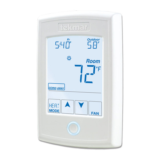
The tekmarNet
is a communicating touchscreen
thermostat designed to operate one
or two heating stages, one cooling
stage, a fan and relative humidity.
A Watts Water Technologies Company
®
Thermostat 553
®
Thermostat 553
Energy Saving Features
•
Programmable Schedule
•
Zone Synchronization
•
Zone Post Purge
•
Warm Weather Shut Down
•
Cooling Interlock
•
Auto Heating Cycle
•
Temporary Hold
•
Away Scene Key
Additional Features
•
2 Auxiliary Sensor Inputs
•
tekmarNet
Compatible
•
Touchscreen Technology
•
Outdoor & Floor Temperature
Display
•
Backlight
•
Radiant Floor Heating & Cooling
•
Freeze Protection
•
Pump & Valve Exercising
•
Heat / Cool Priority
•
Air Group Master & Member
•
Network Schedule Master or
Member
•
Optimum Start
•
Scenes
•
Daylight Savings Time
•
Room Temperature Limiting
•
Relative Humidity Control
1 of 48
553 _ D
Zoning
Replaces: New
®
Communication
© 2013
553_D - 04/13
04/13
Advertisement
Table of Contents
Troubleshooting

Related Manuals for Tekmar tekmarNet 553


Summary of Contents for Tekmar tekmarNet 553
-
Page 1: Energy Saving Features
553 _ D 04/13 tekmarNet ® Thermostat 553 Zoning Replaces: New Installation & Operation Manual Introduction Energy Saving Features • Programmable Schedule ® The tekmarNet Thermostat 553 • Zone Synchronization is a communicating touchscreen • Zone Post Purge thermostat designed to operate one or two heating stages, one cooling •... -
Page 2: Table Of Contents
Return Procedure ......48 Toolbox Menu ......21-23 Setup Menu......24-30 Getting Started Congratulations on the purchase of your new tekmar ® thermostat. This manual will step through the complete installation, programming and sequence of operation for this control. At the back, there are tips for control and system troubleshooting. -
Page 3: Installation
- -- ---- - - ---- - - - - - --- - - - - - - - - - - - - - - - - - - - - - - - - - - - - - - - - - Tools Required • tekmar or jeweller screwdriver • Wire Stripper •... -
Page 4: Mounting The Thermostat Base
Mounting The Thermostat Base If a single gang box is used: Stud • Feed the wiring through Thermostat Thermostat the large hole of the Base Front thermostat base. • Fasten the base of the thermostat to the gang box. ” (83 mm) •... -
Page 5: Compatible Sensors
If the thermostat display continues to be off, or is cycling on and off, there may be a fault on the thermostat. If a fault is suspected, contact your tekmar sales representative for assistance. - - - - -- -- - - - - - - - -- -- - - -- - -- - - - - - - - - - - - - - - - - - - - - - - - - - - ®... -
Page 6: Mounting The Thermostat
User Test Sequence Heat Test Cool Test Step Relay(s) Closed Step Relay(s) Closed O RELAY ON Rc to G/O O RELAY OFF Rc to G/O B RELAY OFF Rc to G/O B RELAY ON Rc to G/O FAN ON Rc to G/O FAN ON Rc to G/O (conventional) -
Page 7: Switch Settings
Switch Settings tekmarNet Back of Switch Thermostat 553 Thermostat Settings Two Stage Heat, One Stage Cool, Fan www.tekmarcontrols.com Power: tN2 or 24 V (ac) ±10% 1.8 VA Relay: 24 V (ac) 2 A Designed and assembled in Canada Mmm YYYY Lot # 12345 Meets Class B: ICES &... -
Page 8: User Interface
User Interface Home Screen Display Humidity, Heat Adjust Cool settings, Floor or the Time Outdoor temperature Adjust the Schedule Room Temperature Away Key Turn the Fan on Switch between Auto, Heat, Cool, Off & Return to the Emergency Mode ‘Home’ Screen Home Adjust the from any menu... -
Page 9: Programmable Settings
Programmable Settings Programming Menus Press and hold the Home button for 3 seconds to enter the programming menus. The thermostat returns to the last programming menu previously used. Press and hold for 3 seconds to access the programming menus. - - - - -- - -- - - - - - - - - - - -- - - -- - -- - - - - - - - - - -- -- - - - - ---- - - - - - - - - - - - - - - - - - - - - - - - - - - - - - - - - - Select a Programming Menu •... -
Page 10: Set Temp Menu
Set Temp Menu (1 of 4) Setting Display Room SET HEAT ROOM Set the room heating temperature for the event. Access Level: Installer, User Range: 40 to 95°F (4.5 to 35.0°C) Conditions: Always available. Default: 70°F (21.0°C) Room SET HEAT ROOM Set the room heating temperature for the event. - Page 11 Set Temp Menu (2 of 4) Setting Display SET HEAT FLOOR Set the floor heating temperature for the event. Floor Access Level: Installer, User Range: 40 to 95°F (4.5 to 35.0°C) Conditions: Room Sensor set to OFF and Sensor 1 or Sensor 2 set to Floor and Schedules are in Default: 65°F (18.5°C) use or Scenes are set to All or Guest.
- Page 12 Set Temp Menu (3 of 4) Setting Display COOL MINIMUM ROOM LIMIT Set the minimum room cooling limit while in the event. Access Level: Installer Range: 50 to 100°F (10.0 to 38.0°C) Conditions: Y RELAY is set to HP or AC. Default: 50°F (10.0°C) COOL MINIMUM ROOM LIMIT Set the minimum room cooling limit while in the...
- Page 13 Set Temp Menu (4 of 4) Setting Display TEMPORARY HOLD Temperature adjustment in the home menu can result in either permanent temperature setting change or temporary temperature setting change that lasts 3, 6, 9, 12 hours or until the next scheduled event. Access Level: Installer Range: OFF or ON Conditions: None...
-
Page 14: Time Menu
Time Menu (1 of 1) Setting Display MINUTES Select the current time minutes. Access Level: Installer, User Range: 00 to 59 Conditions: Always available. Default: 00 HOURS Select the current time hours. Access Level: Installer, User Range: 12 AM to 11 PM or 00 to 23 Conditions: Always available. -
Page 15: Schedule Menu
Schedule Menu (1 of 2) The schedule menu can operate on a 24 hour or 7 day repeating schedule. When a 24 hour schedule is selected, “SuMoTuWeThFrSa” is shown on the top of the screen to show that the event time applies to all days of the week. When a 7 day schedule is selected, each individual day of the week is shown with the event time. -
Page 16: Display Menu
Schedule Menu (2 of 2) Setting Display SCHEDULE Select if the thermostat should change the temperature automatically using a programmable schedule. OFF = Programmable schedule is not used. Zone = Applies to this thermostat only. Master 1, 2, 3, 4 = In charge of one of four available network schedules. -
Page 17: Scenes Menu
Display Menu (2 of 2) Setting Display BACKLIGHT Select how the display backlight operates. ON = Always full brightness. DIM = Dim when inactive, on when touched. = Dim in , off in . On when touched. = On in , off in . -
Page 18: Monitor Menu
Monitor Menu (1 of 4) Setting Display ROOM AVERAGE Current room temperature. Displays the average if there are multiple room sensors. Range: -58 to 212°F Access Level: Installer (-50.0 to 100.0°C) Conditions: Sensor 1 or 2 is set to ROOM. Default: Not applicable. - Page 19 Monitor Menu (2 of 4) Setting Display SENSOR 2 The temperature measurement from the sensor 2 input wiring terminals. Range: -58 to 212°F Access Level: Installer (-50.0 to 100.0°C) Conditions: Sensor 2 is set to ROOM, FLOR, or OUT. Default: Not applicable. HUMIDITY LOCAL The built-in relative humidity sensor measurement.
- Page 20 Monitor Menu (3 of 4) Setting Display FLOOR HIGH The highest recorded floor temperature measurement. Touch the number and the ENTER key to reset. Range: -76 to 149°F Access Level: Installer, User (-60.0 to 65.0°C) Conditions: Sensor 1 or 2 is set to FLOR. Default: Not applicable.
-
Page 21: Toolbox Menu
Monitor Menu (4 of 4) Setting Display COOL W HOURS The total number of hours the W relay has been operated for radiant floor cooling. Touch the number and the ENTER key to reset. Access Level: Installer, User Range: 0000 to 9999 hours Conditions: Floor Cool is set to ON and W TERM is Default: 0000 hours set to HRF1 or HRF2. - Page 22 2:01 to 2:24, 3:01 to 3:24 ® Conditions: tekmarNet 2 or 4 detected. Default: AUTO SOFTWARE AND TYPE VERSION Displays the software version and the tekmar type number. Access Level: Installer, User, Limited, Secure Range: 553 Conditions: Always available. Default: 553 22 of 48 A Watts Water Technologies Company ©...
-
Page 23: Toolbox Menu
Toolbox Menu (3 of 3) Setting Display DEVICE COUNT ® Provides a count of all the tekmarNet thermostats and ® setpoint controls on the tekmarNet system. Range: 1 to 24 Access Level: Installer Default: 1 ® Conditions: Must be connected to a tekmarNet system. - Page 24 Setup Menu (1 of 7) Setting Display SENSOR 1 Select the auxiliary sensor input 1 type. Range: OFF, ROOM, FLOR (floor), Access Level: Installer COIL, DUCT Conditions: Always available. Default: OFF SENSOR 2 Select the auxiliary sensor input 2 type. Range: OFF, ROOM, FLOR (floor), Access Level: Installer OUT (outdoor)
- Page 25 Setup Menu (2 of 7) Setting Display W PUMP Select whether the primary or mix system pump on ® a tekmarNet system control should operate while the first stage of heat W is operating. Access Level: Installer Range: OFF or ON ®...
-
Page 26: Setup Menu
Setup Menu (3 of 7) Setting Display W2 PUMP Select whether the primary or mix system pump on ® a tekmarNet system control should operate while W2 is operating. Access Level: Installer Range: OFF or ON Conditions: ACC RELAY is set to W2 and W2 TERMINAL Default: ON is set to CONV or COIL. - Page 27 Setup Menu (4 of 7) Setting Display Y MINIMUM OFF Select the compressor minimum off time. Access Level: Installer Range: 0:30 to 10:00 minutes Conditions: Y RELAY is set to AC or HP. Default: 5:00 minutes COOLING CWSD Select the outdoor temperature below which the cooling system is disabled.
- Page 28 Setup Menu (5 of 7) Setting Display W HEAT WWSD Select the outdoor temperature above which the radiant floor heating is shut off. Range: OFF, 32 to 80°F Access Level: Installer (0 to 26.5°C, OFF) Conditions: Two stage heating with the second stage being a heat pump, fan coil or a furnace and the Default: 60°F (15.5°C) outdoor temperature is available.
- Page 29 Setup Menu (6 of 7) Setting Display AIR GROUP MASTER Select if the thermostat is a master of an air group. Access Level: Installer Range: NONE, 1 to 16 Conditions: The thermostat must be connected to ® other thermostats using tekmarNet and Y RELAY Default: NONE is set to HP or AC.
- Page 30 Setup Menu (7 of 7) Setting Display COOL PURGE Select the fan coil or furnace cooling purge based upon either time or on duct air temperature. Range: 0:00 to 3:00 minutes (no duct sensor) or Access Level: Installer OFF, 40 to 70°F (OFF, 4.5 to 21.0°C) (duct sensor required) Conditions: W or W2 is set to COIL or FURN.
-
Page 31: Sequence Of Operation
Sequence of Operation Section A Heat and Cool Applications The 553 can operate in several different combinations of conventional and heat pump applications. Supported conventional heating applications are: Application RH% Options 1 Heat / 1 Cool / 1 Fan / Relative Humidity Humidification Modes 1, 2, 3 Dehumidification Modes 1, 2, 3 2 Heat / 1 Fan / Humidification... - Page 32 -- ----- - - - - - - - - - - - - - - - - - - - - - - -- - -- - -- -- - -- - - --- - - - - - -- - - - - - - - - - - - - - - - - - - - - - - - - - - - - - - - - - - Warm Weather Shut Down When the outdoor air temperature exceeds the Warm Weather Shut Down (WWSD) ®...
-
Page 33: Cooling Operation
The first stage operates on a temperature differential of ±0.7°F (±0.4°C) centered around the heating setpoint. The second stage heat turns on when the temperature drops 0.7°F - W2 Differential setting below the heating setpoint. The second stage is shut off once the temperature reaches the heating setpoint. The second stage W2 is prevented from turning on until the first stage heat W or the heat pump operates for the elapsed time set by the W2 Delay setting. -
Page 34: Mode Operation
Section E Mode Operation The thermostat includes a mode key. Available modes are: • Heat - Allows heating • Cool - Allows cooling • Auto - Automatically switches between heating and cooling as necessary. The interlock time is applied when switching from heating to cooling or from cooling to heating. -
Page 35: Fan Operation
Section G Fan Operation The fan operates together with the air heating or cooling systems. The user can also select to operate the fan manually by pressing the Fan button. This allows the user to choose between Auto and On. “Auto” allows the fan to operate together with heating or cooling but normally the fan is off. - Page 36 The thermostat has three humidification modes. Mode Operation Stand Alone Humidifier Humidifier operates independently of the HVAC system. Available in all modes except off. Humidifier with Fan Humidifier ducted together with HVAC system. The system fan is oper- ated whenever the humidifier is operating. This is only available when operating a conventional heating system with a fan.
-
Page 37: Air Group Operation
Section I Air Group Operation In order to prevent heating and cooling at the same time, this thermostat can operate together with other thermostats on a tekmarNet ® system to form an air group. On older model thermostats the air group functionality was previously described as a cool group. In an air group, one thermostat is assigned as the air group master. -
Page 38: Temperature Adjustment
Section K Temperature Adjustment - - - - - - - - - - - -- -- - - - - - - - - - - - - - - -- - - - - - - - - - - - - - - - - - - - - - - - - - - - - - - - - - Permanent Adjustment - No Schedule When no programmable schedule is used, touch the up or down arrows to permanently set the “Set Heat Room”... -
Page 39: Programmable Schedules
Section L Programmable Schedules Energy savings can be achieved by lowering the heating temperature and increasing the cooling temperature when the building is unoccupied or during the night. When operating on a programmable schedule, a or a symbol is shown in the home menu. -
Page 40: Scenes (System Override)
Section M Scenes (System Override) Scenes provide an easy way to save energy while away on vacation, or override a programmable schedule when plans change. - -- - - -- --- ---- - -- -- --- -- - - - - - - - - - - - - -- - -- -- - -- - -- -- - -- -- - -- - -- -- --- --- ---- ---- --- --- - - - - - - - - - - - - - - - - - - - - - - - - - - - - - - - - - - Away Key This thermostat includes an Away Key to quickly turn down the heating temperatures... -
Page 41: Secondary Temperature Display
- - - - - - - - - - - - - - - -- - -- - - - - - - - - - - - - - - - - - - - - - - - - - - - - - - - - - - - - - - Recommendation on How to Use Scenes Choosing how to use scenes depends on the needs and lifestyle of the customer using the building. -
Page 42: Access Levels
Section O Access Levels The thermostat Toolbox menu supports four access levels: Installer (INST), User (USER), Limited (LTD), and Secure (SEC). The access level can be adjusted when the thermostat is unlocked. There are two locations to lock the thermostat: 1. -
Page 43: Troubleshooting
Troubleshooting Error Messages (1 of 5) Error Message Description SETUP MENU SAVE ERROR The thermostat failed to read the Setup menu settings from memory and has reloaded the factory default settings. The thermostat stops normal operation until all settings in the Setup menu are checked except to provide freeze protection. - Page 44 Error Messages (2 of 5) Error Message Description DISPLAY MENU SAVE ERROR The thermostat failed to read the Display menu settings from memory and has reloaded the factory default settings. The thermostat continues to operate normally while displaying this error. To clear the error, set the access level to Installer and check all settings in the Display menu.
- Page 45 ® The error cannot be field repaired. Contact your tekmar sales representative for repair procedures. ROOM SENSOR OPEN CIRCUIT ERROR Due to an open circuit, the thermostat is unable to read the built-in room temperature sensor.
- Page 46 Error Messages (4 of 5) Error Message Description SYSTEM CONTROL LOST ERROR ® The thermostat can no longer communicate to the tekmarNet system ® control. Check for open or short circuits in the tekmarNet communication ® wiring. The error automatically clears once the tekmarNet system control has been detected.
-
Page 47: Technical Data
Temperature sensor NTC thermistor, 10 kΩ @ 77°F (25°C ±0.2°C) ß=3892 – Included None – Optional tekmar type # 070, 071, 072, 073, 076, 077, 079, 082, 083, 084 A Watts Water Technologies Company 47 of 48 © 2013 553_D - 04/13... -
Page 48: Limited Warranty And Product Return Procedure
Prod- uct was not installed in compliance with tekmar’s instructions and / or the local codes and ordinances; or if due to defective installation of the Product; or if the Product was not used in compliance with tekmar’s instructions.