Table of Contents
Advertisement
Safe Operation Practices • Set-Up • Operation • Maintenance • Service • Troubleshooting • Warranty
O
'
M
peratOr
s
anual
GT 2042, GT 2148, GT 2050, GTX 2154
WARNING
READ AND FOLLOW ALL SAFETY RULES AND INSTRUCTIONS IN THIS MANUAL
BEFORE ATTEMPTING TO OPERATE THIS MACHINE.
FAILURE TO COMPLY WITH THESE INSTRUCTIONS MAY RESULT IN PERSONAL INJURY.
CUB CADET LLC, P.O. BOX 361131 CLEVELAND, OHIO 44136-0019
Printed In USA
Form No. 769-09555
(November 27, 2013)
Advertisement
Table of Contents

Related Manuals for Cub Cadet GT 2042 Garden Tractor


Summary of Contents for Cub Cadet GT 2042 Garden Tractor
- Page 1 READ AND FOLLOW ALL SAFETY RULES AND INSTRUCTIONS IN THIS MANUAL BEFORE ATTEMPTING TO OPERATE THIS MACHINE. FAILURE TO COMPLY WITH THESE INSTRUCTIONS MAY RESULT IN PERSONAL INJURY. CUB CADET LLC, P.O. BOX 361131 CLEVELAND, OHIO 44136-0019 Printed In USA Form No. 769-09555...
-
Page 2: Table Of Contents
See How-to Maintenance and Parts Installation Videos at www.cubcadet.com/tutorials ◊ Call a Customer Support Representative at (800) 965-4CUB ◊ Locate your nearest Cub Cadet Dealer at (877) 282-8684 ◊ Write to Cub Cadet LLC • P.O. Box 361131 • Cleveland, OH • 44136-0019... -
Page 3: Safe Operation Practices
Important Safe Operation Practices WARNING! This symbol points out important safety instructions which, if not followed, could endanger the personal safety and/or property of yourself and others. Read and follow all instructions in this manual before attempting to operate this machine. Failure to comply with these instructions may result in personal injury. - Page 4 Slope Operation A missing or damaged discharge cover can cause blade contact or thrown object injuries. Slopes are a major factor related to loss of control and tip-over Stop the blade(s) when crossing gravel drives, walks, or accidents which can result in severe injury or death. All slopes roads and while not cutting grass.
- Page 5 Service Children Tragic accidents can occur if the operator is not alert to the Safe Handling of Gasoline: presence of children. Children are often attracted to the machine and the mowing activity. They do not understand To avoid personal injury or property damage use extreme the dangers.
-
Page 6: Spark Arrestor
Do not modify engine Periodically check to make sure the blades come to complete stop within approximately (5) five seconds after To avoid serious injury or death, do not modify engine in any operating the blade disengagement control. If the blades way. -
Page 7: Safety Symbols
Safety Symbols This page depicts and describes safety symbols that may appear on this product. Read, understand, and follow all instructions on the machine before attempting to assemble and operate. Symbol Description READ THE OPERATOR’S MANUAL(S) Read, understand, and follow all instructions in the manual(s) before attempting to assemble and operate DANGER—... - Page 8 2 — i ection mportant peration racticeS...
-
Page 9: Assembly & Set-Up
Assembly & Set-Up Contents of Crate • One Garden Tractor • One Operator’s Manual • One Engine Operator’s Manual Connecting the Battery Cables NOTE: This Operator’s Manual covers several models. Tractor features may vary by model. Not all features in this manual are CALIFORNIA PROPOSITION 65 WARNING! applicable to all tractor models and the tractor depicted may differ from yours. - Page 10 Lower Deck Discharge Chute Deflector Adjusting the Seat The discharge chute deflector must be installed before operating To adjust the position of the seat, push the seat adjustment lever the mower. to the left. Slide the seat forward or rearward to the desired position;...
-
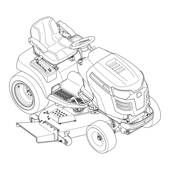
Page 11: Controls & Features
Controls & Features LCD Service Minder & Hour Meter Choke Control Cruise Control/ Parking Brake Lever PTO/Blade Engage Lever Throttle Control Ignition Switch Module Forward Drive Pedal Brake Pedal Steering Tilt Lever Reverse Drive Pedal Electric Lift Switch Cup Holder Storage Compartment Fuel Cap Manual Lift... - Page 12 Manual Lift Lever (If so equipped) Forward Drive Pedal The forward drive pedal is located on the right side of the tractor, along the running board. Press the drive pedal forward to cause the tractor to travel forward. Ground speed is also controlled with the drive pedal. The further forward the pedal is pivoted, the faster the tractor will travel.
- Page 13 Low Gas Window LCD Service Minder & Hour Meter When the ignition key is rotated out of the STOP position but not The low gas window is located at the rear of into the START position, the LCD Service Minder and Hour Meter the tractor.
-
Page 14: Operation
After the engine starts, deactivate the choke control. protection of the operator. If the interlock system should ever malfunction, do not operate tractor. Contact your Cub Cadet dealer. NOTE: Do NOT leave the choke control on while operating the tractor. Doing so will result in a “rich” fuel mixture and cause the •... -
Page 15: Driving The Tractor
Reverse Caution Mode Driving The Tractor WARNING! Avoid sudden starts, excessive speed The REVERSE CAUTION MODE position of the key switch and sudden stops. module allows the tractor to be operated in reverse with the blades (PTO) engaged. NOTE: Mowing in reverse is not recommended. Lightly press the brake pedal to release the parking brake WARNING! -
Page 16: Engaging The Parking Brake
Driving On Slopes Setting The Cruise Control Refer to the SLOPE GAUGE on page 8 to help determine slopes WARNING! Never engage the cruise control lever where you may operate the tractor safely. while traveling in reverse. WARNING! Do not mow on inclines with a slope in excess of 15 degrees (a rise of approximately 2-1⁄2 feet every 10 feet). -
Page 17: Operating The Headlights
Operating the Headlights Mowing The lamps are ON whenever the ignition key is rotated out of the WARNING! Make certain the area to be mowed is STOP position. The lamps turn OFF when the ignition key is free of debris, sticks, stones, wire or other objects that can be thrown by the rotating blades. -
Page 18: Maintenance & Adjustment
Maintenance & Adjustments Maintenance Schedule Before Every Every Every Prior Each use 10 Hours 25 Hours 200 Hours to Storing Check/Clean Engine Intake Screen Clean Hood/Dash Louvers Check Engine Oil Level Check Transmission Oil Change Transmission Oil & Filter * Clean Battery Terminals Lube Front Axles and Rims Lube Pedal Pivot Points... -
Page 19: Hydrostatic Transmission Oil
Do NOT overfill. NOTE: The approved fluid is Cub Cadet Drive System Fluid NOTE: Maintenance, repair, or replacement of the emission control Plus. (1 quart — Part No. 737-3120/1 gallon — 737-3121). - Page 20 Hydrostatic Neutral Adjustment If the tractor creeps forward or rearward when neither the forward nor reverse pedal is depressed, contact your local Cub Cadet dealer to have the hydrostatic control rods properly adjusted. 6 — M & a...
- Page 21 Lubrication Smart Jet Your tractor’s deck is equipped with a water port on its surface as WARNING! Before lubricating, repairing, or part of its deck wash system. inspecting, always disengage PTO, set parking Use the Smart Jet to rinse grass clippings from the deck’s brake, stop engine and remove key to prevent underside and prevent the buildup of corrosive chemicals.
- Page 22 Adjustments Leveling the Deck (Side to Side) If the cutting deck appears to be mowing unevenly, a side to side WARNING! Shut the engine off, remove the adjustment can be performed. Adjust if necessary as follows: ignition key and engage the parking brake before With the tractor parked on a firm, level surface, place the making adjustments.
- Page 23 Wheel Alignment Steering/Toe-in Adjustment The front wheels should toe-in approximately 1⁄8 to 1⁄4”, as To adjust front wheel toe-in, proceed as follows: measured across dimensions A and B. See Figure 6-9. Check the steering gear to ensure it is in the centered position.
- Page 24 Pivot Bar Adjustment CAUTION: The tractor should be checked every 50 hours of operation for play between the frame channel and the pivot bar. Check and adjust the pivot axle as follows: Raise the front of the tractor and set it on jack stands, so the front wheels are suspended above the ground.
-
Page 25: Service
Service Battery Note which battery tray hole the RH side of the hold-down rod is hooked into. Common Causes For Battery Failure Rotate the hold-down rod upward, over and around the battery to unhook from the battery tray. Overcharging Lift the battery out off the battery tray and remove from Undercharging the tractor. - Page 26 Headlights Cutting Deck Removal Refer to Replacement Parts section when replacement of head To remove the cutting deck, proceed as follows: lamp bulbs is necessary. Place the PTO/Blade Engage switch in the disengaged Replace headlight bulbs as follows: (OFF) position and engage the parking brake. Fully raise the hood of the tractor.
-
Page 27: Cutting Blades
Cutting Blades Carefully remove the PTO belt around the deck drive pulley, Feed the belt forward and remove it from around the mule WARNING! Shut the engine off and remove drive pulleys and the tractor’s PTO clutch pulley. ignition key before removing the cutting blade(s) for Looking at the cutting deck from the left side of the tractor, sharpening or replacement. - Page 28 Changing the Deck Belt To properly sharpen the cutting blades, remove equal amounts of metal from both ends of the blades along the WARNING! cutting edges, parallel to the trailing edge, at a 25°- to 30° The V-belts found on your tractor are angle.
- Page 29 42” Deck 48: Deck 7 — S ection ervice...
- Page 30 50” Deck 54” Deck 7— S ection ervice...
-
Page 31: Troubleshooting
Troubleshooting Problem Cause Remedy Excessive vibration 1. Cutting blade loose or unbalanced. 1. Tighten blade and spindle. 2. Damaged or bent cutting blade. 2. Replace blade. Mower will not mulch grass 1. Engine speed too low. 1. Place throttle in FAST (rabbit) position. (If equipped) 2. -
Page 32: Replacement Parts
Replacement Parts Component Part Number and Description 759-3336 Spark Plug KH-52-050-02-S1 Oil Filter KH-24-050-13-S Fuel Filter KH-47-883-03-S1 Fuel Filter 954-0645A Deck Belt, 42” Deck 754-04045 Deck Belt, 48” Deck 954-04118 Deck Belt, 50 & 54” Deck 954-04055 PTO Belt 942-04374 21”... - Page 33 Component Part Number and Description 951-12725 Fuel Cap 946-04759A Choke Control Cable 946-04771A Throttle Control Cable 925-05000 Ignition Key 925-0963 12V Bulb 734-04155 Deck Wheel Phone (800) 965-4CUB to order replacement parts or a complete Parts Manual (have your full model number and serial number ready).
-
Page 34: Attachments & Accessories
Attachments & Accessories Part No. Part 19A40003100 42” Bagger 19A40004100 48/50/54” Bagger 19A40021100 42” Mulch Kit 19A70016100 48” Mulch Kit 190-193-100 50” Mulch Kit 19A70023100 54” Mulch Kit 19A40022100 Dozer Blade 19A40020100 Snow Thrower 490-241-0026 Tire Chains 190-307-100 Weight Kit 490-900-M059 Extra Weight 490-290-0013... - Page 35 Notes...
- Page 36 11— n ection oteS...
- Page 37 11 — n ection oteS...
-
Page 38: Warranties
FEDERAL and/or CALIFORNIA EMISSION CONTROL WARRANTY STATEMENT YOUR WARRANTY RIGHTS AND OBLIGATIONS MTD Consumer Group Inc, the United States Environmental Protection Agency (EPA), and for those products certified for sale in the state of California, the California Air Resources Board (CARB) are pleased to explain the evaporative emission control system (ECS) warranty on your 2013-2014 small off-road equipment (outdoor equipment). - Page 39 WARRANTED PARTS: The repair or replacement of any warranted part otherwise eligible for warranty coverage may be excluded from such warranty coverage if MTD Consumer Group Inc demonstrates that the outdoor equipment has been abused, neglected, or improperly maintained, and that such abuse, neglect, or improper maintenance was the direct cause of the need for repair or replacement of the part.
- Page 40 In the U.S.A. original proof of purchase and applicable maintenance records to the Check your Yellow Pages, or contact Cub Cadet LLC at P.O. Box 361131, servicing dealer. Please see the operator’s manual for information on Cleveland, Ohio 44136-0019, call 1-877-282- 8684 required maintenance and service intervals.