Sharp MD-MS722H Service Manual
Hide thumbs
Also See for MD-MS722H:
- Operation manual (48 pages) ,
- Manuel de fonctionnement (52 pages) ,
- Operation manual (149 pages)
Table of Contents
Advertisement
SAFETY PRECAUTION FOR SERVICE MANUAL ............................................................................................................... 2
SPECIFICATIONS ................................................................................................................................................................. 3
NAMES OF PARTS ............................................................................................................................................................... 4
OPERATION MANUAL .......................................................................................................................................................... 6
DISASSEMBLY ...................................................................................................................................................................... 9
INSTALLING THE TOP CABINET ......................................................................................................................................... 9
REMOVING AND REINSTALLING THE MAIN PARTS ....................................................................................................... 10
ADJUSTMENT ...................................................................................................................................................................... 11
BLOCK DIAGRAM ............................................................................................................................................................... 27
SCHEMATIC DIAGRAM/WIRING SIDE OF P.W.BOARD ................................................................................................... 28
NOTES ON SCHEMATIC DIAGRAM .................................................................................................................................. 35
WAVEFORMS OF CD CIRCUIT .......................................................................................................................................... 36
TROUBLE SHOOTING ........................................................................................................................................................ 37
FUNCTION TABLE OF IC .................................................................................................................................................... 40
PARTS GUIDE/EXPLODED VIEW
SERVICE MANUAL
(Illustration: MD-MS722H)
(Illustration: MD-MS721H)
CONTENTS
SHARP CORPORATION
MD-MS722H
MD-MS721H(BL)
MD-MS721H(S)
• In the interests of user-safety the set should be restored to its
original condition and only parts identical to those specified be
used.
• Note for users in UK
Recording and playback of any material may require consent
which SHARP is unable to give. Please refer particularly to the
provisions of Copyright Act 1956, the Dramatic and Musical
Prefomers Protection Act 1956, the Preformers Protection Acts
1963 and 1972 and to any subsequent statutory enactments and
orders.
This document has been published to be used
for after sales service only.
The contents are subject to change without notice.
- 1 -
MD-MS722H/MS721H
No. SX887MDMS722H
Page
Advertisement
Table of Contents

Related Manuals for Sharp MD-MS722H


Summary of Contents for Sharp MD-MS722H
-
Page 1: Table Of Contents
• Note for users in UK Recording and playback of any material may require consent which SHARP is unable to give. Please refer particularly to the provisions of Copyright Act 1956, the Dramatic and Musical Prefomers Protection Act 1956, the Preformers Protection Acts 1963 and 1972 and to any subsequent statutory enactments and orders. -
Page 2: Specifications
MD-MS722H/MS721H SAFETY PRECAUTION FOR SERVICE MANUAL Precaution to be taken when replacing and servicing the (MS722H Except for (MS722H For UK) Laser Pickup. UK/MS721H) The AEL (Accessible Emission Level) of Laser Power Output for this model is specified to be lower than Class I Require- ments. -
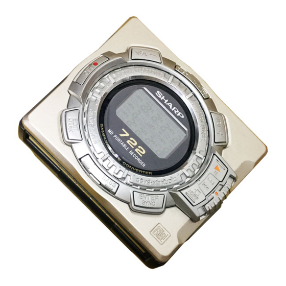
Page 3: Names Of Parts
MD-MS722H/MS721H NAME OF PARTS MD-MS722H Remote control unit 1. Synchro Recording Indicator SYNC 2. Character/Time Information Indicator RANDOM TOTAL 3. Record Indicator 4. Repeat Indicator: 5. Random Indicator 6. Disc Mode Indicator 7. Total Track Number Display 8. Track Number Indicator 9. - Page 4 MD-MS722H/MS721H MD-MS721H Remote control unit 1. Synchro Recording Indicator SYNC 2. Character/Time Information Indicator RANDOM 3. Record Indicator TOTAL 4. Repeat Indicator: 5. Random Indicator 6. Disc Mode Indicator 7. Total Track Number Display 8. Track Number Indicator 9. Battery Indicator: 10.
-
Page 5: Operation Manual
MD-MS722H/MS721H OPERATION MANUAL OPEN OPEN – 6 –... - Page 6 MD-MS722H/MS721H – 7 –...
- Page 7 MD-MS722H/MS721H – 8 –...
-
Page 8: Disassembly
Pull Pull Mechanism Unit 1. Raise the rear part, and remove Pull Pull Pull in the arrow direction. Pull (Illustration: MD-MS722H) (C3)x3 (C2)x1 (C2)x1* Top Cabinet Flexble PWB for (C3)x1 optical pickup Caution: Carefully handle the main PWB and flexible PWB. After removing the... -
Page 9: Removing And Reinstalling The Main Parts
MD-MS722H/MS721H REMOVING AND REINSTALLING THE MAIN PARTS Remove the mechanism according to the disassembling meth- (A2)x3 ø1.4x2.8mm ods 1 to 3. (See Page 9.) How to remove the spindle motor (See Fig. 10-1.) Spindle Motor 1. Remove the solder joint (A1) x 1 of flex PWB. -
Page 10: Adjustment
MD-MS722H/MS721H ADJUSTMENT Test disc MD adjustment needs two types of disc, namely recording disc (low reflection disc) and playback-only disc (high reflection disc). Type Test disc Parts No. High reflection disc MMD-110 (TEAC Test MD) 88GMMD-110 Lowreflection disc MMD-212 (TEAC Test MD) - Page 11 MD-MS722H/MS721H Operation in each TEST mode 1. AUTO1 Mode • When the STOP button is pressed while the AUTO1 menu appears or during automatic adjustment, the mode changes to the TEST mode stop state. At this time the adjustment value is not output.
- Page 12 MD-MS722H/MS721H •Whenever the DISP button is pressed in the continuous playback mode, the indication changes as follows. * Pit section Continuous playback (SUBQ address indication) [ S Q Continuous playback (C1 error indication) [ C E Continuous playback (SUBQ address indication)
- Page 13 MD-MS722H/MS721H 13. INNER Mode • when the STOP button is pressed on the INNER menu (SQ______ ), the state is changed to the TEST mode STOP state. • : Address EEPROM (IC402) writing procedure 1. Procedure to replace EE-PROM and write initial value of microcomputer in EEPROM (1) Replace EEPROM.
- Page 14 MD-MS722H/MS721H EEPROM DATA LIST (EEPROM version f) Sled setting TEMP setting Item display Set values Item display Set values S L G _ T M _ _ Calculate values S L 2 _ Fucus setting S L M _ Item display...
- Page 15 MD-MS722H/MS721H – 16 –...
- Page 16 MD-MS722H/MS721H – 17 –...
- Page 17 MD-MS722H/MS721H – 18 –...
- Page 18 MD-MS722H/MS721H – 19 –...
- Page 19 MD-MS722H/MS721H – 20 –...
- Page 20 MD-MS722H/MS721H – 21 –...
- Page 21 MD-MS722H/MS721H – 22 –...
- Page 22 MD-MS722H/MS721H – 23 –...
- Page 23 MD-MS722H/MS721H – 24 –...
- Page 24 MD-MS722H/MS721H – 25 –...
- Page 25 MD-MS722H/MS721H – 26 –...
-
Page 26: Block Diagram
MD-MS722H/MS721H +2.5 AVCC Figure 27 BLOCK DIAGRAM – 27 –... -
Page 27: Schematic Diagram/Wiring Side Of P.w.board
MD-MS722H/MS721H P29 P30 MAIN PWB-A C112 0.033 PLAYBACK SIGNAL C111 TP202 0.0033 C110 RECORD SIGNAL TP139 C107 0.22 C109 0.012 L204 R207 XL201 C106 1/16 33.8688MHz 0.22 CK207 48 47 46 45 44 43 42 41 40 39 38 37... - Page 28 MD-MS722H/MS721H DADATA HREC ADDATA DFCK TP202 BCLK LRCK JOG0 TP139 JOG1 L204 R207 XL201 ADPON R460 33.8688MHz R455 R456 R457 DAPON 5.6K 8.2K OPTCNT HKEY2 R459 CK207 HSTOP C212 TP211 8P(CH) TP212 TP205 EMPH1 HPLAY C204 0.47 HKEY1 R451 R452...
- Page 29 MD-MS722H/MS721H P28 P29 KEY FLEXIBLE PWB UNIT MS722H FLEXIBLE ONLY DISPLAY TP451 TP452 VOL DOWN TP453 DADATA HREC ADDATA TP454 EDIT DFCK TP455 BCLK TP456 P-MODE LRCK JOG0 TP457 JOG 1 JOG1 TP458 JOG 2 ADPON TP459 R460 R455 R456...
- Page 30 MD-MS722H/MS721H IC101 IC200 IC401 IC501 IC701 IC820 VOLTAGE VOLTAGE VOLTAGE VOLTAGE VOLTAGE VOLTAGE VOLTAGE VOLTAGE 0.7V 2.35V 2.5V 1.25V 0.7V 2.5V 2.48V 2.5V 1.2V 0.7V 1.27V 2.35V 0.96V 0.7V 2.33V 1.29V 1.27V 2.33V 0.95V 1.26V 1.27V 0.7V 3.55V 1.27V 2.35V 1.26V...
- Page 31 MD-MS722H/MS721H J703 REMOTE CONTROL/ J801 HEADPHONES DC IN R800 C804 J702 R809 MIC IN D802 R893 R727 R801 Q892 C725 Q721 C805 R804 IC801 D801 C726 R726 C727 L704 C872 L871 Q891 D861 L862 C807 IC802 F800 C806 L851 C715...
- Page 32 MD-MS722H/MS721H P34 6 - H TP721 TP729 TP726 TP722 D491 C491 D493 TP711 TP802 TP713 L713 L457 L452 C751 L453 L458 C800 L711 TP714 TP805 L456 TP727 TP728 L454 TP801 C752 L714 TP772 TP725 TP484 R482 C703 TP724 C702 IC841 BATTERY,–...
- Page 33 MD-MS722H/MS721H M901 M902 OPTICAL PICKUP UNIT (15) SPINDLE MOTOR SLED MOTOR M903 LIFT MOTOR SW901 DISC IN CN601 SW902 TO MAIN PWB DISC PROTECT P33 11 - H MECHA FLEXIBLE PWB UNIT (8) CN101 TO MAIN PWB P33 8 - H...
-
Page 34: Notes On Schematic Diagram
MD-MS722H/MS721H NOTES ON SCHEMATIC DIAGRAM • Resistor: • The indicated voltage in each section is the one measured To differentiate the units of resistors, such symbol as K and by Digital Multimeter between such a section and the chas- M are used: the symbol K means 1000 ohm and the symbol sis with no signal given. -
Page 35: Waveforms Of Md Circuit
MD-MS722H/MS721H WAVEFORMS OF MD CIRCUIT Stopped 1994 / 12 / 15 22:54:19 Stopped 1994 / 12 / 16 00:24:17 Stopped 1994 / 12 / 16 01:03:40 CH1=1mV CH2=500mV CH3=5V CH4=2V 50ms/div CH1=2V CH2=2V CH3=2V CH4=2V 50us/div CH1=1V CH2=2V CH3=500mV 2ms/div... -
Page 36: Troubleshooting
MD-MS722H/MS721H TROUBLESHOOTING It is advisable to use the TEST mode (refer to Error Data Display Mode, P13) indicating the causes of troubles before starting repair. Causes of operation errors (up to 10 errors) are recorded as error codes. This information is useful for repair. - Page 37 MD-MS722H/MS721H • Abnormal display Is waveform output from CNS 482 pins 1 to 3? Is waveform output from IC 401 pins 45 to 47? Are the pin7 (VCC) and pin 6 (GND) normal? Check the periphery of IC401. Check between IC401 and CNS482.
- Page 38 MD-MS722H/MS721H • The spindle motor fails to run.Does the head move Check the IC201 periphery. Does the waveform appear on the IC201 pins 24 and 25 after TEST mode AUTO2 completion and in this state? Replace IC601. Does waveform appear on the IC601 pin 13? Does waveform appear on IC901 pins 1, 19 and 20? L608, IC201, IC901, CN601 and flex, etc.
-
Page 39: Function Table Of Ic
MD-MS722H/MS721H FUNCTION TABLE OF IC IC401 RH-iX2772AF03(IX2772AF):System Microcomputer (1/2) Port Name Terminal Name Input/Output Function Pin No. P12/TCLKA Input Track cross signal/focus drive detection SPIN Output Spindle motor FG pulse detection input DISCIN Input Disc insertion detection input DISCCPR Input... - Page 40 MD-MS722H/MS721H IC401 RH-iX2772AF03(IX2772AF):System Microcomputer (2/2) Port Name Terminal Name Input/Output Function Pin No. Input Operation mode selection input 1 INNSW Input Mechanism inner SW position detection input WDTOVF WDTOVF Output Watch dog timer (not used) Input Operation mode selection input 2...
- Page 41 “HOW TO ORDER REPLACEMENT PARTS” To have your order filled promptly and correctly, please furnish the For U.S.A. only following information. Contact your nearest SHARP Parts Distributor to order. 1. MODEL NUMBER 2. REF. No. 3. PART NO. 4. DESCRIPTION For location of SHARP Parts Distributor, Please call Toll-Free;...
- Page 42 MD-MS722H/MS721H PRICE PRICE PARTS CODE DESCRIPTION PARTS CODE DESCRIPTION RANK RANK INTEGRATED CIRCUITS L491 VPBNN4R7M0000 AC 4.7 H L500 VPCBM220K0000 AC 22 H L600 RCILC0331AFZZ AC 2.2 H,Choke IC101 VHIIR3R55//-1 AQ RF Signal,Processor,IR3R55 IC200 VHI62FP2002-1 AE 2V Regulator,62FP2002 L601~604 RCILC0358AFZZ AC 4.7 H,Choke...
- Page 43 MD-MS722H/MS721H PRICE PRICE PARTS CODE DESCRIPTION PARTS CODE DESCRIPTION RANK RANK C622 VCKYCY1CB104K AB 0.1 F,16V R106 VRS-CY1JB563J AA 56 kohms,1/16W C651 VCKYTV1CF105Z AB 1 F,16V R154 VRS-CY1JB122J AA 1.2 kohms,1/16W C701,702 VCSATA0JJ106M AD 10 F,6.3V,Electrolytic, R161 VRS-CY1JB122J AA 1.2 kohms,1/16W...
- Page 44 MD-MS722H/MS721H PRICE PRICE DESCRIPTION PARTS CODE PARTS CODE DESCRIPTION RANK RANK R824 VRS-CY1JB394D AA 390 kohms,1/16W MSPRD1360AFFJ AC Spring,Lift Lever R826 VRS-CY1JB224D AA 220 kohms,1/16W LANGF1588AFFW AD Bracket,Pickup R829 VRS-CY1JB153J AA 15 kohms,1/16W RCILH0110AFZZ AM Magnetic Head R830 VRS-CY1JB104J AA 100 kohm,1/16W LX-JZ0154AFZZ AA Screw,ø1.4 2.8mm...
- Page 45 MD-MS722H/MS721H PRICE PRICE PARTS CODE DESCRIPTION PARTS CODE DESCRIPTION RANK RANK GCOVH1302AFZZ AD Cover,LCD [MS722H Only] TINSZ1385AFZZ AP Operation Manual [MS721H] HDECQ0580AFSA J AK Decoration Plate [MS722H] UBAGC0076AFSA AH Carrying Case HDECQ0583AFSA J AH Decoration Plate [MS721H] SSAKP0116AFZZ AD Paper Bag,Unit...
- Page 46 MD-MS722H/MS721H (SW901) (SW902) 502x3 503x2 M901 M902 M903 511x2 518x2 Figure 5 MD MECHANISM EXPLODED VIEW – 5 –...
- Page 47 MD-MS722H/MS721H MS722 MD MECHANISM MS721H ONLY 251x2 606x2 MS721H ONLY 201-5 201-2 202-1 201-4 201-1 201-3 225x2 223x2 225x2 MS721 –A 228x2 204-4 204-1 606x2 204-2 264x3 204-3 202-1 606x2 260x2 202-2 Figure 6 CABINET EXPLODED VIEW – 6 –...
-
Page 48: Packing Method (Md-Ms722H For Uk Only)
MD-MS722H/MS721H PACKING METHOD (MD-MS722H FOR UK ONLY) 10. Strap UBNDT0083AFSA SETTING POSITION OF SWITCHES AND KNOBS 11. Connection Cord, Optical Type QCNWG0422AFZZ UNIT HOLD 12. Operation Manual TiNSE1604AFZZ 13. Carrying Case UBAGC0076AFSA Remote HOLD CANCEL 14. Paper Bag, Unit SSAKP0116AFZZ Control 15.