McIntosh MA6600 Owner's Manual
Integrated amplifier
Hide thumbs
Also See for MA6600:
- Owner's manual (24 pages) ,
- Operation manual (16 pages) ,
- Connection diagrams (2 pages)
Table of Contents

Related Manuals for McIntosh MA6600


Summary of Contents for McIntosh MA6600
-
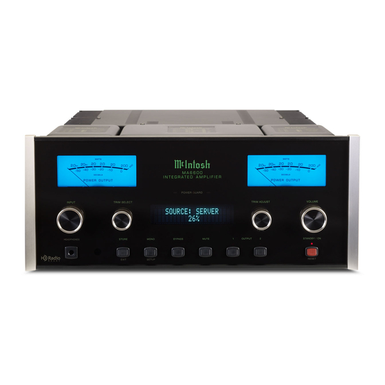
Page 1: Integrated Amplifier
McIntosh Laboratory, Inc. 2 Chambers Street Binghamton, New York 13903-2699 Phone: 607-723-3512 www.mcintoshlabs.com The HD Radio Ready logo is a proprietary trademark MA6600 of iBiquity Digital Corp. Integrated Amplifier Owner’s Manual... -
Page 2: Safety Instructions
The lightning flash with arrowhead, within an equilateral The exclamation point within an equilateral triangle is triangle, is intended to alert the user to the presence of intended to alert the user to the presence of important uninsulated “dangerous voltage” within the product’s en- operating and maintenance (servicing) instructions in the closure that may be of sufficient magnitude to constitute literature accompanying the appliance. -
Page 3: Table Of Contents
McIntosh Laboratory Service Best.” The McIntosh dedication to “Quality,” is as- 2. Apply AC Power to the MA6600 and other McIn- Department. For assistance on factory repair return surance that you will receive many years of musical... -
Page 4: Connector And Cable Information
Input Connectors on the MA6600. Refer grated Amplifier. The Power Amplifier section of volume levels, tone adjustments, setup functions and the MA6600, with a power output of 200 watts per tuner functions when the optional Tuner Module to the diagram for connection:... -
Page 5: Dimensions
Dimensions Dimensions The following dimensions can assist in determining the best location for your MA6600. There is additional information on the next page pertaining to installing the MA6600 into cabinets. Front View of the MA6600 " 44.45cm " " 19.37cm 18.10cm... -
Page 6: Installation
Installation Installation The MA6600 can be placed upright on a table or " 1/16 shelf, standing on its four feet. It also can be custom 43.34cm installed in a piece of furniture or cabinet of your choice. The four feet may be removed from the bottom... -
Page 7: Rear Panel Connections
2, 4 or 8 ohm tosh Component when the loudspeaker to allow control with signals loudspeaker MA6600 is turned On the MA6600 Remote Control Reserved for the installation of optional Tuner RECord OUTPUT Main Fuse holder,... -
Page 8: Connecting Components
19. Connect the Ground Cable coming from the Turn- 8. Connect a Control Cable from the MA6600 another room and/or when the MA6600 is located in a table to the MA6600 GND Binding Post. SERVER DATA PORT Jack to the McIntosh Mu- AC Power Cords Connections: cabinet with the doors closed. -
Page 9: Connecting Loudspeakers
(30.48 meters) shock. Impedance or less or less or less Spade lug or prepared wire connection: 4. Connect the MA6600 Power Cord to a live AC 2 Ohms 12AWG 10AWG 8AWG Insert the spade lug connector or prepared sec- outlet. -
Page 10: Remote Control Push-Buttons
Selects Functions as a “shift” key when used with the AM or FM push-buttons to select Output 1 Selects one of the eight or 2 available Audio Sources Note: Push-buttons whose function is not identified above are for use with other McIntosh Products. -
Page 11: How To Use The Remote Control
Downq Push-button to seek the next available station. trol the rear panel OUTPUTS 1, 2 (ON or OFF). These Note: If at any time the MA6600 seems unresponsive to Press and hold a Channel Upp or Downq Push-but- OUTPUTS provide signals to a Power Amplifier or HRO70 Remote Control Commands press the ton to seek continuously from station to station. -
Page 12: Front Panel Displays, Controls, Push-Buttons And Jack
SOURCE: CD1 Connection for low STANDBY/ON impedance dynamic Push-button with headphones, for indicator switches private listening the MA6600 ON or OFF (Standby) and resets the micropro- cessors IR Sensor receives STORE/EXIT MONO/SETUP Push-button Tone BYPASS Push- MUTE Push-button... -
Page 13: Setup
3. Press the MONO/SETUP Push-button to select the ate enjoyment of superb audio without the need for Firmware in the MA6600 can be identified at any time next Setup Mode Menu item, “Input Level”. With further adjustments. If you wish to make changes to by utilizing the Setup Mode. - Page 14 Figure 7 Control 5. Rotate the TRIM ADJUST Control until Listen- The MA6600 provides the ability to change the default until “IN- ing Volume Level of the SERVER Input is the Input Names to match the components in your system.
-
Page 15: Power Control Triggers
3, 2, 4, 2 and 8 for step C. Figure 10 Refer to Codes are used when the MA6600 is used in the same 5. Press the VOLUME UP/DOWN Push-button on figure 10. location as a McIntosh Preamplifier and/or A/V Con- the Remote Control to verify proper operation. - Page 16 Remote Control Selection The MA6600 responds to Remote Control Codes NORMal (default) or ALTernate. The ALTernate Codes are selected when the MA6600 is used with another McIntosh Remote Controllable Preamplifier, thus preventing both units from responding to the same Remote Control Commands.
- Page 17 Notes...
-
Page 18: How To Operate The Ma6600
Meter Illumination. The Trim The Red LED above the STANDBY/ON Push-button and 17. Settings are stored in memory lights to indicate the MA6600 is in Standby mode. To independently for each Input SOURCE: CD1 Switch ON the MA6600, press the STANDBY/ON... - Page 19 How to Operate the MA6600 The Front LEVEL + / - Push-buttons to increase (refer to fig- The Front BALANCE 50 dB TREBLE: -12 dB Panel Dis- ure 24) or decrease (refer to figure 25) the volume Panel Dis- ¦ ¦ ¦ ¦ ¦ ¦ ¦ ¦ ¦ ¦...
- Page 20 METER ILLUMINATION Note: For information on how the Front Panel Informa- tion Display Brightness can change with the Me- mation The MA6600 Front Panel Meter Illumination may be TRIM LEVEL: 0.0 dB ter Illumination setting, refer to page 15 “Display Display.
- Page 21 OUTPUT connectors (Output 1 and 2), yet listening cycle of a 2,000Hz tone burst. amplifier with a MA6600. The first way is to use the separate amplifier instead of the MA6600 built-in with headphones will continue until the Mute Push- button is pressed again for 3 seconds.
- Page 22 Power Amplifier (to drive Loudspeakers in another MA6600 will resume normal operation. room) and an external sensor for remote operation of Note: This can be performed with the MA6600 On or in the Standby Mode. the MA6600 from that room. With an external Power...
- Page 23 Notes...
-
Page 25: Photos
Photos... -
Page 26: Specifications
0.005% maximum with both channels operating from Phono, 47K ohms; 65pF Standby: Less than 1 watt Note: Refer to the rear panel of the MA6600 for the cor- 250 milliwatts to rated power, 20Hz to 20,000Hz Power Amp In, 10K ohms rect voltage. -
Page 27: Packing Instructions
#10 flat washer 1-3/4 inch needed, please call or write Customer Service Depart- 017937 Plastic foot ment of McIntosh Laboratory. Refer to page 3. Please 400159 #10-32 x 3/4 machine screw see the Part List for the correct part numbers. - Page 28 McIntosh Laboratory, Inc. 2 Chambers Street Binghamton, NY 13903 www.mcintoshlabs.com The continuous improvement of its products is the policy of McIntosh Laboratory Incorporated who reserve the right to improve design without notice. Printed in the U.S.A. McIntosh Part No. 04115001...