Table of Contents
Advertisement
INSTALLER/cONSUMER
SAFETY INFORMATION
pLEASE READ THIS MANUAL
BEFORE INSTALLING AND
USING AppLIANcE
WARNING!
IF THE INFORMATION IN THIS
MANUAL IS NOT FOLLOWED
ExAcTLY, A FIRE OR ExpLO-
SION MAY RESULT cAUSING
pROpERTY DAMAGE, pER-
SONAL INjURY OR LOSS OF
LIFE.
FOR YOUR SAFETY
Installation and service must
be performed by a qualified
installer, service agency or
the gas supplier.
WHAT TO DO IF YOU SMELL GAS:
• Do not try to light any appliance.
• Do not touch any electric switch;
do not use any phone in your
building.
• Immediately call your gas
supplier from your neighbor's
phone. Follow the gas suppliers
instructions.
• If you cannot reach your gas
supplier call the fire department.
DO NOT STORE OR USE
GASOLINE OR OTHER FLAM-
MABLE VAPORS AND LIQUIDS
IN THE VICINITY OF THIS OR
ANY OTHER APPLIANCE.
This appliance may be installed in
an after market permanently located
manufactured (mobile) home where not
prohibited by local codes.
This appliance is only for use with the
type of gas indicated on the rating plate.
This appliance is not convertible for use
with other gases unless a certified kit is
used.
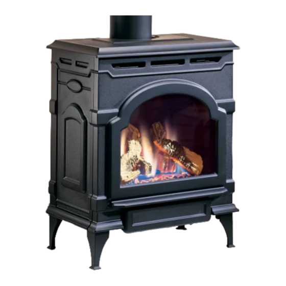
Oxford Direct Vent /
Natural Vent Gas Heater
Models: OxDV30NV
Homeowner's Installation
and Operating Manual
INSTALLER: Leave this manual with the appliance.
cONSUMER: Retain this manual for future reference.
1935
Dutchwest
gas stove
cover
5/03
C E RT I F I E D
30005123 4/10 Rev. 2
Advertisement
Table of Contents

Related Manuals for MHSC Oxford OXDV30NV

Summary of Contents for MHSC Oxford OXDV30NV
-
Page 1: Safety Information
INSTALLER/cONSUMER SAFETY INFORMATION pLEASE READ THIS MANUAL BEFORE INSTALLING AND USING AppLIANcE WARNING! Oxford Direct Vent / IF THE INFORMATION IN THIS MANUAL IS NOT FOLLOWED Natural Vent Gas Heater ExAcTLY, A FIRE OR ExpLO- SION MAY RESULT cAUSING Models: OxDV30NV pROpERTY DAMAGE, pER- SONAL INjURY OR LOSS OF LIFE. -
Page 2: Table Of Contents
Table of contents pLEASE READ THE INSTALLATION & OpERATING INSTRUcTIONS BEFORE USING AppLIANcE. Thank you and congratulations on your purchase of an MHSc stove. IMpORTANT: Read all instructions and warnings carefully before starting installation. Failure to follow these instructions may result in a possible fire hazard and will void the warranty. -
Page 3: General Information
Oxford Direct Vent / Natural Vent Gas Heater General Information The Oxford Direct Vent/Natural Vent Room Heater, Model WARNING: Operation of this heater when not connected No. OXDV30NV, is a vented gas appliance listed to the ANSI to a properly installed and maintained venting system standard Z21.88-2009 and CSA-2.33-2009 for Vented Room can result in carbon monoxide (cO) poisoning and pos- Heaters, and CSA 2.17-M91, Gas-Fired Appliances For Use... -
Page 4: Requirements For The Commonwealth Of Massachusetts
Oxford Direct Vent / Natural Vent Gas Heater Installation Requirements Requirements for the commonwealth of Inspection Massachusetts The state or local gas inspector of the side wall horizontally vented gas fueled equipment shall not All gas fitting and installation of this heater shall only be approve the installation unless, upon inspection, the done by a licensed gas fitter or licensed plumber. -
Page 5: Instructions Stove Dimensions
The Draft Hood Adapter is available in the 7FSDHASK stove kit or as a separate item. When the stove is converted to Natural Vent, it uses 4” vent pipe. For aesthetic purposes the MHSc direct vent system may be used up to the ceiling. -
Page 6: Installation Requirements
Oxford Direct Vent / Natural Vent Gas Heater Installation Requirements The installation must conform with local codes or, in Direct Vent System Only the absence of local codes, with the National Fuel Gas Code, ANSI Z223.1/NFPA 54 - latest edition. (EXCEP- TION: Do not derate this appliance for altitude. -
Page 7: Parallel & Corner Installation
D: Max. Alcove Depth 48” (1220 mm) Sidewall Clearance 4” (102 mm) Stove Clearance A: 4” (102 mm) * needed for installing DuraVent Minimum Vent Kit #2792 or MHSC Mini- ST1122 mum Vent Kit #7TFSDVSK. Pipe Centerline B: 14Z\x” (370 mm) ST129c Fig. -
Page 8: Gas Specifications
Oxford Direct Vent / Natural Vent Gas Heater Horizontal Termination - Gas Specifications Direct Vent ONLY Max. Min. Input Input The vent must rise vertically a minimum of 24” (610 Model Fuel Gas control BTU/h BTU/h mm) off the top of the unit, before the first elbow. The 2465 Millivolt 28,000... -
Page 9: Vertical Termination - Direct Vent Only
Oxford Direct Vent / Natural Vent Gas Heater Vent Termination clearances Vertical Termination - Direct Vent ONLY When planning the installation, consider the location A vertical vent system must terminate no less than 8’ of the vent terminal and clearances. Some of the most (2.44 m) and no more than 40’... - Page 10 Do not locate termination hood where excessive snow or ice build up may occur. Be sure to check vent termi- • Only MHSc and Simpson DuraVent venting com- nation area after snow falls, and clear to prevent ac- ponents specifically approved and labelled for cidental blockage of venting system.
-
Page 11: General Venting Information - Termination Location
2. The special venting system used on Direct Vent appliances are certified as part of the appliance, with clearances tested and approved by the listing agency. 3.MHSC assumes no responsibility for the improper performance of the appliance when the venting system does not meet these requirements. -
Page 12: Termination Clearances
Oxford Direct Vent / Natural Vent Gas Heater Termination Clearances Termination clearances for buildings with combustible and noncombustible exteriors. Inside Corner Alcove Applications* Outside Corner Combustible 6" (152 mm) Combustible 6" (152 mm) Noncombustible 2" (51 mm) Noncombustible 2" (51 mm) Balcony - Balcony - with no side wall... -
Page 13: Venting Requirements And Options - Direct Vent Only
(1) Side Wall Termination nents specified on this page. These parts are available from (1) Firestop DuraVent Corporation or your MHSC Dealer. (1) Zero-clearance sleeve Refer to Figure 4 for dimensions relevant to the standard (1) Hardware package minimum-vent kits. -
Page 14: Install The Optional Fan
Oxford Direct Vent / Natural Vent Gas Heater • Remove retaining nut from shaft of rheostat. (if Install the Optional Fan preinstalled) If you are installing the optional convection Fan Kit • Insert the rheostat through the hole in the back #2767 (FK26), continue here. -
Page 15: Venting System Assembly - Direct Vent
First Section of Vent Pipe Install the Vent Adapter pipe #8 x 1/2” Sheet (MHSc Vent components) Metal Screws 1. Install the Restrictor plate. Consult the ‘Vent Run Specifications’ on Page 8 to determine whether the restrictor plate is needed. If so, put the restrictor 4”... -
Page 16: Install Vent Adapter Pipe (Simpson Dura-Vent Components)
Using the starter pipe assembly listed on Page Figure 22. 7, slide the inner section out to allow access. • Run a bead of sealant around the bottom end of MHSc System 9C\,” the starter pipe and attach the assembly to the stove (240 mm using three 1/4-20 x 3/8”... - Page 17 • Slide the wall plate over horizontal run before at- taching the horizontal run to the elbow. Fasten wall plate to wall. 4. For MHSC Vent Pipe only: If necessary, measure to determine the vertical length (X) of pipe required from the adapter pipe to the wall cutout centerline, ST215 including a 2”...
-
Page 18: Vent Termination Below Grade
2. Plumb to the center of the inner (4”) flue collar from the ceiling above, and mark that location. 3. cut the opening: 4” Clearance MHSc System: 9C\,” x 9C\,” (240 x 240mm) DuraVent System: 10” x 10” (254 x 254mm) Gravel 4. Plumb any additional opening through the roof or other construction that may be needed. -
Page 19: Venting System Assembly - Natural Vent
The heater is approved for installation as a Natural overall height. Vent. MHSC Direct Vent pipe could be used directly 11. Apply cement to the inner and outer termination col- after the Draft Hood Adapter up to the ceiling, then lars and install the terminal cap. -
Page 20: Install The Log Set
Oxford Direct Vent / Natural Vent Gas Heater Attach the first section of venting to the draft hood. De- Left Log Right Log pending on the length of the individual venting sections and the lengths of the decorative pipe (if installed), you may need to slip the decorative pipe over the venting sections before attaching upper sections to lower ones. -
Page 21: Burner Information
Oxford Direct Vent / Natural Vent Gas Heater In the U.S.; Gas connection should be made in ac- Air Shutter Adjustment Instructions cordance with current National Fuel Gas Code, ANSI Z223.1/NFPA 54. Since some municipalities have To adjust the air shutter, the following procedures additional local codes, be sure to consult your local should be followed: authority. -
Page 22: Complete The Assembly
Oxford Direct Vent / Natural Vent Gas Heater 8. The air shutter is located on the bottom of the burner Should color need further adjustment, repeat steps 1 to the left. (Fig. 37) Unfasten the two nuts holding - 12 for air shutter adjustment. the shutter in place. -
Page 23: Thermostat Connection (Optional)
Oxford Direct Vent / Natural Vent Gas Heater Thermostat connection (optional) Use only a thermostat rated for 500 millivolts. Check the table below for the appropriate gauge ther- mostat wire to use for the length of lead required in your installation. -
Page 24: Operation
Oxford Direct Vent / Natural Vent Gas Heater Operation Flame & Temperature Adjustment Your First Fire For stoves equipped with HI/LO valves, flame adjust- Read these instructions carefully and familiarize your- ment is accomplished by rotating the HI/LO adjustment self with the burner controls. Locate the pilot assembly, knob located near the center of the gas control valve. -
Page 25: Lighting And Operating Instructions
Oxford Direct Vent / Natural Vent Gas Heater Lighting and Operating Instructions FOR YOUR SAFETY READ BEFORE LIGHTING WARNING:If you do not follow these instructions exactly, a fire or explosion may result causing property damage, personal injury or loss of life. A. -
Page 26: Troubleshooting - Sit Nova 820 Gas Control System
Oxford Direct Vent / Natural Vent Gas Heater Troubleshooting the Gas control System SIT NOVA 820 MILLIVOLT VALVE NOTE: Before trouble shooting the gas control system, be sure external gas shut off is in the “On” position. possible causes Symptom corrective Action 1. -
Page 27: Fuel Conversion Instructions
Oxford Direct Vent / Natural Vent Gas Heater Fuel conversion Instructions WARNING! This conversion kit shall be installed Remove Screws Rear Log Bracket by a qualified service agency in accordance with the manufacturer’s instructions and all applicable Pilot codes and requirements of the authority having jurisdiction. - Page 28 Oxford Direct Vent / Natural Vent Gas Heater pilot type 2 • Loosen pilot hood turning counterclockwise using a 7/16” wrench. (Fig. 54) NOTE: You may use penetrating oil to prevent pilot hood threads from seizing up. • Remove pilot orifice with needlenose pliers. (Fig. 55) NOTE: Use a wrench to hold pilot tube in place while removing the orifice.
- Page 29 Oxford Direct Vent / Natural Vent Gas Heater 25.Replace logs. Left Burner Leg 26.Replace glass and stove front. Conversion is complete. Injector Shoulder 90¡ ST353 Fig. 56 Be sure to maintain 90° angle at left burner leg. ST353 air shutter adjust burner replace 3/20/00 Table 2.
-
Page 30: Maintenance
6. Replace the glass panel and frame assembly. Glass Replacement 7. Replace the Stove Front. Replace glass only with MHSC approved parts. Refer to Page 33 for Replacement Parts. Refer to Figure 58 and previous instructions for removal of the damaged glass frame. -
Page 31: Gasket Replacement
Oxford Direct Vent / Natural Vent Gas Heater Inspect the Vent System Annually Have the vent system inspected annually by a qualified technician. Shut off the main gas supply before inspect- ing the system. Both the inner exhaust pipe and the out- er combustion supply pipe must be checked to confirm that they are unblocked and in good condition. -
Page 32: Wiring Diagram
Oxford Direct Vent / Natural Vent Gas Heater Wiring Diagrams POWER On/Off Switch Wiring CORD Chassis TP/TH Ground Millivolt Gas Valve Black ST124b Thermostat Optional Thermostat FAN JUNCTION BOX (Optional) Thermostat (Optional) Wiring Strain Relief St124b ON / OFF on/off/switch TP/TH Rheostat wiring... -
Page 33: Replacement Parts
10 8 11 15a,b, 31 36a,b MHSC reserves the right to make changes in design, materials, specifications, prices and discontinue colors and products at any time, without notice. 5123 Oxford Direct Vent / Natural Vent Gas Heater Oxford parts Models OxDV30NV Ref. - Page 34 Oxford Direct Vent / Natural Vent Gas Heater Oxford Direct Vent / Natural Vent Gas Heater Models OxDV30NV (continued) Ref. Description Oxford Glass, DV25 1601691 Glass Frame Assembly - SDV30 30000127 Gasket, Glass - Med. Knit - RDV40 1203702 Pilot Top Convertible 10002266 Pilot Assembly 3Way N/DV RN 0.199.706 10002264...
-
Page 35: Optional Accessories
Oxford Direct Vent / Natural Vent Gas Heater Optional Accessories Fan Kits Remote controls FK26 Fan The remote control allows you to turn the heater on or off from anywhere in the room. Refer to Page 32 for The FK26 fan helps distribute heated air from within wiring diagrams. - Page 36 Oxford Direct Vent / Natural Vent Gas Heater 30005123...
- Page 37 Oxford Direct Vent / Natural Vent Gas Heater 30005123...
- Page 38 Oxford Direct Vent / Natural Vent Gas Heater 30005123...
-
Page 39: Warranty
AND LIMITATIONS a) The fireplace has been operated in atmospheres contaminated by • This new MHSC product must be installed by a competent, autho- chlorine, fluorine, or other damaging chemicals. rized, service contractor. A licensed technician, as prescribed by the b) The fireplace has been subjected to prolonged periods of damp- local jurisdiction must perform any installation/service work. -
Page 40: Energuide
Efficiency Ratings Model EnerGuide Ratings Fireplace Efficiency (%) OXDV30NV 63.0 OXDV30PV 63.0 MHSc 149 Cleveland Drive • Paris, Kentucky 40361 www.mhsc.com...