
Related Manuals for Fujitsu Siemens Computers D1627


Summary of Contents for Fujitsu Siemens Computers D1627
- Page 1 Technisches Handbuch / Technical Manual Mainboard D1627/25 Deutsch / English / Français...
- Page 2 ...des questions techniques ou des problèmes ? Veuillez contacter : Votre partenaire Commercial Votre point de Vente Les dernières informations ainsi que les updates (p.ex. BIOS-Update) par rapport à nos cartes mères sont à votre disposition sur Internet : http://www.fujitsu-siemens.com/mainboards...
- Page 4 Questo manuale è stato stampato su carta da riciclaggio. Denna handbok är tryckt på recyclingpapper. Dit handboek werd op recycling-papier gedrukt. Herausgegeben von/Published by Fujitsu Siemens Computers GmbH Bestell-Nr./Order No.: A26361-D1627-Z121-1-6319 Printed in the Federal Republic of Germany AG 1203...
- Page 5 Deutsch English Mainboard D1627/25 Français Technisches Handbuch Technical Manual Ausgabe Dezember 2003 December 2003 edition...
- Page 6 Alle weiteren genannten Warenzeichen sind Warenzeichen oder eingetragene Warenzeichen der jeweiligen Inhaber und werden als geschützt anerkannt. Copyright ã Fujitsu Siemens Computers GmbH 2003 Alle Rechte vorbehalten, insbesondere (auch auszugsweise) die der Übersetzung, des Nachdrucks, der Wiedergabe durch Kopieren oder ähnliche Verfahren.
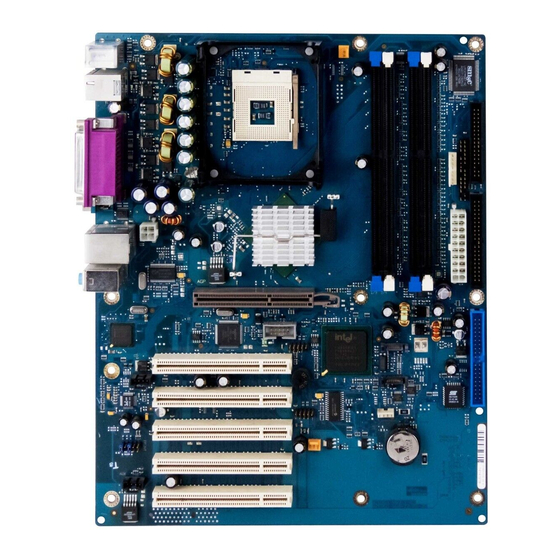
- Page 8 Übersicht/Overview Mainboard D1627/25 Diskettenlaufwerk / Floppy disk drive Interne Anschlüsse und Steckplätze / Internal Stromversorgungsüberwachung / connectors and slots Power supply control Bedienfeld / Front panel Stromversorgung / Power supply IDE-Laufwerke 3/4 / IDE-drives 3/4 IDE-Laufwerke 1/2 / IDE-drives 1/2...
-
Page 9: Table Of Contents
Contents Mainboard D1627/25 ........................1 Notational conventions.......................1 Important notes ..........................2 Information about boards ......................2 List of features...........................3 Special features.........................6 Brief instructions on installing mainboard...................8 Prior to installation ........................8 Interfaces and connectors ......................10 External ports ..........................10 LAN connector.........................10 2, 4 or 6-channel audio mode via analogue audio channels.............11 Internal ports and connectors ......................12... -
Page 11: Mainboard D1627/25
Mainboard D1627/25 Your mainboard is available in different configuration levels. Depending on the configuration chosen, some of the hardware components described may not be available on your mainboard. Additional information Information on the BIOS Setup and additional descriptions of the drivers are contained:... -
Page 12: Important Notes
The equipment and tools you use must be free of static charges. Remove the power plug from the mains supply before inserting or removing boards containing ESDs. Always hold boards with ESDs by their edges. Never touch pins or conductors on boards fitted with ESDs. 2 - English A26361-D1627-Z121-1-6319... -
Page 13: List Of Features
- / - - / - - / - ü ü ü Fujitsu Siemens Computers Keyboard Power Button Support New Intel Pentium processors with 1 Mbyte Second-level-cache are supported. Special onboard features Silent Fan / Silent Fan LT ü / - ü... - Page 14 List of features Internal ports (continued) D1627-E D1627-G D1627-C FireWire™ * (9-Pin, Intel standard header) USB Ports* (2.0, ~480 MB/s) Serial Ports* (FIFO, 16550 compatible) Fan Connectors PSU** / CPU / AUX1 / AUX2 - / 1 / 1 / -...
- Page 15 SmartCard Reader Support (USB / serial) - / - - / - - / - ü Fujitsu Siemens Computers Keyboard Power Button Support New Intel Pentium processors with 1 Mbyte Second-level-cache are supported. Special onboard features ü / - - / ü...
-
Page 16: Special Features
Silent Fan A micro controller developed by Fujitsu Siemens Computers monitors and controls the fans in the PC and thus prevents any unnecessary noise annoyance. Should the processor become in spite of full turning ventilator too hot, then the processor clock rate will automatically be reduced so that the system continues to run stably. - Page 17 If an error occurs during a BIOS update (e. g. due to a power failure), the system BIOS will be destroyed. All Fujitsu Siemens Computers mainboards are equipped with a recovery BIOS. With it a destroyed BIOS can easily be restored. Exact instructions are provided in the chapter "BIOS Recovery - Recovering System BIOS".
-
Page 18: Brief Instructions On Installing Mainboard
USB Security is a BIOS function that offers protection against unauthorised access regardless of the operating system used. If USB Security is activated, the system can only be started, if the MemoryBird of Fujitsu Siemens Computers is connected to one of the existing USB-ports. -
Page 19: Driver Installation
Connect the plugs for the power supply, control panel and drives to the corresponding connections on the mainboard. Driver installation ► Install the drivers for the chipset. You may find the driver on the "Drivers & Utilities" CD. Please refer to chapter "Drivers" for a description of installing drivers. A26361-D1627-Z121-1-6319 English - 9... -
Page 20: Interfaces And Connectors
On: a connection exists (e.g. to a hub). LED flashes - Link Mode: the LAN connection is active. LED 1 (yellow) OFF: 10 Mbit/s On: 100 Mbit/s and WOL mode: a Magic Packet is being received. 10 - English A26361-D1627-Z121-1-6319... -
Page 21: 2, 4 Or 6-Channel Audio Mode Via Analogue Audio Channels
3 = MIC (centre and subwoofer channel, red) Depending on driver version and operating system the functions may differ from this presentation. If necessary, further information is provided in the respective help system of drivers and software. A26361-D1627-Z121-1-6319 English - 11... -
Page 22: Internal Ports And Connectors
IDE 3/4 (secondary) Serial ATA1 Serial ATA2 2 drives* 2 drives* RAID drive* RAID drives* bootable For additional information, refer to the "BIOS Setup" manual on the "Drivers & Utilities" CD or to the RAID controller discription. 12 - English A26361-D1627-Z121-1-6319... -
Page 23: Pin Assignment Of Internal Ports
"Settings with switches and jumpers" chapter Recovery see "Settings with switches and jumpers" chapter Speaker 0,5 W at 8 Ohm Serial ATA (internal) Signal Signal Transmit data positive Transmit data negative Receive data negative Receive data positive A26361-D1627-Z121-1-6319 English - 13... - Page 24 ATA66 Detect (low asserted) ADR 0 (high asserted) ADR 2 (high asserted) CS 1 (low asserted) CS 3 (low asserted) IDE-LED (low asserted) Audio Aux Signal Left AUX audio input AUX GND AUX GND Right AUX audio input 14 - English A26361-D1627-Z121-1-6319...
-
Page 25: Audio Front Panel
Micro bias Analogue VCC Right line output Right line return not connected Left line output Left line return If the audio front panel is not used, you must plug jumpers on pin pairs 5/6 and 9/10. A26361-D1627-Z121-1-6319 English - 15... -
Page 26: Serial Port 2
DSR 2 SIN 2 RTS2 SOUT 2 CTS 2 DTR 2 RI 2 Firewire (1394) Anschluss / Firewire (1394) connector Signal Signal DCD 2 DSR 2 SIN 2 RTS2 SOUT 2 CTS 2 DTR 2 RI 2 16 - English A26361-D1627-Z121-1-6319... - Page 27 Fan voltage (+12 V, max. 1 A) Fan sense Power supply ATX Signal Signal +3.3V(P3V3P) +3.3V(P3V3P) +3.3V(P3V3P) -12V (P12VN) +5V (VCC) PS on (low asserted) +5V (VCC) Powergood (high asserted) -5V (5PVN) +5V Auxiliary (VCC Aux) +5V (VCC) +12V (P12VP) +5V (VCC) A26361-D1627-Z121-1-6319 English - 17...
- Page 28 Interfaces and connectors Additional power supply ATX12 V Signal Signal +12 V +12 V 18 - English A26361-D1627-Z121-1-6319...
-
Page 29: Settings With Switches And Jumpers
On / inserted System and BIOS Setup password are skipped when the device is switched on and may be changed. Off / not inserted System and BIOS Setup password must be entered when the device is switched on. A26361-D1627-Z121-1-6319 English - 19... - Page 30 The System BIOS executes from floppy drive A: and the inserted "Flash-BIOS- Diskette" restores the System BIOS on the mainboard. Off / not inserted Normal operation (default setting). Reserved - switch 3 and switch 4 (if present) Switch 3 and 4 are reserved. 20 - English A26361-D1627-Z121-1-6319...
-
Page 31: Add-On Modules / Upgrading
(A) with regard to the position (4). The angled corner of the processor can also be at a different location than shown in the illustration. ► Push the lever back down until it clicks into place (5). A26361-D1627-Z121-1-6319 English - 21... -
Page 32: Mounting Heat Sink
Depending on the processor variant, clips may also be supplied for mounting the heat sink that fix it in place. ► When you have mounted the optional fan, connect the fan plug to the corresponding connection on the mainboard. 22 - English A26361-D1627-Z121-1-6319... -
Page 33: Upgrading Main Memory
128, 256, 512 or 1024 Mbyte for one socket A current list of the memory modules recommended for this mainboard is available on the Internet at: www.fujitsu-siemens.com/mainboards. At least one memory module must be installed. Memory modules with different memory capacities can be combined. - Page 34 Push the holders on each side of the memory slot outwards. ► Insert the memory module into the location (1). ► At the same time flip the lateral holders upwards until the memory module snaps in place (2). 24 - English A26361-D1627-Z121-1-6319...
-
Page 35: Upgrading Agp Screen Controllers
PCI IRQ Lines connect AGP slots, PCI slots and onboard components to the interrupt controller. PCI IRQ Lines are permanently wired on the mainboard. Which ISA IRQs are assigned to the PCI IRQ Lines is normally automatically specified by the BIOS (see description in "BIOS Setup"). A26361-D1627-Z121-1-6319 English - 25... - Page 36 PCI slot with IRQ sharing, check whether the expansion card properly supports IRQ sharing with the other devices on this PCI IRQ Line. The drivers of all cards and components on this PCI IRQ Line must also support IRQ sharing. 26 - English A26361-D1627-Z121-1-6319...
-
Page 37: Replacing The Lithium Battery
Press the locking lug in the direction of the arrow; the battery jumps somewhat out of the holder (1). ► Remove the battery (2). ► Push the new lithium battery of the identical type into the holder (3) and press it downward until it engages (4). A26361-D1627-Z121-1-6319 English - 27... -
Page 38: Bios Update
BIOS update BIOS update When should a BIOS update be carried out? Fujitsu Siemens Computers makes new BIOS versions available to ensure compatibility to new operating systems, new software or new hardware. In addition, new BIOS functions can also be integrated. -
Page 39: Microcode Update
Safety for processor on Fujitsu Siemens Computers mainboards If the processor uses an old or incorrect microcode, error-free operation cannot be ensured. Fujitsu Siemens Computers has therefore implemented a function on its mainboards that interrupts the booting process if no suitable microcode is available for the installed processor. -
Page 40: Drivers
Insert the CD "Drivers & Utilities Collection" into the CD-ROM drive. ► If the CD does not start automatically, run the START.EXE programme in the main directory of the CD. ► Select DeskUpdate - Fully automatic installation . ► Follow the instructions on screen. 30 - English A26361-D1627-Z121-1-6319... -
Page 41: Annex
Mainboard current requirement You require a Pentium4 power supply nit as per the ATX12V specification for this mainboard. If you do not have a PC from Fujitsu Siemens Computer, make sure that the power supply unit provides the required amperages. -
Page 42: Apm And Acpi System Status, Energy-Saving Modes
* G = Global status; S = System status The power supply unit must provide sufficiently loadable 5 V standby voltage. To use the WOL functionality the power supply must provide a 5 V auxiliary voltage (5V SB) of at least 1 A. 32 - English A26361-D1627-Z121-1-6319... -
Page 43: Mainboard Revision And Bios Version
. Mainboard Revision The revision status of the mainboard exactly identifies which mainboard you have. It is indicated on a sticker on the edge of the mainboard: D1627-A21 GS 1 05618476 Example Mainboard-Revision BIOS version The BIOS version can be displayed in the BIOS Setup . -
Page 44: Error Messages
Available CPUs do not support the same bus frequency - System halted! Memory type mixing detected Non Fujitsu Siemens Memory Module detected - Warranty void There are more than 32 32 RDRAM devices in the system Check whether the system configuration has changed. If necessary, correct the settings. - Page 45 Keyboard error Check that the keyboard is connected properly. Keyboard error nn nn Stuck Key Release the key on the keyboard ( nn is the hexadecimal code for the key). A26361-D1627-Z121-1-6319 English - 35...
- Page 46 = Group number x = Number of SEs found on the communication bus y = Number of SEs entered in Number of connected SE k1, k2 ... = Device ID of the storage extensions found 36 - English A26361-D1627-Z121-1-6319...
- Page 47 Switch the device off and on again. If the message is still displayed, please contact your sales outlet or customer service centre. Verify CPU frequency selection in Setup The frequency setting for the processor is invalid. Correct the BIOS Setup and the setting. A26361-D1627-Z121-1-6319 English - 37...
-
Page 48: Glossary
Universal Serial Bus GMCH Graphics and Memory Controller Video Graphic Adapter Graphics Performance Wake On LAN Accelerator Inter Integrated Circuit IAPC Instantly Available Power Managed Desktop PC Design I/O Controller Hub Intelligent Drive Electronics IPSEC Internet Protocol Security 38 - English A26361-D1627-Z121-1-6319...