Table of Contents
Advertisement
Quick Links
2-OHM STABLE DESIGN
Minimum Impedance Load is 2-Ohms
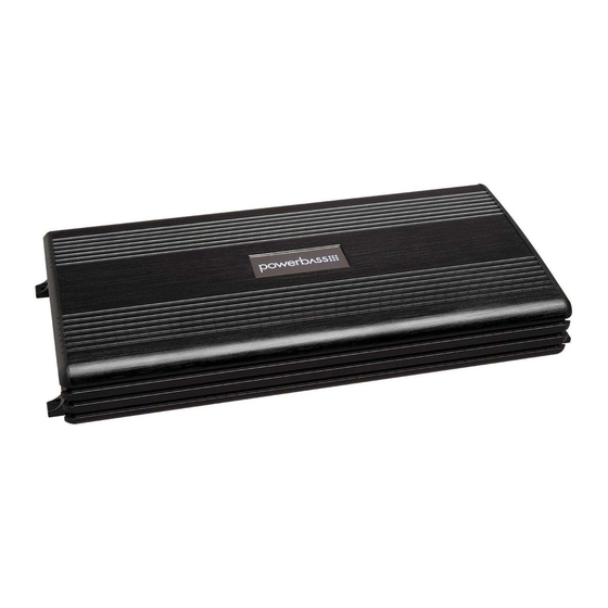
ACA COMPACT A/B MONO BLOCK AMPLIFIER
Please read through this manual to familiarize yourself with your new amplifi er. Should your PowerBass
AutoSound mobile amplifi er ever require service, you will need to have the original dated receipt.
Owners Manual
ACA-250.1
ACA-450.1
Advertisement
Table of Contents

Related Manuals for PowerBass ACA-250.1


Summary of Contents for PowerBass ACA-250.1
-
Page 1: Owners Manual
ACA COMPACT A/B MONO BLOCK AMPLIFIER Owners Manual Please read through this manual to familiarize yourself with your new amplifi er. Should your PowerBass AutoSound mobile amplifi er ever require service, you will need to have the original dated receipt. - Page 2 In the interest of safety, PowerBass USA highly recommends listening at lower volume...
-
Page 3: Technical Features
Remote Level Control (Included) INSTALLATION EXPERIENCE Installation of PowerBass mobile amplifiers requires detailed knowledge of electronics wiring and proper speaker impedance. We strongly recommend installation by an authorized PowerBass dealer. This Own- ers Manual only provides general installation and operation instructions. If you have any reservations about your installation skills, please contact your local PowerBass dealer for assistance. -
Page 4: Installation Precautions
MOUNTING THE AMPLIFIER Fig.1 Mounting Amplifier Due to the high power output of the PowerBass Autosound mono amplifiers, considerable heat may be produced when the unit is in operation. For this reason the amplifier should be mounted in a location which will allow air to circulate freely. -
Page 5: Mounting Location
The floor of the trunk, under the driver’s seat, or on the back of the rear seat. For alternate installation locations, please consult your authorized PowerBass Dealer. NOTE: Do not use a drill with driver bit to mount the amplifier. Excessive force could cause the plastic mounting feet to crack. -
Page 6: Control Panel Layout
CONTROL PANEL LAYOUT Fig.2 Panel Layout NOTE: Panel Layout and Controls may differ by model. 1. REMOTE LEVEL This is the connector port for the Remote Gain Control. Now the amplifiers secondary gain circuit can be adjusted from the driver’s seat. 2. - Page 7 12. REM (Remote Input Terminal) All PowerBass AutoSound amplifiers can be turned on by applying 12 volts to this terminal. This can be found on the rear of the source unit in the form of an electric antenna output, or a remote output. If this is not avail- able you can wire to the ACC position on the key.
- Page 8 Your PowerBass Autosound Mono amp will draw large levels of current, so use the largest gauge power/ ground cable possible. Using too small of power cable can result in unnecessary over-heating of the ampli- fier, distortion at high volume levels and might even cause the thermal protection circuitry to shut-off the amplifier.
- Page 9 BATT+ (Power) This amplifier should be wired directly to the vehicle battery using the appropriate size cable. Start at the vehicle battery and run the power cable through to the amplifier. Avoid running the power cable over engine components and near heater cores. The use of an inline fuse or circuit breaker is a must; this will prevent the risk of a potential fire caused by a short in your power cable.
- Page 10 REM on the amplifier. FUSE REQUIREMENTS While the panel your PowerBass amplifier incorporates one or more fuses, these do nothing to protect the vehicle from a dangerous short circuit. It is absolutely vital that the main power lead to the amplifier(s) in the system be fused within 18-inches (45cm) of the connection to the vehicle battery.
-
Page 11: Rca Interconnect Wiring
RCA INTERCONNECT WIRING Fig.4 Low Level Input using RCA Choose the correct length and style of RCA interconnects for your needs. Always use high quality RCA audio cables (not supplied) for signal connections—those with multiple layers of shielding or a twisted pair variety provides better noise rejection. - Page 12 HIGH LEVEL CONNECTIONS (Optional) High Level inputs have been included to connect the amplifier to a radio without low-level outputs (i.e. factory radio). This connection will allow you to connect directly to the speaker output of the radio without the need of an external adapter.
-
Page 13: Set-Up Adjustments
SET UP ADJUSTMENTS Fig.5 Gain Control Input Gain Adjustment This control allows you to match the input level of the amplifier to the output level of your head unit. Matching the input can be accomplished in four simple steps: Make sure that the remote gain control is not plugged in until after the master gain control is set. Set the GAIN control on the amplifier to Min (completely counter clock wise). - Page 14 Fig.9 Control Module with Pre-wired Plug Remote Level Controller Connection Your PowerBass Autosound Mono amp includes a Remote Level control module. It uses standard telephone wire and telephone RJ45 connectors. To connect the Remote Level Control to the amplifier, simply insert one end of the telephone plug into the REMOTE LEVEL port.
- Page 15 SPEAKER WIRING AND CONFIGURATIONS Speaker Load Keep in mind your PowerBass Autosound Class A/B amp is a high power amplifier and not a high current am- plifier. In other words this amplifier requires a minimum impendance of 2-Ohms mono to operate trouble free.
- Page 16 Speaker Output Configurations 2-OHM STABLE DESIGN Minimum Impedance Load is 2-OHMS 1. A SINGLE VOICE COIL SUBWOOFER SPEAKER Fig.10 A Single Voice Coil Subwoofer (2~4-OHM) 2. TWO SINGLE VOICE COIL SUBWOOFER SPEAKERS Fig.11 Two 4 ohm Subwoofers with Single Voice Coil...
- Page 17 Maintaining proper impedance is critical when wiring the Class A/B model amplifiers. Improper wiring can cause severe damage to BOTH the woofer and the amplifier. Detailed wiring diagrams are supplied with all PowerBass woofers. IF YOU ARE NOT EXPERIENCED OR UNCOMFORTABLE READING THE WIRING DIAGRAMS CONSULT YOUR AUTHORIZED POWERBASS DEALER BEFORE YOU ATTEMPT TO WIRE THE SYSTEM.
-
Page 18: Personal Notes
Miscellaneous: ______________________________________________________ This manual is the exclusive property of PowerBass USA, Inc. Any reproduction of this manual, or use other than its intentions is strictly prohibited without the express consent of PowerBass USA, Inc. © Copyright 2013 PowerBass USA, Inc. -
Page 19: Troubleshooting Tips
NOTE: If the Status L.E.D. is activated and glows RED with no speakers connected to the amplifier, and all the power connections are correct, this would indicate an internal problem with the ampli- fier. Contact PowerBass USA or your local dealer. -
Page 20: Important Notes
SPECIFICATIONS FOR AUTOSOUND COMPACT A/B MONO CLASS AMPLIFIERS ACA-250.1 ACA-450.1 Two Channel Models Power Output @ 14.4 VDC Input 4 Ohms RMS Power (Watts) 150 x 1 300 x 1 2 Ohms RMS Power (Watts) 250 x 1 450 x 1... - Page 21 Some states do not allow limitations on the length of an implied warranty, so this limitation may not apply. No person is authorized to assume for PowerBass any other liability in connection with the sale of this product.
- Page 22 NOTES...
- Page 23 NOTES...
- Page 24 PowerBass Autosound – A division of PowerBass USA, Inc. 2133 S. Green Privado – Ontario, CA 91761 Tel. (909) 923-3868 – Fax (909) 923-8048 www.powerbassusa.com...