Table of Contents
Advertisement
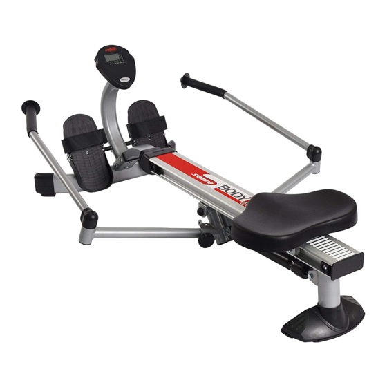
Owner's Manual
CAUTION:
Weight on this product should not exceed 250 lbs.
2004, 10
This Product is Produced Exclusively by
2040 N. Alliance, Springfield, MO 65803
Customer Service Number
1 (800) 375-7520
www.staminaproducts.com
WARNING
Exercise can present a health
risk. Consult a physician
before beginning any exercise
program with this equipment.
If you feel faint or dizzy,
immediately discontinue use
of this equipment. Serious
bodily injury can occur if this
equipment is not assembled
and used correctly. Serious
bodily injury can also occur if
all instructions are not
followed. Keep others and
pets away from equipment
when in use. Always make
sure all bolts and nuts are
tightened prior to each use.
Follow all safety instructions in
this manual.
When calling for parts or
service, please specify the
following number.
35-1050
STAMINA PRODUCTS
MADE IN CHINA
Product May Vary Slightly
From Pictured.
2004 Stamina Products, Inc.
Advertisement
Table of Contents

Related Manuals for Stamina BODYTRAC


Summary of Contents for Stamina BODYTRAC
- Page 1 Weight on this product should not exceed 250 lbs. Product May Vary Slightly From Pictured. This Product is Produced Exclusively by 2040 N. Alliance, Springfield, MO 65803 Customer Service Number 1 (800) 375-7520 www.staminaproducts.com 2004, 10 2004 Stamina Products, Inc.
-
Page 2: Table Of Contents
BODYTRAC using the Read all warnings posted on the BODYTRAC Read this Owner's Manual and follow it carefully before using the BODYTRAC . Make sure that it is properly assembled and tightened before use. Keep children away from the BODYTRAC . - Page 3 CALL US FIRST THANK YOU FOR PURCHASING THE BODYTRAC To help you get started, we have pre-assembled most of your BODYTRAC at the factory with the exception of those few parts left unassembled for shipping purposes. Simply follow the few assembly instructions set forth in this manual.
-
Page 4: Before You Begin
BEFORE YOU BEGIN BODYTRAC Although Stamina tries to manufacture its products Thank you for choosing the with the finest materials and uses the highest take great pride in producing this quality product and standards of manufacturing, occasionally a part that... -
Page 5: Hardware Identification Chart
HARDWARE IDENTIFICATION CHART This chart is provided to help identify the hardware used in the assembly process. After unpacking the unit, open the hardware bag and make sure that you have the following items: 3/16" 1/4" 5/16" 3/8" 1/2" INCHES 100 110 120 130 140 150 MILLIMETERS Place washers, the end of bolts or screws on the... -
Page 6: Assembly Instructions
ASSEMBLY INSTRUCTIONS Place all parts from the box in a cleared area and position them on the floor in front of you. Remove all packing materials from your area and place them back into the box. Do not dispose of the packing materials until assembly is completed. - Page 7 ASSEMBLY INSTRUCTIONS STEP 2 FRONT STABILIZER(28) FRONT SUPPORT(26). METER Insert the Bracket on into the Attach the POST(31) FRONT SUPPORT(28), METER POST(31), FRONT SUPPORT(26), onto the then bolt the FRONT STABILIZER(28) BOLTS(M8 x 15mm)(51) WASHERS(M8)(59). together with Please do not tighten any of these bolts until all six bolts are attached. NOTE: EXTENSION WIRE(38) METER POST(32).
- Page 8 ASSEMBLY INSTRUCTIONS STEP 4 PEDAL SHAFT(32) METER POST(31). PEDAL Insert the through holes located on the Place a SPACER(33) PEDAL(34) PEDAL SHAFT(32) and a onto each end of the and slide them toward the METER POST(31). PEDALS(34) BOLTS(M8 x 15mm)(51) LARGE Then secure the with...
- Page 9 ASSEMBLY INSTRUCTIONS STEP 6 HANDLEBARS(17, 18) EXTENSION ARMS(14) Unfold the and the as shown in the illustration. Attach EXTENSION ARMS(14) PIVOT CONNECTOR(10) LOCKING KNOBS(13). onto the with the STEP 7 METER(37), Install two "AA" batteries into the two batteries included. See page 11 for detailed battery EXTENSION WIRE(39) METER(37).
- Page 10 ASSEMBLY INSTRUCTIONS STEP 8 SEAT ASSEMBLY(42, 43) CENTER BEAM(1). SEAT STOPPERS(3) Slide the onto the Attach the CENTER BEAM(1) BOLTS(M8 x 25mm)(53). onto the back end of the with Also, please verify that the SEAT STOPPERS(3) CENTER BEAM(1) other at the front end of the are assembled at the factory.
-
Page 11: Using The Electronic Meter
USING THE ELECTRONIC METER Power on : Seat movement or push the button. Power off : Automatic shut off after 4 minutes of inactivity. Function Button: MODE/RESET : Press and release to select functions. Press and hold for two seconds to reset all functions to zero, except TOTAL COUNT. -
Page 12: Adjusting Resistance
Worn or damaged components shall be replaced immediately or the BODYTRAC removed from service until repair is made. Only Stamina Products supplied components shall be used to maintain/repair the BODYTRAC Keep your BODYTRAC clean by wiping with an absorbent cloth after use. -
Page 13: Storage
STORAGE To store the BODYTRAC simply keep it in a clean dry place. To avoid damage to the electronics meter, remove the batteries before storing the BODYTRAC for one year or more. Grasp the Front and Rear Stabilizer to move the BODYTRAC . -
Page 14: Conditioning Guidelines
CONDITIONING GUIDELINES How you begin your exercise program depends on your physical condition. If you have been inactive for BODYTRAC several years, or are severely overweight, you must start slowly and increase your time on the gradually: a few minutes per workout. -
Page 15: Warm-Up And Cool-Down
WARM-UP and COOL-DOWN Warm-up The purpose of warming up is to prepare your body for exercise and to minimize injuries. Warm up for two to five minutes before strength-training or aerobic exercising. Perform activities that raise your heart rate and warm the working muscles. Activities may include brisk walking, jogging, jumping jacks, jump rope, and running in place Stretching Stretching while your muscles are warm after a proper warm-up and again after your strength... -
Page 16: Product Parts Drawing
PRODUCT PARTS DRAWING FRONT BACK... -
Page 17: Parts List
PARTS LIST DIAGRAM# PART NAME Center Beam Center Beam Cap Seat Stopper Rear Support Stabilizer Cap Stabilizer Pad Threaded Support Plate Handlebar Support Sensor Support Plate Pivot Connector Pivot Bushion Bumper Knob Locking Knob Extension Arm Extension Arm Bushing Large Washer (3/8") Left Handlebar Right Handlebar Securing Cap... - Page 18 PARTS LIST DIAGRAM# PART NAME Nut Cap (3/8") Screw, Round Head (M3.5 x 12mm) Screw, Round Head (M3.5 x 15mm) Screw, Round Head (M5 x 0.6 x 12mm) Bolt, Round Head (M6 x 1 x 14mm) Bolt, Button Head (M8 x 1.25 x 15mm) Bolt, Button Head (M8 x 1.25 x 20mm) Bolt, Button Head (M8 x 1.25 x 25mm) Bolt, Button Head (M8 x 1.25 x 55mm)
-
Page 19: Warranty
To implement this limited warranty, send a written notice stating your name, date, and place of purchase and a brief description of the defect along with your receipt to Stamina Products, Inc. P.O. Box 1071, Springfield Missouri, USA, 65801-1071 or call us at 1 (800) 375-7520. If the defect is covered under this limited warranty, you will be requested to return the product or part to us for free repair or replacement at our option. -
Page 20: Notes
NOTES... - Page 21 NOTES...
-
Page 22: Fax/Mail Ordering Form
(417) 889-8064. Our Customer Service Department will be able to assist you with your problem and the part will be mailed directly to your house. MAIL TELEPHONE ONLINE STAMINA PRODUCTS, INC. CUSTOMER SERVICE CUSTOMER SERVICE CUSTOMER SERVICE ATTN: Customer Service...