Table of Contents
Advertisement
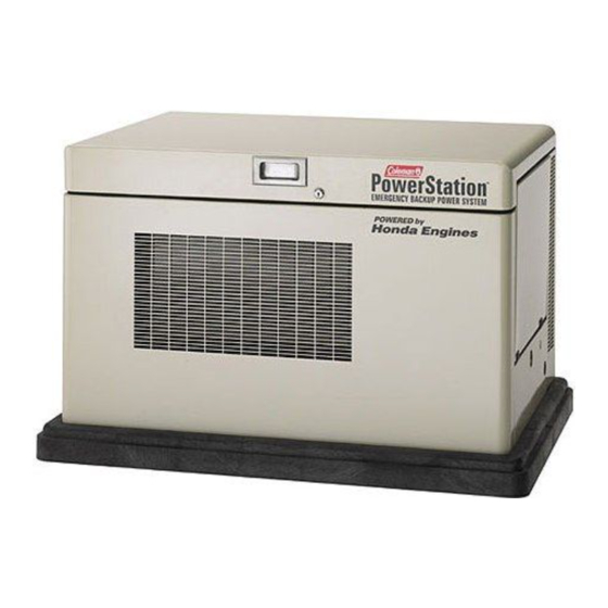
Stationary Standby Electric Generator - 11,000 WATTS - MODEL PM401211
Stationary Standby Electric Generator - 9,500 WATTS - MODEL PM400911
IMPORTANT SAFETY INSTRUCTIONS – Please make certain that persons who are to install, operate and maintain
this equipment thoroughly read and understand these instructions prior to operation. SAVE THESE INSTRUCTIONS
— This manual contains important instructions that should be followed during installation and maintenance of the
generator and battery.
WARNING:
Read and understand all safety precautions in this manual and other
manuals included with this product before installing, operating and maintaining this
equipment. Failure to comply with instructions in this manual could result in personal
injury, property damage, and/or voiding of your warranty. Coleman Powermate WILL
NOT be liable for any damage because of failure to follow these instructions.
Record the model and serial numbers of your generator below:
© 2003 Coleman Powermate, Inc. 1-04
OWNERS MANUAL
MODELS: PM401211
AND PM400911
200-2341 - Revision B
Model Number
____________________
Serial Number
____________________
Date Purchased
____________________
Advertisement
Table of Contents

Related Manuals for Powermate Powermate PM401211


Summary of Contents for Powermate Powermate PM401211
- Page 1 Failure to comply with instructions in this manual could result in personal injury, property damage, and/or voiding of your warranty. Coleman Powermate WILL NOT be liable for any damage because of failure to follow these instructions.
-
Page 2: Table Of Contents
Table of Contents ..............2 General Safety Instructions . - Page 3 The following information relates to protecting YOUR SAFETY and PREVENTING EQUIPMENT PROBLEMS. To help you recognize this information, we use the following symbols. Please read the manual and pay attention to these sections. Also read and follow all safety labels on the engine/generator set. If labels are damaged or unreadable, contact product service for replacements.
- Page 4 WARNING: CAUTION: Units with broken or missing parts, without The National Electrical Code (NEC) requires the protective housing or covers should never be frame and external electrically conductive parts of operated. Contact your service center for the generator to be connected to an approved earth replacement parts.
-
Page 5: Installation Planning
After inspecting the generator, engine and enclosure for physical damage, finish reading the Operating and The stationary standby electric generator is Maintenance Instructions. These manuals contain manufactured for our customers to supply reliable important safety information. W W A A R R N N I I N N G G backup power. - Page 6 W W A A R R N N I I N N G G Proper location of the generator set is important to insure safe and reliable operation and can aid in the installation of the generator. When selecting a site for the •...
- Page 7 Figure 2 Example of Alternative Transfer When connecting the generator to a building Switch Installation electrical distribution system, use of a transfer switch is (Main Panel Load) recommended to isolate the normal utility source from the generator supply. By preventing backfeed of the generator power into the utility lines during a utility power outage, the switch provides a level of safety for electrical line workers.
- Page 8 Once installation planning is complete and all necessary local permits are granted, installation of the generator may begin. Within the following section general recommendations are given for installing the generator. However, installations are affected by local site conditions, regional construction practices, material availability, local or regional codes and/or other variables.
-
Page 10: Main Line Output Power
The output circuit of the generator is 4-wire, 240V, Once the generator is anchored in its final position, it is ready for electrical connections. The generator is rated for the amperage as shown on the generator supplied with two terminal blocks for connection of three nameplate. -
Page 11: Generator Start Signal
A ground fault circuit interrupting (GFCI) receptacle When the control panel mode switch is placed in the is provided with the generator to power the battery AUTO position, generator starting and stopping is charger for reliable starting. It is also intended to power controlled by the opening or closing of a set of voltage an optional block heater if that option is desired. - Page 13 W W A A R R N N I I N N G G The engine driving the generator is engineered to • Natural gas (NG) is highly explosive. provide reliable power on either Liquefied Propane Vapor • Natural gas (NG) is lighter than air and collects (LPG) or Natural Gas.
-
Page 14: Fuel Hookup
Natural Gas (NG) When supplying natural gas as the operating fuel, After electrical connections are complete, the next provide fuel with a minimum of 1000 BTU/ft 3 at inlet installation step is to connect a fuel supply to the unit. The fuel inlet fitting supplied with the generator is male pressures between 7"... -
Page 15: Propane Vapor (Lpg)
Propane Vapor (LPG) In cases where liquefied propane vapor is selected as the fuel of choice, insure fuel delivery in the gaseous state, with a minimum energy content of 2500 BTU/ft 3 , at inlet pressures between 7" and 11" of water column (4 - 6 oz). - Page 16 C C A A U U T T I I O O N N To insure reliable starting in most weather conditions, it is important to properly match a battery to the requirements of the generator. The generator uses a A battery presents a risk of electrical shock and a 12 Volt, direct current, negative ground control system high short circuit current.
- Page 17 that the charger is connected by checking to see that it is plugged into a powered GFCI receptacle, and that the positive (+) and negative (-) charger cables are To install the battery, begin by placing the battery (A) connected to their respective battery cables. into the battery rack as shown in Fig G.
- Page 18 5. Return to the generator and open any manual shutoff valves in the fuel supply system. After completing all installation procedures, read and 6. Move the control panel mode switch to the RUN understand the operating instructions for the generator position.
- Page 19 PM401211 PM400911 Rated Output Propane Vapor 11 kW 9.5 kW Natural Gas 9.9 kW 8.5 kW Rated Amperage Propane Vapor 45.8 A 39.6 A Natural Gas 41.3 A 35.4 A Rated Voltage 240 V 240 V Frequency 60 Hz 60 Hz Phase Single Single...
-
Page 20: Alternator
PM401211 PM400911 Style 2 pole, brushless 2 pole, brushless Synchronous Speed 3600 RPM 3600 RPM Excitation Self regulated Self regulated † † Motor Starting Capacity 12 sKVA 12 sKVA Winding Resistances Stator 0.30 – 0.50 0.30 – 0.50 Excitation 1.4 – 1.6 1.4 –... -
Page 21: Electrical
periods of inactivity to insure reliable, consistent starting. 6. BATTERY CHARGING CIRCUIT FUSE Before installing, operating or maintaining the Protects engine - mounted battery charging generator, take a few moments to become familiar with circuit against damage from electrical faults. the features of the generator as illustrated. - Page 22 the AUTO position sets the generator for unattended operation under the control of a properly matched A standby generator is an engine driven air cooled automatic transfer switch. system to convert the energy contained in either liquid propane vapor or natural gas to electrical power. When B.
- Page 23 fault is declared or until the mode switch is moved to the OFF position. Once the switch is shifted to the OFF Two methods are available to start the generator. position, the engine is shut off. The automatic, or AUTO mode is for use with an When operating with the control panel switch in the automatic transfer switch.
- Page 24 the engine. Once the light is on, the generator does not attempt to start until the fault is reset. Status indicator lights relay conditions of generator When the Overcrank light is on , verify fuel is function for user or service technician convenience. available at the inlet to the unit, then check the Illumination of these indicator lights communicate condition of the cranking battery.
-
Page 25: Generator Operation
To ensure reliable generator operation, it is critical to procedures listed in the following sections. A qualified periodically inspect all components. The following chart generator service technician should perform inspections is provided as a guide for service check intervals. When or adjustments requiring specialized tools or training. - Page 26 Prior to checking the oil level, start the generator by W W A A R R N N I I N N G G moving the Mode switch on the control panel to the RUN position. Allow the generator to run for one or two minutes, then shut it down by returning the switch to the OFF position.
- Page 27 2. Place an oil drain pan capable of holding three (3) quarts under the end of the oil drain hose (A). 3. Remove the oil fill cap (B) and place in a convenient Selection of the correct grade and type of engine oil location.
- Page 28 The generator engine is equipped with a dry element W W A A R R N N I I N N G G air filter to block particles in the combustion air from getting into the engine and causing excessive engine wear.
- Page 29 Fig. F 5. Insure the the battery charger is powered and functioning properly. A correctly operating battery charger displays lights on the face of the charger to relay the state of the charger. To locate the battery charger (A) and check the lights (B) (see note below) refer to Fig F.
- Page 30 tighten new plugs an additional ½ turn, using a 13/16" spark plug wrench to avoid damage to the Engine spark plugs are an important part of the spark plugs. If a torque wrench is available, tighten engine ignition system. Worn or incorrectly adjusted all plugs to 13 in-lbs (18 N-m).
- Page 31 Fig. GG In some areas of the United States, a USDA Forest Service approved exhaust spark arrestor is legally required. This optional accessory is added to the generator during initial installation. To identify whether the generator is equipped with a spark arrestor, inspect the exhaust tailpipe opening for a screen.
- Page 32 C C A A U U T T I I O O N N Proper cooling of the generator is vital to maintain • This adjustment should only be performed by performance and prevent equipment failure. Blocked trained personnel. If incorrect adjustments are cabinet openings or other airflow obstructions are made, the unit may fail to operate or operate potential fire hazards and can cause failures.
- Page 33 Over time, normal engine operation leads to wear in the engine valve train which decreases generator output. To restore generator output, it is necessary to check and adjust the engine valve lash at regular intervals throughout the life of the engine. However, proper valve lash adjustments require specialized training and tools.
- Page 34 SYMPTOM POSSIBLE CAUSE CORRECTIVE ACTION Engine does not crank Loose battery cables • Check all battery cable connections Defective battery • Test battery. Replace as necessary. • Check battery charger inline fuse Improper battery charger function • Ensure charger is plugged into GFCI receptacle •...
-
Page 35: Shutdown
SYMPTOM POSSIBLE CAUSE CORRECTIVE ACTION Low generator output voltage Low engine speed • Verify correct engine speed. Remove excess loads or adjust speed as required. Excitation capacitor failure • Contact a qualified generator dealer for service assistance. Generator diode or varistor failure • Contact a qualified generator dealer for service assistance. - Page 36 Torque to 8.5 lbs-ft Torque to 15 lbs-in Torque to 16 lbs-ft Torque to 17 lbs-ft Torque to 20 lbs-ft Item Part No Description Item Part No Description Screw, 10-16 x .50” lg Screw, m8 x 13 mm lg Star washer, #10 Nut (see Honda manual) Rivet 094-0070...
- Page 37 Torque to 15 lbs-in Item Part No Description Item Part No Description Screw, 10-16 x .50” lg 103-0121 Clip, hood rod Star washer, #10 0056905 Warning label 115-0264 Side panel, left side (includes 094-0084 Insulation (not shown) item 16) 094-0076 Insulation (not shown) S115-0242 Prop arm, lid...
- Page 38 Torque to 7 lbs-ft Torque to 15 -20 lbs-in Torque to 24 lbs-in Item Part No Description Item Part No Description 0056765 Lock (includes 1A, 1B, 1C & 1D) 026-0535 Ground strap, 17” lg 146-0023 107-0062 Hinge (includes (4) item #7) Order item # 1 Washer Rivet...
- Page 39 Torque to 15 lbs-ft ITEM 10 ITEM 11 Item Part No Description Item Part No Description 0056629 Discharge louvered cover 026-0515 Wiring harness, generator 0056623 Engine adapter neutral 160-0311 Rotor assembly 026-0514 Wiring harness, generator power 100-0003 Diode/varistor assembly 160-0309 Complete generator assembly 059-0348 Rotor bolt...
- Page 40 Torque to 8.5 lbs-ft Torque to 15 lbs-in Torque to 40 lbs-ft Detail A detail A For Oil Filter and Air Filter part numbers, see page 19 of this manual. Item Part No Description Item Part No Description 094-0091 Insulation 109-0100 Base, plastic 115-0268...
- Page 41 Torque to 8.5 lbs-ft Torque to 15 lbs-in ITEM 37 Item Part No Description Item Part No Description 094-0096 Insulation 019-0211 Regulator assy, GX670 Hose clamp, 23/32” I.D. (PM401211) S012-0106 Hose, high temp oil, 3/8” x 26.5” lg 019-0213 Regulator assy, GX620 Nut, 1/4-20, Nylon stop (PM400911) 026-0338...
- Page 42 Torque to 10 lbs-in Torque to 15 lbs-in Item Part No Description Item Part No Description Screw #8-32 x .75 phillips hd 002-0060 Circuit breaker, 50 Amp, 034-0161 Switch, toggle 120/240V (PM401211) 032-0067 Hourmeter, 120V AC 60HZ 002-0061 Circuit breaker, 45 Amp, (see #8) Not available separately 120/240V (PM400911)
- Page 43 Torque to 7 lbs-ft Torque to 8.5 lbs-ft Item Part No Description Nut, 1/4-20 S114-0563 Bracket, battery hold down 026-0480 Battery cable, positive 026-0481 Battery cable, negative Battery, BCI Group 26 or 26R 059-0344 J-bolt, 1/4-20 S115-0229 Battery shelf 0057024 Battery standoff, rubber Bolt, 1/4-20 x .625”...
- Page 44 NOTES...
- Page 45 NOTES...
-
Page 46: Maintenance
Your Coleman PowerStation™ emergency back up power system generator has been manufactured to stringent guidelines & standards for years of dependable operation & service. Coleman Powermate warrants this product to the original consumer against defects in material and workmanship for a period of 3-Years or 1500 hours, whichever occurs first, from the date of purchase and is not transferable. - Page 47 CÓMO PEDIR PIEZAS DE REPUESTO Incluso los equipos de calidad como el generador de emergencia Coleman Powermate que ha comprado necesitan ocasionalmente piezas de repuesto para mantenerlos en buenas condiciones a través de los años. Para pedir piezas de repuesto, sírvase entregar la información siguiente: 1.