Table of Contents
Advertisement
Quick Links
Advertisement
Table of Contents

Related Manuals for Grizzly G9859


Summary of Contents for Grizzly G9859
-
Page 1: Instruction Manual
MODELS G9859 / G9860 / G9860ZX / G9861 INSTRUCTION MANUAL COPYRIGHT © MARCH, 2002 BY GRIZZLY INDUSTRIAL, INC. WARNING: NO PORTION OF THIS MANUAL MAY BE REPRODUCED IN ANY SHAPE OR FORM WITHOUT THE WRITTEN APPROVAL OF GRIZZLY INDUSTRIAL, INC. PRINTED IN TAIWAN. - Page 2 WARNING Some dust created by power sanding, sawing, grind- ing, drilling, and other construction activities contains chemicals known to the State of California to cause cancer, birth defects or other reproductive harm. Some examples of these chemicals are: • Lead from lead-based paints. •...
-
Page 3: Table Of Contents
1. SAFETY SAFETY INSTRUCTIONS FOR POWER TOOLS ...2-3 ADDITIONAL SAFETY INSTRUCTIONS FOR JOINTERS ...4 2. CIRCUIT REQUIREMENTS 220V OPERATION ...5 CIRCUIT LOAD ...5 GROUNDING ...6 EXTENSION CORDS ...6 3. INTRODUCTION COMMENTARY...7 COMPARISON CHART AND TERMS ...8 UNPACKING ...9 PIECE INVENTORY ...9 CLEAN UP ...10 SITE CONSIDERATIONS ...10 4. -
Page 4: Safety
SECTION 1: SAFETY For Your Own Safety Read Instruction Manual Before Operating This Equipment The purpose of safety symbols is to attract your attention to possible hazardous conditions. This manual uses a series of symbols and signal words which are intended to convey the level of importance of the safety messages. - Page 5 Safety Instructions For Power Tools 9. USE PROPER EXTENSION CORD. Make sure your extension cord is in good condi- tion. Conductor size should be in accor- dance with the chart below. The amperage rating should be listed on the motor or tool nameplate.
-
Page 6: Additional Safety Instructions For Jointers
Additional Safety Instructions For Jointers JOINTING SAFETY BEGINS with your lumber. Inspect your stock carefully before you feed it over the cutterhead. If you have any doubts about the stability or structural integrity of your stock, DO NOT JOINT IT! MAINTAIN PROPER RELATIONSHIPS of infeed and outfeed table surfaces and cut- terhead knife path. -
Page 7: Circuit Requirements
SECTION 2: CIRCUIT REQUIREMENTS 220V Operation The Ultimate Series Jointers have a 3 H.P., 3450 R.P.M. motor which requires a 220V single-phase circuit. The cord set enclosed does not have a plug as the style of plug you require will depend upon the type of service you currently have or plan to install. -
Page 8: Grounding
Grounding In the event of an electrical short, grounding pro- vides electric current a path of least resistance to reduce the risk of electrical shock. This tool is equipped with an electric cord having an equip- ment-grounding conductor which must be proper- ly connected to a grounding plug. -
Page 9: Introduction
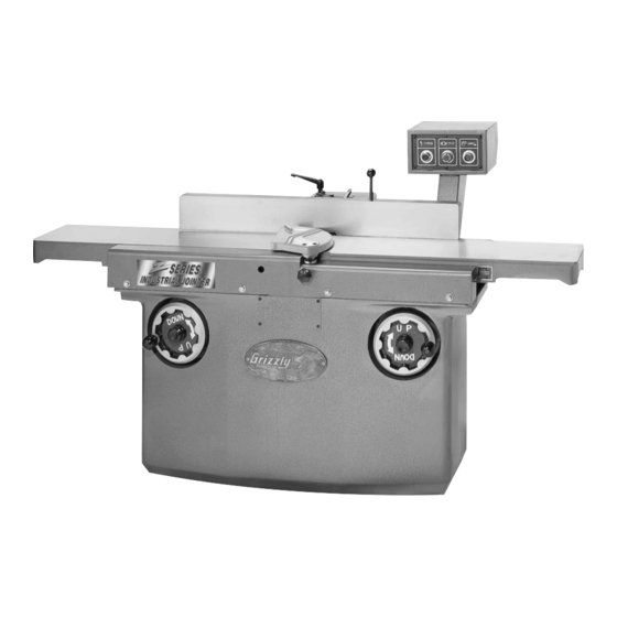
SECTION 3: INTRODUCTION Commentary We are proud to offer the Ultimate Series Jointers. These machines are part of a growing Grizzly family of fine woodworking machinery. When used according to the guidelines set forth in this manual, you can expect years of trouble-free, enjoyable operation and proof of Grizzly’s com-... -
Page 10: Comparison Chart And Terms
The fence is adjustable from 45° to 90° to the infeed and outfeed tables. Adjustment Handwheels: Controls the height of the infeed and outfeed tables. Ultimate Series Jointers G9859 G9860 G9860ZX ⁄ " x 73 ⁄... -
Page 11: Unpacking
Unpacking The Ultimate Series Jointers are shipped from the manufacturer in a carefully packed carton. If you discover the machine is damaged after you’ve signed for delivery, immediately call Customer Service for advice. When you are completely satisfied with the con- dition of your shipment, you should inventory its parts. -
Page 12: Clean Up
Remove this protective coating with a solvent cleaner or citrus-based degreaser such as Grizzly’s G7895 Degreaser. Avoid chlorine-based solvents as they may damage painted surfaces should they come in contact. Always follow the usage instructions on the product you choose for clean up. -
Page 13: Assembly
Beginning Assembly Disconnect power to the machine when perform- ing any maintenance, assembly ments. Failure to do this may result in serious personal injury. Keep rolled up and out of the way of machinery and keep hair pulled back. Wear during the entire assem- bly process. -
Page 14: Cutterhead
Installed Key Figure 4. Properly installed key. 3. Carefully lift the fence assembly onto the fence base support. Make sure that the key is fully seated into the key way. Avoid letting the fence slide across the jointer tables. 4. Slide the lock handle shaft through the flat washer and into the slot on the top of the fence assembly base. -
Page 15: Pedestal Switch
Pedestal Switch Your jointer comes with a pedestal mounted mag- netic switch for safety and convenience. Simply bolt the pedestal to the four mounting holes on the back side of the stand with (4) M10-1.5 x 25 cap screws and (4) M10 flat washers as shown in Figure 7A &... -
Page 16: Adjustments
Table Lock Serious personal injury may occur. -14- The Model G9953 is supplied with a 4 knife cutterhead, while the Models G9859/60/61 have 3 knife cutterheads. adjust- Jointer knives are extremely sharp. Never grab the cutterhead directly to rotate it. -
Page 17: Knives
Brake Rod Figure 8. Engaging the brake rod. Knife Setting Gauge Outfeed Table Figure 9 shows the setting of the knives with the knife setting gauge. The knives are locked into the cutterhead with wedge-type gibs and gib bolts. Jack screws under the knives allow fine tuning to help in the setting process. -
Page 18: Spiral Cutterhead
Each edge of the indexed cutter is marked for easy identification. When an indexed cutter needs to be replaced, please order part #H2334 from the current Grizzly catalog. Outfeed Table Facing the fence, the outfeed table is located to the left of the cutterhead. -
Page 19: Infeed Table
Infeed Table To adjust the infeed table: 1. The infeed table can be adjusted the same way as the outfeed table. Loosen the infeed table lock knob in the center of the handwheel. 2. Place a straightedge on the outfeed table so it hangs over the infeed table. -
Page 20: Fence Stop
45° Fence Stop Place a 45° gauge on the outfeed table fair- ly close to the cutterhead as shown in Figure Figure 16. Using a 45° gauge to align fence. While holding the fence adjusting handle, loosen the angle setting lock knob and the checknut on the 45°... -
Page 21: Operations
SECTION 6: OPERATIONS Test Run Disconnect power to the machine when perform- ing any maintenance, assembly ments. Failure to do this may result in serious personal injury. Keep loose rolled up and out of the way of machinery and keep hair pulled back. Wear during the entire opera- tion process. -
Page 22: Edge Jointing
Edge Jointing The purpose of edge jointing is to produce a fin- ished, flat-edged surface that is suitable for join- ery or finishing. Jointing is also a necessary step prior to ripping stock to width on a table saw or radial arm saw. -
Page 23: Surface Planing
Surface Planing The purpose of planing on a jointer is to produce one flat surface. The theory behind this is that once you have one flat surface on a board, the board can then more readily be milled to precise, flat dimensions on a thickness planer. -
Page 24: General
Disconnect power to the machine when perform- assembly ments. Failure to do this may result in serious per- sonal injury. Keep loose rolled up and out of the way of machinery and keep hair pulled back. Wear safety glasses dur- ing the entire mainte- nance process. -
Page 25: Closure
Ultimate Series Jointers We recommend you keep a copy of our current catalog for complete information regarding Grizzly's warranty and return policy. If you need additional technical information relating to this machine, or if you need general assistance or replacement parts, please contact the Service Department listed in Section 3 Introduction. -
Page 26: Troubleshooting Guide
TROUBLESHOOTING SYMPTOM POSSIBLE CAUSE Motor will not start. Low voltage. Open circuit in motor or loose connections. Motor will not start; fuses or Short circuit in line cord or plug. circuit breakers blow. Short circuit in motor or loose connections. Incorrect fuses or circuit break- ers in power line. -
Page 27: Machine Data, Parts Breakdown And Parts Lists
Customer Service #: (570) 546-9663 • To Order Call: (800) 523-4777 • Fax #: (800) 438-5901 8" JOINTER MODEL G9859 Design Type ...Floor Model Overall Dimensions: Table Size ...73 Height (from Floor to Table) ...30 Overall Length ...73 Overall Width...31'' Fence ...4... - Page 28 G9859 8" JOINTER...
- Page 29 G9859 8" JOINTER...
- Page 30 G9859 8" JOINTER...
- Page 31 G9859 8" JOINTER...
- Page 32 G9859 8" JOINTER...
- Page 33 Ref# Part# Description 001 P9859001 BASE 002 P9859002 FENCE SEAT 003 P9859003 TABLE SUPPORT 004 P9859004 TABLE LIFTING ARM 005 P9859005 TABLE SUPPORT 006 P9859006 FRONT HOUSING 007 P9859007 RIGHT REAR HOUSING 008 P9859008 LEFT REAR HOUSING 009 P9859009 TABLE HEIGHT SPINDLE 010 P9859010 TABLE LIFTING ARM 011 P9859011...
- Page 34 Ref# Part# Description 509 P9859509 SPECIAL RETAINER RING 510 P9859510 SPECIAL WASHER 511 P9859511 LOCK KNOB 512 P9859512 HANDWHEEL KNOB 513 PSB47M CAP SCREW M10-1.5 X 40 514 PN03M HEX NUT M8-1.25 515 PSS04M SET SCREW M6-1.0 X 12 516 P9859516 LUBE FITTING 517 PK20M KEY 5 X 5 X 15...
- Page 35 Customer Service #: (570) 546-9663 • To Order Call: (800) 523-4777 • Fax #: (800) 438-5901 12" JOINTER MODEL G9860/G9860ZX Design Type ...Floor Model Overall Dimensions: Table Size ...80'' x 12 Height (from Floor to Table) ...30 Overall Length ...80'' Overall Width...34 Fence ...4 Shipping Weight ...1265 lbs.
- Page 36 G9860 12" JOINTER...
- Page 37 G9860 12" JOINTER...
- Page 38 G9860 12" JOINTER...
- Page 39 G9860 12" JOINTER...
- Page 40 G9860 12" JOINTER...
- Page 41 Ref# Part# Description 001 P9860001 BASE 002 P9860002 FENCE SEAT 003 P9859003 TABLE SUPPORT 004 P9859004 TABLE LIFTING ARM 005 P9859005 TABLE SUPPORT 006 P9859006 FRONT HOUSING 007 P9859007 RIGHT REAR HOUSING 008 P9859008 LEFT REAR HOUSING 009 P9860009 TABLE HEIGHT SPINDLE 010 P9859010 TABLE LIFTING ARM 011 P9859011...
- Page 42 Ref# Part# Description 507 P9859507 LIFT ROD 508 P9859508 SPECIAL RETAINER RING 509 P9859509 SPECIAL RETAINER RING 510 P9859510 SPECIAL WASHER 511 P9859511 LOCK KNOB 512 P9859512 HANDWHEEL KNOB 513 PSB47M CAP SCREW M10-1.5 X 40 514 PN03M HEX NUT M8-1.25 515 PSS04M SET SCREW M6-1.0 X 12 516 P9859516...
- Page 43 Customer Service #: (570) 546-9663 • To Order Call: (800) 523-4777 • Fax #: (800) 438-5901 14" JOINTER MODEL G9861 Design Type ...Floor Model Overall Dimensions: Table Size ...79 Height (from Floor to Table) ...30 Overall Length ...80'' Overall Width...36'' Fence ...4 Shipping Weight ...1210 lbs.
- Page 44 G9861 14" JOINTER...
- Page 45 G9861 14" JOINTER...
- Page 46 G9861 14" JOINTER...
- Page 47 G9861 14" JOINTER...
- Page 48 G9861 14" JOINTER...
- Page 49 Ref# Part# Description 001 P9861001 BASE 002 P9861002 FENCE SEAT 003 P9859003 TABLE SUPPORT 004 P9859005 TABLE SUPPORT 005 P9859011 BASE COVER 006 P9861006 TABLE SPINDLE 007 P9859006 FRONT HOUSING 008 P9859008 LEFT REAR HOUSING 009 P9859007 RIGHT REAR HOUSING 010 P9859012 SWITCH BOX 011 P9859013...
- Page 50 Ref# Part# Description 503 P9859503 GEAR 504 P9859504 COLLAR 505 P9859505 LIFT ROD 506 P9859506 GEAR 507 P9859507 LIFT ROD 508 P9859508 SPECIAL RETAINER RING 509 P9859509 SPECIAL RETAINER RING 510 P9859510 SPECIAL WASHER 511 P9859511 LOCK KNOB 512 P9859512 HANDWHEEL KNOB 513 PB32M HEX BOLT M10-1.5 X 25...
- Page 51 NOTES Ultimate Series Jointers -49-...
-
Page 52: Warranty And Returns
WARRANTY AND RETURNS Grizzly Industrial, Inc. warrants every product it sells for a period of 1 year to the original purchaser from the date of purchase. This warranty does not apply to defects due directly or indirectly to misuse, abuse, negligence, accidents, repairs or alterations or lack of maintenance. - Page 53 Do you think your purchase represents good value? ___Yes Would you recommend Grizzly Industrial to a friend? ___Yes Would you allow us to use your name as a reference for Grizzly customers in your area? Note: We never use names more than three times. ___Yes Comments:_________________________________________________...
- Page 54 FOLD ALONG DOTTED LINE FOLD ALONG DOTTED LINE Send a Grizzly Catalog to a friend: Name_______________________________ Street_______________________________ City______________State______Zip______ GRIZZLY INDUSTRIAL, INC. P.O. BOX 2069 BELLINGHAM, WA 98227-2069 TAPE ALONG EDGES--PLEASE DO NOT STAPLE Place Stamp Here...