Chauvet Intimidator Spot LED 150 User Manual
Green thinking intimidator spot led 150
Hide thumbs
Also See for Intimidator Spot LED 150:
- Quick reference manual (61 pages) ,
- User manual (26 pages) ,
- Quick reference manual (9 pages)
Table of Contents
Advertisement
Quick Links
Advertisement
Table of Contents

Related Manuals for Chauvet Intimidator Spot LED 150


Summary of Contents for Chauvet Intimidator Spot LED 150
- Page 1 User Manual...
-
Page 2: Table Of Contents
Document Information The information and specifications contained in this document are subject to change without notice. CHAUVET® assumes no responsibility or liability for any errors or omissions that may appear in this manual. © Copyright 2011 CHAUVET®. All rights reserved Printed in P.R.C. -
Page 3: Before You Begin
1. B EFORE EGIN What Is Included · 1 x Intimidator™ Spot LED 150 · 1 x Mounting Bracket · 2 x Mounting Bolts · 1 x Safety Eyebolt · 1 x Power Cord · 1 x Warranty Card · 1 x User Manual Unpacking Instructions Immediately upon receiving this product, carefully unpack it and check the container in... -
Page 4: Safety Notes
Safety Notes Please read the following notes carefully because they include important safety information about the installation, usage, and maintenance of this product. · Keep this User Manual for future consultation. If you sell this product to another user, be sure that they also receive this document. ·... -
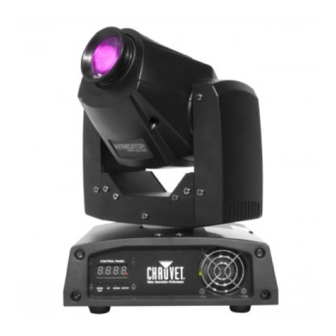
Page 5: Introduction
2. I NTRODUCTION Product Overview Power in DMX out DMX in Power out Fuseholder Intimidator™ Spot LED 150 User Manual (Rev. 4) Page 5 of 18... -
Page 6: Product Dimensions
Product Dimensions Page 6 of 18 Intimidator™ Spot LED 150 User Manual (Rev. 4) -
Page 7: Setup
The power linking diagram shown above corresponds to the North American version of this product ONLY! If using this product in other markets, you must consult with the local CHAUVET® distributor as power linking connectors and requirements may differ in your country or region. -
Page 8: Mounting
Mounting Orientation The Intimidator™ Spot LED 150 may be mounted in any position, provided there is adequate room for ventilation around it. Rigging Be sure that the structure onto which you are mounting this product can support its weight. Please see the “Technical Specifications” section of this manual for weight information. -
Page 9: Operation
4. O PERATION Control Panel Operation To access the control panel functions, use the four buttons located underneath the display. Button Function Press to find an operation mode or to <MODE/ESC> back out of the current menu option Press to scroll down the list of options <UP>... -
Page 10: Menu Map (Hidden)
Menu Map (hidden) This fixture has a hidden menu. The purpose of this menu is to adjust the home position (electronic adjustment) of the attributes listed below. Mode Programming Steps Description Pan adjustment P*** P000~255 Adjust the pan home position Tilt adjustment t*** t000~255... -
Page 11: Configuration (Dmx)
Configuration (DMX) Set this product in DMX mode to control it with a DMX controller. 1) Connect this product to a suitable power outlet. 2) Turn this product on. 3) Connect a DMX cable from the DMX output of the DMX controller to the DMX input socket of this product. - Page 12 Master/Slave Mode This mode allows a single Intimidator™ Spot LED 150 unit (the “master”) to control the actions of one or more Intimidator™ Spot LED 150 units (the “slaves”) without the need of a DMX controller. The master unit will be set to operate in either Automatic or Sound Active mode, while the slave units will be set to operate in Slave Mode.
-
Page 13: Dmx Channel Assignments And Values
DMX Channel Assignments and Values 11-CH Channel Function Value Setting 000 ó 255 0~540° 000 ó 255 Tilt 0~270° 000 ó 255 Pan fine 0~3° 000 ó 255 Tilt fine 0~3° 000 ó 255 Pan/tilt speed Fast~slow 000 ó 005 Open (white) 006 ó... - Page 14 Continued from previous page Channel Function Value Setting 072 ó 087 Automatic movement 5 088 ó 103 Automatic movement 6 104 ó 119 Automatic movement 7 120 ó 135 Automatic movement 8 136 ó 151 Sound-active movement 1 152 ó 167 Sound-active movement 2 Pan/tilt Movement macros 168 ó...
-
Page 15: Technical Information
5. T ECHNICAL NFORMATION General Maintenance Dust build up reduces light output performance and can cause overheating. This can lead to reduction of the light source’s life and/or mechanical wear. To maintain optimum performance and minimize wear, you should clean your lighting fixtures at least twice a month. -
Page 16: General Troubleshooting
#32 Terminator not connected Install a terminator, as indicated in the “DMX Primer” section. If you still experience problems after trying the above solutions, contact CHAUVET® Technical Support. Page 16 of 18 Intimidator™ Spot LED 150 User Manual (Rev. 4) -
Page 17: Returns Procedure
Be prepared to provide the model number, serial number, and a brief description of the cause for the return. The user must clearly label the package with an RMA #. CHAUVET® will refuse any product returned without an RMA #. -
Page 18: Technical Specifications
6. T ECHNICAL PECIFICATIONS Length Width Height Weight Dimensions and Weight 8.1 in (205 mm) 8.3 in (211 mm) 11.5 in (291 mm) 9.3 lbs (4.2 kg) Note: Dimensions in inches rounded to the nearest decimal digit. Power Power Supply Type Range Voltage Selection Switching (internal)