
Related Manuals for Alto MAXIDRIVE3.4 COMPACT


Summary of Contents for Alto MAXIDRIVE3.4 COMPACT
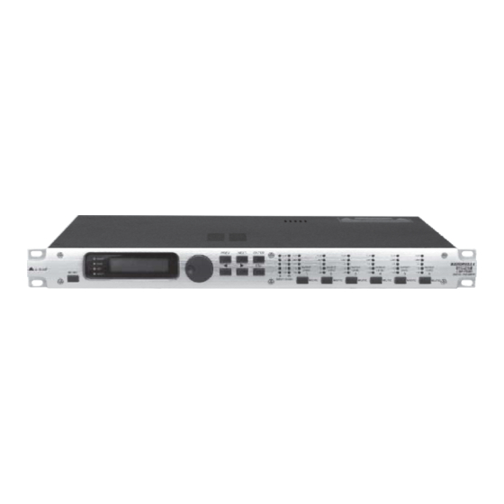
- Page 1 User's Manual MAXIDRIVE3.4 3 WAY STEREO COMPACT DIGITAL CROSSOVER www.altoproaudio.com Version 1.2 August. 2005 English...
- Page 2 Fuse SAFETY RELATED SYMBOLS To prevent fire and damage to the product, use only the recommended fuse type as indicated in this CAUTION manual. Do not short-circuit the fuse holder. Before RISK OF ELECTRIC SHOCK DO NOT OPEN replacing the fuse, make sure that the product is OFF and disconnected from the AC outlet.
- Page 3 PREFACE Dear Customer: Thanks for choosing MAXIDRIVE3.4 COMPACT 3 - Way Stereo Digital Crossover and thanks for choosing one of the results of LTO AUDIO TEAM job and researches. For our LTO AUDIO TEAM, music and sound are more than a job...are first of all passion and let us say our obsession! We have been designing professional audio products for a long time in cooperation with some of the major brands in the world in the audio field.
-
Page 4: Table Of Contents
TABLE OF CONTENTS 1. INTRODUCTION ........................... 4 2. FEATURES .............................4 3. CONTROL ELEMENTS .........................4 3.1 The Front Panel 3.2 The Rear Panel 4. GETTING STARTED ..........................4.1 Configuration of The System 4.2 Adjust The Input Signal 4.3 First Setup 4.4 System Configuration 4.5 Number of Presets 4.6 Type of Preset... -
Page 5: Introduction
1. INTRODUCTION Your MAXIDRIVE3.4 COMPACT is a 3-Way Stereo Digital Crossover and it is a powerful versatile signal processor. The apparatus will provide 3, 4, 5 or 6-way mono X-over with 6 outputs. Thanks to the use of selected and expensive components, the performances of MAXIDRIVE3.4 COMPACT are worth much more than its price: you can set the... -
Page 6: The Rear Panel
INPUT A 12.AC inlet and fuse holder Use it to connect your MAXIDRIVE3.4 COMPACT to the supplied AC cord. Please check the Voltage in your country and what voltage for your MAXIDRIVE3.4 COMPACT is configured before attempting to connect the unit for the main AC. -
Page 7: Getting Started
At first, switch off the equipment, carry out the audio and power connection from the various components of your sound system. Then, connect the main cord and only switch on the MAXIDRIVE3.4 COMPACT. The display will show the data regarding with the operating system release for a few seconds. -
Page 8: Adjust The Input Signal
Keep the MAXIDRIVE3.4 COMPACT outputs in MUTE status (LEDs light on). Feed a signal in on the MAXIDRIVE3.4 COMPACT's input and watch the INPUT LEVEL A-B LED ladders. To obtain a good signal/noise ratio, i.e. an up-front distortion-free signal, keep the signal quite high, but make certain the red CLIP LED doesn't light up continually. -
Page 9: First Setup
Output Delay Alignment of the speaker enclosure components Output Gain Levels of the outputs Note: The regulation of the MAXIDRIVE3.4 COMPACT's parameters is closely related to the characteristics of the components of the sound system. So if you're not the expert, please refer to the documentation and technical specifications of your power amplifiers, loudspeaker enclosures, monitors, etc.. -
Page 10: Number Of Presets
of the signal on inputs is assigned to outputs and . The system is therefore configured as shown in the following diagram. 2-WAY STEREO + 2 MONO AUX (2X2W + 2MAX) A13 B24 S56 LEFT HIGH LEFT HIGH RIGHT LOW LEFT LOW RIGHT MONO AUX L +R RIGHT... -
Page 11: Preset Modifications
4.8 PRESET Modifications A 1 3 B 2 4 S 5 6 2 x 2 W + 2 M A X This indicates that the value of one or more parameters has been temporarily modified with respect to the stored in the PRESET shown. - Page 12 1, 3 and 5; Input B signal assigned to outputs 2, 4 and 6. Loading a PRESET, a PRESET Change command is also automatically sent to the serial ports and can be used to automatically load a PRESET with the same number to any other MAXIDRIVE3.4 COMPACT units connected and enabled (Refer to...
- Page 13 2 W + 2 M A X 5.1.3 Dump Out PRESET Use this menu page to download a PRESET via the serial ports. It is also used to immediately "copy" the settings of the various PRESETS of a MAXIDRIVE3.4 COMPACT to another MAXIDRIVE3.4 COMPACT.
- Page 14 PRESET sent by the transmitting MAXI- DRIVE3.4 COMPACT (TX) overwrites (and therefore cancels) the existing PRESET in the same memory position of the receiving MAXIDRIVE3.4 COMPACT (RX). MAXIDRIVE3.4 COMPACT #1 MAXIDRIVE3.4 COMPACT #2 MAXIDRIVE3.4 COMPACT #3 Incoming Dump Incoming Dump Incoming Dump...
-
Page 15: Delay Menu
5.2.Delay Menu Use this menu to work on the systems delay lines. menu Input Delay Parameters DELAY Output Delay Parameters Parameters In these pages, the number of the parameters and how they are presented varies according to the configuration of the PRESET and according to Ganging Units settings (... - Page 16 5.2.1 Input Delay Use this menu page to adjust the delay lines of Input A, Input B and SUM. I n p u t D e l a y IN A The values can be set in the following ranges: INPUT DELAY I N A D E L A Y...
-
Page 17: Edit Menu
The values can be set in the following ranges: OUTPUT DELAY 0 P 1 D E L A Y 2 9 2 u S unit range step 0.0 ~ 100.0 0 ~ 100000 0 ~ 291 0 ~ 291271 The values can be set in the following ranges: OUTPUT DELAY OUTPUT DELAY OUTPUT DELAY... - Page 18 5.3.1 Input Gain Input gain control. I n p u t G a i n Allows to adjust the amplification of the signal fed in through Inputs A and B. Editing values are in the range +6dB ~ -30dB, with 0.5dB steps. I N A G A I N - 2 .
- Page 19 Each equalizer has 5 pages (one for each filter), showing the name of the input it affects and the number of the filter. I N A E Q 1 1 . 0 - 5 . 0 The following editable parameters are available for each filter: a.
- Page 20 Peaking Notch d. Gain Allows to control the boost or cut of the selected frequencies. It's not used with the Notch Filter, which has a fixed cut. I N A E Q 1 1 . 0 - 5 . 0 Peaking Low Shelving High Shelving...
- Page 21 Each Xover has 2 slightly different pages (one for each filter), where the name of the output it affects and the type of filter are shown. L P F h r u H P F h r u O P 1 1 k 0 0 H z 1 k 0 0 H z Output 1 - Low Pass Filter...
- Page 22 Phase Allows fine control (in 5 steps) of the signal's phase. The effect of this control is summed with that of the Output Polarity function (0 ~ 180 ). In this way it's possible to adjust the phase of each individual output with 5 steps through a full 360 . Note: this control is only in the Low-Pass Filter window.
- Page 23 5.3.6 Output Gain Output level control Allows to adjust the signal level of each individual output. O u t p u t G a i n Editing values are between +6dB ~ -30dB, with 0.5dB steps. O P 1 G A I N - 6 .
-
Page 24: Utility Menu
b. Reaction times Allows to choose between 3 types of Limiter reaction speed. In fact, these are attack and release times that are optimised so that the Limiter reacts more or less rapidly when the signal exceeds or drops below the threshold: Fast short times, suited to rapid Limiter operation. - Page 25 PRESET Change RX Allows to accept or ignore the PRESET Change command sent via the serial ports from a computer or another MAXIDRIVE3.4 COMPACT when it loads a PRESET. The settings can be: Ignore PRESET Change commands received. Accept and execute PRESET Change commands.
- Page 26 PRESET with the corresponding number. This means that, in a chain of MAXIDRIVE3.4 COMPACT, all the units set with PRESET Change RX = Accept load the same number of PRESET, in spite of the fact that it corresponds to PRESETS with different contents in the various units.
- Page 27 IMPORTANT: Precisely for its characteristics, the Ganging function affects the way in which the relative para- meters audio are edited or represented: As soon as Inputs and/or Outputs are ganged, the various menu pages only show the values that can actually be used.
- Page 28 5.4.3 UNITS SUBMENU Units Delay Unit Lim. Thresh. Unit Temperature Unit Used this submenu to choose the measurement units to be used with certain functions. U n i t s a. Delay Unit Used to set the measurement units in which Delays are expressed (DELAY menu). The options include: meters - mm =...
- Page 29 Note: the measurement units can be chosen between C (degrees Centigrade) and F (degrees Fahrenheit) by means of the Temperature Unit function (UTILITY menu - Units submenu). d. Wake Up Allows to choose the mode in which MUTE functions are restored when the MAXIDRIVE3.4 COMPACT is switched on. The options include: Normal...
- Page 30 e. LCD Contrast Allows to adjust the Display contrast. The values are in the following range: 0 (minimum contrast) ~ 32 (maximum contrast). L C D C o n t r a s t 5.4.5 LOCK SUBMENU Used to enable or disable the protection of the system against accidental or unauthorized changes. Lock Lock L o c k...
- Page 31 L O C K L O C K P a s s w o r d P a s s w o r d [ 1 2 3 4 ] [ B I R D ] After entering the password, press ENTER. Note: Confirmation is only accepted if the cursor is positioned on one of the passwords four characters.
-
Page 32: Connections
6. CONNECTIONS The following diagrams show the schemes of the recommended cables and some connection examples referred to various system configurations. Inputs A & B, RS485 IN GROUND BALANCED XLR-M HOT (+) COLD ( ) Inputs A & B SLEEVE GROUND BALANCED JACK RING... -
Page 33: Application
7. APPLICATION The following diagrams show the MAXIDRIVE3.4 COMPACT's various system configurations, as if to say, the various input and output hardware combinations. 7.1.Factory Preset Configuration Name Configuration Configuration DEFAULT A135 B246 Default preset - routing = 3-WAY STEREO A13 B24 S56... -
Page 34: Organization
95-240V 50/60Hz jordat uttag nar den ansluts PUSH OUTPUTS till ett natverk FUSE: 95-120V T500mAL 210-240V T315mAL TIDE TIDE TIDE A102 RS485 OUT RS485 IN RS232 INPUT B INPUT A MAXIDRIVE3.4 COMPACT 3-WAY STEREO DIGITAL CROSSOVER AUDIO MIXER SIGNAL POWER... - Page 35 95-240V 50/60Hz PUSH OUTPUTS till ett natverk FUSE: 95-120V T500mAL 210-240V T315mAL TIDE TIDE TIDE A102 RS485 OUT RS485 IN RS232 INPUT B INPUT A MAXIDRIVE3.4 COMPACT 3-WAY STEREO DIGITAL CROSSOVER AUDIO MIXER SIGNAL POWER...
- Page 36 PUSH 95-240V 50/60Hz OUTPUTS till ett natverk FUSE: 95-120V T500mAL 210-240V T315mAL TIDE TIDE TIDE A102 RS485 OUT RS485 IN RS232 INPUT B INPUT A MAXIDRIVE3.4 COMPACT 3-WAY STEREO DIGITAL CROSSOVER AUDIO MIXER SIGNAL POWER...
- Page 37 95-240V 50/60Hz jordat uttag nar den ansluts PUSH OUTPUTS till ett natverk FUSE: 95-120V T500mAL 210-240V T315mAL TIDE TIDE TIDE A102 RS485 OUT RS485 IN RS232 INPUT B INPUT A MAXIDRIVE3.4 COMPACT 3-WAY STEREO DIGITAL CROSSOVER SIGNAL POWER AUDIO MIXER...
- Page 38 Communications: PC & one or more MAXIDRIVE3.4 COMPACT connection to / from RS232 Serial Port MAXIDRIVE3.4 COMPACT 3-WAY STEREO to / from DIGITAL CROSSOVER RS232 AC INPUT Apparaten skall anslutas till PUSH PUSH 95-240V 50/60Hz jordat uttag nar den ansluts...
-
Page 39: Technical Specifications
8. TECHNICAL SPECIFICATIONS INPUT section Connectors 2 x COMBO Nominal input sensitivity 0 dB (0.775 V) Input Impedance 30kOhm, electronically balanced Maximum Input Level +20dBu Input Gain -30 / +6 dB variable in 0.5 dB steps Output Section Connectors 6 x XLR-M Output Impedance 600 Ohms, electronically balanced Nominal Output Level... -
Page 40: Warranty
9. WARRANTY 1. WARRANTY REGISTRATION CARD To obtain Warranty Service, the buyer should first fill out and return the enclosed Warranty Registration Card within 10 days of the Purchase Date. All the information presented in this Warranty Registration Card gives the manufacturer a better understanding of the sales status, so as to purport a more effective and efficient after-sales warranty service. - Page 41 No. 1, Lane 17, Sec. 2, Han Shi West Road, Taichung 40151, Taiwan http://www.altoproaudio.com Tel: 886-4-22313737 email: alto@altoproaudio.com Fax: 886-4-22346757 All rights reserved to ALTO. All features and content might be changed without prior notice. Any photocopy, translation, or reproduction of part of this manual without written permission is forbidden. Copyright...