
Related Manuals for HAMPTON BAY Windward IV


Summary of Contents for HAMPTON BAY Windward IV
- Page 1 Windward IV Ceiling Fan Owner’s Manual Windward IV Ventilador de Techo de 1.32 Manual del Propietario E00000...
-
Page 2: Table Of Contents
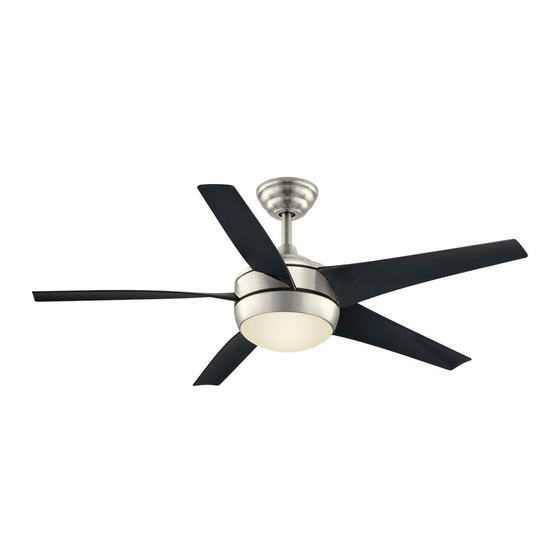
52” Windward IV Thank you for purchasing this Hampton Bay ceiling fan. This product has been manufactured with the highest standards of safety and quality. The finish Ceiling Fan by Hampton Bay of this fan is weather resistant, but over time will naturally weather and fade. -
Page 3: Safety Rules 1
READ AND SAVE THESE INSTRUCTIONS Do not wait for the fan to stop to press the reverse button. To reduce the risk of electric shock, insure electricity The fan will not reverse if the fan is not moving. has been turned off at the circuit breaker or fuse box before beginning. -
Page 4: Parts
Unpack your fan and check the contents. You should have the following items: Blade Attachment Hardware 1. Slide-On Mounting Plate (inside Canopy) 7. Glass Shade (16 Screws) 2. Downrod and Ball Assembly 8. Bulbs (2) Electrical Hardware 3. Canopy with Canopy Ring Attached 9. -
Page 5: Mounting
WITH THE OUTLET BOX. OUTLET BOXES Figure 2 COMMONLY USED SUPPORT installation hanger bar as shown in Figure 4 LIGHTING FIXTURES (available at your Hampton Bay retailer). ACCEPTABLE SUPPORT MAY NEED TO BE REPLACED. CONSULT A Installing Your Fan 3. QUALIFIED ELECTRICIAN IF IN DOUBT. -
Page 6: Hanging The Fan
Hanging the Fan Once you have decided which ceiling Loosen but installation you will use, proceed with the Remove Do Not Remove REMEMBER turn pow- following instructions. Where necessary, er. Follow the steps below to hang your each section of the instructions will note the fan properly. -
Page 7: Close-To-Ceiling" Mounting
4. Remove three of the six screws and lock Tighten Set Mounting washers (every other one) securing the mo- Screws Screw tor collar to the top of the fan motor housing (Supplied With UL Listed (Figure 10). Outlet Box) Outlet Box 5. - Page 8 Installing Fan to Collar the Outlet Box Screw and Lockwasher (3 Screws) WHEN MOUNTING THE FAN ON A SLOPED Canopy CEILING, THE STANDARD BALL/DOWNROD Ceiling Ring MOUNTING METHOD MUST BE USED. THE Canopy MOUNTING PLATE MUST BE MOUNTED SO THAT THE SLOT OPENINGS ARE ON THE LOWER SIDE BY SLIDING THE MOUNTING PLATE FROM THE TOP DOWN.
-
Page 9: Electrical Connections
Making the Electrical 6. Connect the receiver white wire to the sup- SUPPLY CIRCUIT ply white wire (neutral) wire using a wire Connections nut (Figure 13). 7. After connecting the wires, spread them REMEMBER to disconnect the power. If apart so that the green and white wires are you feel you do not have enough electrical one side of the outlet box and the black wire wiring knowledge or experience, have your fan... - Page 10 Finishing the Fan and turn clockwise to lock in place. Imme- diately tighten the two mounting screws Installation firmly. Slot Cut-Off for 2. Install the remaining two mounting screws Blade lnsert STANDARD CEILING MOUNTING into the holes in the canopy and tighten firmly.
-
Page 11: Installing The Light Kit
ment. Repeat for each blade. Measurement Connect the white wire exiting the bottom deviations should within 1/8”. Run the fan of the fan motor assembly with the white for 10 minutes. wire from the top of the light kit fitter as- Black Bracket sembly (Figure 16). -
Page 12: Operating Your Fan
CAUTION - This device complies with part 15 of the FCC rules. Changes or modifications not DO NOT WAIT FOR THE FAN TO STOP TO PRESS expressly approved by the manufacturer could THE REVERSE BUTTON. THE FAN WILL NOT RE- void your authority to operate this equipment. -
Page 13: Setting The Code
Setting the Code on your control. To select your desired display in percentage number ranging from room temperature, press the button to dis- 100% to 20%. The light will cycle continu- This unit has 16 different code combinations. play FAN AUTO on the LCD display. ously between bright and dim setting as To set the code, perform the following steps: Use the TEMP./SET/HOUR BUTTONS... -
Page 14: Care Of Your Fan
Troubleshooting Care of Your Fan Here are some suggestions to help you Problem Solution maintain your fan. Fan will not start Check main and branch circuit fuses or breakers 1. Because of the fan’s natural movement, Check line wire connections to the fan and switch wire connections in some connections may become loose. -
Page 15: Specifications 13
FAN POWER AIRFLOW EFFICIENCY AIRFLOW CONSUMPTION GROSS CUBE FAN SIZE SPEED VOLTS (HIGHER IS BETTER) (WITHOUT WEIGHT WEIGHT FEET CFM/WATT LIGHTS) WATT 2448 20.2 23.8 52” 4289 1.82 High 6057 These are approximate measures. They do not include Amps and Wattage used by the light kit. Distributed by Your Other Warehouse LLC 12100 Little Cayman Dr. -
Page 16: Warranty Information
You must present a copy of the original Hampton Bay also warrants that all other fan parts, excluding any glass or acrylic blades, to be free purchase receipt to obtain warranty service. - Page 17 Windward IV de 52” Gracias por comprar este ventilador de techo de Hampton Bay. Este producto se ha fabricado con las normas de seguridad y calidad más altas. El acabado Ventilador de techo de Hampton Bay de este ventilador es resistente a la intemperie, pero con el tiempo, exhibirá...
-
Page 18: Normas De Seguridad 1
LEE LAS INSTRUCCIONES Y GUÁRDALAS Oprime el botón de reversa cuando el ventilador todavía está en Para disminuir el riesgo de descarga eléctrica, asegúrate de que la movimiento. Si el ventilador no está en movimiento no cambiará electricidad ha sido apagada en el cortacircuitos o la caja de fusibles de dirección. -
Page 19: Cómo Desempacar El Ventilador
Desempaca tu ventilador y revisa el contenido. Deberá tener las siguientes piezas: Herrajes de montaje de aspas 1. Placa de montaje deslizante (dentro de la 6. Ensamblado del soporte del kit de luces (16 tornillos) cubierta) 7. Pantalla de vidrio Herrajes eléctricos 2. -
Page 20: Cómo Instalar El Ventilador 3
SERVIR COMO SOPORTE DE VENTILADOR, Y muestra en la Figura 4 (disponible en la tienda Figura 2 TAL VEZ DEBAN REEMPLAZARSE. EN CASO minorista local de Hampton Bay). DE DUDA, CONSULTA A UN ELECTRICISTA Cómo instalar el ventilador 3. CALIFICADO. - Page 21 Cómo colgar el Una vez elegido el tipo de instalación, sigue Quitar Aflojar pero no retirar con las siguientes instrucciones. Cuando sea ventilador necesario, cada sección de las instrucciones indicará los diferentes procedimientos a seguir RECUERDA desconectar corriente. para los dos tipos de instalación. Sigue estos pasos para colgar correctamente tu ventilador.
- Page 22 4. Retira tres de los seis tornillos y arandelas Ajustar de seguridad (alternados) que sujetan el Tornillos de los tornillos montaje collarín del motor a la parte superior de la (incluidos con carcasa del motor (Figura 10). la caja eléctrica) Caja eléctrica 5.
- Page 23 Cómo instalar el Montaje Montaje ventilador en la caja Collarín “Cerca del Techo” estándar Tornillo y arandela de eléctrica seguridad (3 tornillos) Aro de Cubierta CUANDO MONTES EL VENTILADOR EN UN TECHO la cubierta de techo INCLINADO, DEBES USAR EL MÉTODO DE MONTAJE CON TUBO BAJANTE Y BOLA ESTÁNDAR.
- Page 24 Cómo hacer las 6. Conecta el cable blanco del receptor al CIRCUITO DE SUMINISTRO cable blanco de energía (neutro) usando una conexiones eléctricas tuerca de cable (Figura 13). 7. Después de conectar los cables, sepáralos RECUERDA desconectar la electricidad. de manera que los cables verde y blanco Si crees que no tienes suficiente experiencia queden de un lado de la caja eléctrica y el o conocimientos en cableado eléctrico, contrata...
- Page 25 Finalizar la instalación tornillos de la placa de montaje. Alza para enganchar las ranuras y gira de izquierda a del ventilador derecha para asegurar en su sitio. Ajusta con Ranura para firmeza los dos tornillos de montaje. insertar el aspa MONTAJE DE TECHO ESTÁNDAR 2.
- Page 26 su medición. Repite para cada aspa. Las cable negro del ensamblado del soporte del kit desviaciones de la medición deben estar de luces. Conecta el cable blanco que sobresale dentro de 1/8”. Enciende el ventilador por por debajo del ensamblado del motor del Soporte negro 10 minutos.
-
Page 27: Cómo Operar El Ventilador
PRECAUCIÓN - Este dispositivo cumple la Parte 15 de las reglas de la FCC. Cambios o OPRIME EL BOTÓN DE REVERSA CUANDO EL modificaciones no autorizadas expresamente VENTILADOR TODAVÍA ESTÁ EN MOVIMIENTO. SI EL por el fabricante pueden invalidar tu derecho VENTILADOR NO ESTÁ... - Page 28 temperatura configurada por ti. Sigue los manera; Oprime y suelta el botón y la luz se g. LUZ - Retardo - Oprimir este botón activa la siguientes pasos para configurar la temperatura encenderá o apagará. Oprime el botón sin función de retardo de la luz en tu control.
-
Page 29: Cuidado Del Ventilador
Solución de problemas Cuidado del ventilador Problema Solución Aquí tienes algunas sugerencias para el mantenimiento de tu ventilador. El ventilador no Verifica fusibles o disyuntores principales y secundarios. 1. Debido al movimiento natural del ventilador, enciende Verifica conexiones de cables en línea al ventilador y conexiones de cables algunas conexiones pueden... -
Page 30: Especificaciones 13
EFICIENCIA DEL FLUJO DE CONSUMO DE FLUJO DE AIRE AIRE PIES ENERGÍA (SIN PESO PESO PIES TAMAÑO VELOCIDAD VOLTIOS (MÁS ALTA MEJOR) CUB. X LAS LUCES) EN NETO BRUTO CÚB. PIES CÚB. X MIN./ MIN. VATIOS VATIOS Baja 2448 20.2 23.8 52”... -
Page 31: Información De La Garantía
Hampton Bay garantiza de por vida, a partir de la fecha de compra por el comprador original, que el motor del ventilador no presenta defectos de fabricación ni de material desde la fecha de salida de la Usted debe presentar una copia del fábrica.