Table of Contents
Advertisement
Quick Links
Advertisement
Table of Contents

Related Manuals for Chauvet Q-SPORT 560 LED


Summary of Contents for Chauvet Q-SPORT 560 LED
- Page 1 User Manual...
- Page 2 CHAUVET® to notify any person or company of such revision or changes. This does not constitute in any way a commitment by CHAUVET® to make such changes. CHAUVET® may issue a revision of this manual or a new edition of it to incorporate such changes.
-
Page 3: Table Of Contents
Table of Contents Table of Contents 1. Before You Begin ....................1 What Is Included ......................... 1 Unpacking Instructions ......................1 Claims ............................1 Typographic Conventions ....................1 Icon Meaning ........................2 Product at a Glance ......................2 ... - Page 4 Table of Contents 5. Technical Information ..................24 Product Maintenance ......................24 Troubleshooting Guide ...................... 25 Returns Procedure ......................26 Contact Us ........................26 Technical Specifications ....................27 -ii- Q-Spot™ 560-LED User Manual Rev. 06...
-
Page 5: Before You Begin
CHAUVET®,. Failure to do so in a timely manner may invalidate your claim with the carrier. In addition, keep the container and all the packing material for inspection. -
Page 6: Icon Meaning
Before You Begin Icon Meaning Icon Meaning This icon indicates critical installation, configuration, or operation information. Failure to comply with this information may render the product partially or completely inoperative, damage third-party equipment, or cause harm to you. This icon indicates important installation or configuration information. -
Page 7: Safety Notes
There are no user serviceable parts in this product. Any reference to servicing you find in this User Manual only applies to properly CHAUVET® certified technicians. Do not open the housing or attempt any repairs unless you are one of them. -
Page 8: Introduction
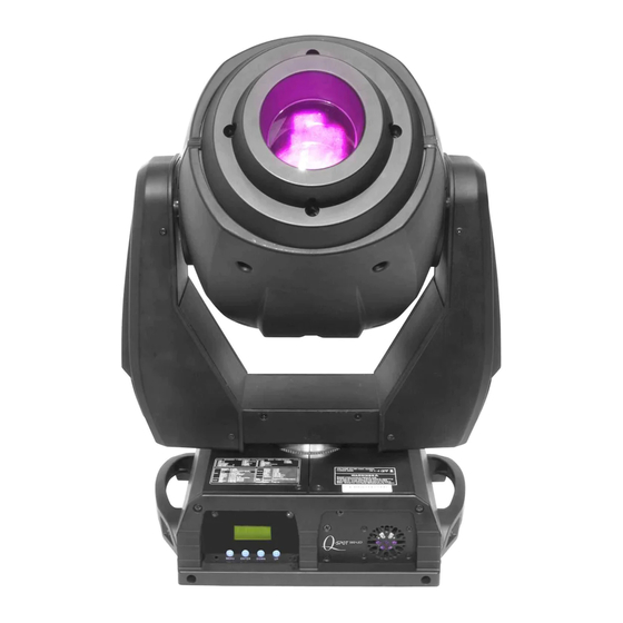
Introduction 2. Introduction Product The Q-Spot™ 560-LED is a high-power moving yoke product equipped with three (3) 60- watt white LEDs. This product includes a color wheel with seven slots, plus white, and two Description gobo wheels. One gobo wheel has seven fixed gobos, plus open. The other gobo wheel has six rotating slot-n-lock gobos, plus open. -
Page 9: Product Overview
Introduction Product Overview DMX In Power Switch Rear View DMX Out Control Panel Front View Q-Spot™ 560-LED User Manual Rev. 06... -
Page 10: Color Wheel
Introduction Color Wheel Gobo Wheel 1 Gobo Wheel 2 Q-Spot™ 560-LED User Manual Rev. 06... -
Page 11: Product Dimensions
Introduction Product Dimensions Q-Spot™ 560-LED User Manual Rev. 06... -
Page 12: Setup
The listed current rating indicates the maximum current draw during normal operation. For more information, you may download the document Sizing the Circuit Breakers from the CHAUVET® website: www.chauvetpro.com. Never connect this product to a rheostat (variable resistor) or dimmer circuit, even if the rheostat or dimmer channel serves only as a 0 to 100% switch. -
Page 13: Dmx Linking
If you are not familiar with the DMX standard, master/slave connectivity, or if you need information about the DMX cables needed to link this product to a DMX controller, you may download the document DMX Primer from the CHAUVET® website: www.chauvetpro.com. DO NOT connect a DMX controller to the products operating in Master/Slave mode. -
Page 14: Gobo Replacement
Setup 1. Turn the product off and disconnect from the power outlet. Gobo 2. Open the head cover by loosening the four fastening screws at the sides of the Replacement top cover. 3. Separate the gobo plate from the gobo wheel by pushing the gobo plate toward the front of the moving head (direction 1 in the diagram). -
Page 15: Mounting
Always mount this product in any safe position while making sure that there is adequate room for ventilation, configuration, and maintenance. Rigging CHAUVET® recommends following the general guidelines below when mounting this product. When selecting an installation location, consider easy access to this product for operation, programming adjustments, and routine maintenance. -
Page 16: Operation
Operation 4. Operation Control Panel Button Function Description Exits from the current menu or function <MENU> Enables the currently displayed menu or sets the currently selected <ENTER> value in to the current function Navigates upward through the menu list and increases the numeric <UP>... -
Page 17: Stand-Alone Operation
Operation 1. Go to MENU > INTRO > RUN. Stand-alone 2. Select a stand-alone operation mode (AUTO 1, AUTO 2, CUSTOM, Operation SOUND 1, SOUND 2, or TEST). Of all the stand-alone operation modes indicated above, only “CUSTOM” is editable (see Edit Custom). -
Page 18: Keylock
Operation Keylock Locks or unlocks the product’s display. 1. Go to MENU > INTRO > KEYLOCK. 2. Select YES or NO. When Keylock is in the “YES” setting, you will have to enter the password after 30 seconds of control panel inactivity or each time you turn the product on. The default (non-modifiable) password is <UP>, <DOWN>, <UP>, <DOWN>, and <ENTER>. -
Page 19: Fader Reversal
Operation Fader Reversal Define how the pan, tilt, and dimmer increase. 1. Go to MENU > INVERT > PAN. 2. Select a fader direction (NORMAL or REVERSE). 3. Go to MENU > INVERT > TILT. 4. Select a fader direction (NORMAL or REVERSE). 5. -
Page 20: Fan Wait
Operation Fan Wait Stop the fan during a blackout. 1. Go to MENU > SPECIAL > FAN_WAIT. 2. Select ON or OFF. System Default Default all product parameters to their default values. 1. Go to MENU > EXTRA. 2. Press <ENTER> (PASSWORD) will show on the display. 3. -
Page 21: Menu Map
Operation Menu Map Main Level Programming Levels Description Selects a starting DMX address INTRO ADDRESS 001~512 Resets the product’s custom settings RESET Selects DMX512-A running mode DMX512 Selects the first automatic program AUTO 1 Selects the second automatic program AUTO 2 SOUND 1 Selects the first sound activated program Selects the second sound program... - Page 22 Operation Main Level Programming Levels Description Selects the program step STEP EDIT Selects the pan position TILT Selects the tilt position SPEED Selects the pan/tilt speed Selects the color wheel position COLOR Selects the fixed gobo wheel position GOBO1 GOBO2 Selects the rotating gobo wheel position Selects the gobo rotation mode GOBO2ROT...
-
Page 23: Dmx Values
Operation DMX Values Basic Channel Function Value Percent/Setting 000 255 0~540° 000 255 0~270° Tilt 000 009 No Function 010 019 020 029 Green 030 039 Yellow 040 049 Blue 050 059 Orange 060 ... - Page 24 Operation Basic Channel Function Value Percent/Setting (Cont.) 000 009 No Function 010 039 Prism 040 049 Effect1 050 059 Effect2 060 069 Effect3 070 079 Effect4 080 089 Effect5 090 099 Effect6 100 ...
- Page 25 Operation Basic Channel Function Value Percent/Setting (Cont.) 000 019 Dim setting as set in product 020 039 Pan/tilt black activation 040 059 Pan/tilt black deactivation 060 139 No Function 140 149 Auto program 1 (3 s activation delay) 150 ...
- Page 26 Operation Advanced Channel Function Value Percent/Setting (Cont.) 000 010 No gobo 011 020 Gobo 1 021 030 Gobo 2 031 040 Gobo 3 041 050 Gobo 4 051 060 Gobo 5 061 070 Gobo 6 Gobo Wheel 2 071 ...
- Page 27 Operation 000 031 Close Advanced 032 063 Open (Cont.) 064 095 Strobe 0~20Hz 096 127 Open Strobe 128 159 Pulse Effect 160 191 Open 192 223 Random Effect 224 255 Open 000 019 Dim setting as set in product 020 ...
-
Page 28: Technical Information
Technical Information 5. Technical Information Product To maintain optimum performance and minimize wear, the user should clean this product frequently. Usage and environment are contributing factors in determining the cleaning Maintenance frequency. As a rule, you should clean this product at least twice a month. Dust build up reduces light output performance and can cause overheating. -
Page 29: Troubleshooting Guide
Send unit for repair Faulty Display/Main board Send unit for repair If you still experience technical problems after trying the above solutions or if you need to send the unit for repair, contact CHAUVET® Technical Support. Q-Spot™ 560-LED User Manual Rev. 06 -25-... -
Page 30: Returns Procedure
Be sure to pack the product properly. Any shipping damage resulting from inadequate packaging will be the customer’s responsibility. As a suggestion, proper FedEx packing or double-boxing is the method CHAUVET® recommends. CHAUVET® reserves the right to use its own discretion to repair or replace returned product(s). Contact Us World Headquarters United Kingdom &... -
Page 31: Technical Specifications
Technical Specifications Dimensions and Length Width Height Weight Weight 11.7 in (296 mm) 16.1 in (408 mm) 25.0 in (634 mm) 44.1 lbs (20.0 kg) Note: Dimensions in inches rounded to the nearest decimal digit. Power Supply Type Range Voltage Selection Electrical Switching (internal) 100~240 V, 50/60 Hz... - Page 32 CHAUVET® 5200 NW 108th Avenue Sunrise, FL 33351 (USA) (800) 762-1084 – (954) 929-1115 FAX (954) 929-5560 www.chauvetpro.com Q-Spot™ 560-LED User Manual Rev. 06 December 2011...