
Related Manuals for Pentair i-Link

Summary of Contents for Pentair i-Link
- Page 1 ™ IntelliTouch i-Link Protocol Interface Adapter User’s Guide IntelliTouch i-Link Protocol Interface Adapter User’s Guide...
- Page 2 Pentair Water Pool and Spa, Inc. Those names and brands may be the trademarks or registered trademarks of those parties or others.
-
Page 3: Table Of Contents
MODEL: IntelliTouch Model/Type ..............16 PUMPLO/PUMPHI: Pump Status (Two-speed Pumps Only) ......16 Testing IntelliTouch iLink via Hyper Terminal in Windows XP ...... 17 IntelliTouch i-Link Protocol Interface Adapter Installation ......18 Summary Information ..................18 Overview ....................... 19 Connection ....................19 IntelliTouch i-Link Adapter Location ............. -
Page 4: Intellitouch I-Link Adapter Software Commands
The default command character set displays after a start-up sequence. To display these characters power down/up or reset the IntelliTouch i-Link adapter. For the RST (reset) command information, see page 4. -
Page 5: General Command Response Formats
Operator and Value, the Value and ,<cr>. No space(s) is allowed between the Prefix and the Label. Examples: [Prefix][Label][Operator][Value]<cr> (valid) [Prefix][Label] [Operator] [Value] <cr> (valid) [Prefix][Label][Operator] [Value] <cr> (valid) [Prefix] [Label][Operator][Value]<cr> (invalid) IntelliTouch i-Link Protocol Interface Adapter User’s Guide... -
Page 6: Query Command Forms
“01 INVALID COMMAND” “02 BAD COMMAND FORM” “11 485 SET/GET VALUE TIME-OUT” “22 AUX OFF: DIMMER CTL IGNORED” “23 OPTION SWITCH NOT SET” “88 INTERFACE BUSY” “98 UNKNOWN ERROR CONDITION” “99 UNKNOWN COMMAND VALUE” IntelliTouch i-Link Protocol Interface Adapter User’s Guide... -
Page 7: Adapter Commands/Command Format
RST: Reset Adapter Command: #RST<cr> Response: Pentair Water - i-Link Protocol Interface Adapter v1.0 CMDCHR = # NRMCHR = ! ERRCHR = ? SETCHR = = INQCHR = ? -
Page 8: Cmdchr: Set/Query Command Character Value
Query commands. By default this ‘?’ Command: #INQCHR = x<cr> Response: !00 INQCHR = x<cr> Where x is the character you wish to make the INQCHR. On Power up or Reset the current value is displayed. IntelliTouch i-Link Protocol Interface Adapter User’s Guide... -
Page 9: System Commands/Command Format
Where x is 1 or 0, and 1 indicates ON, 0 indicates OFF Toggle State: Command: Toggle: #PUMP <cr> Response: !00 PUMP = x<cr> (RSPFMT = 0) !00 x<cr> (RSPFMT = 1) Where x is 1 or 0, and 1 indicates ON, 0 indicates OFF IntelliTouch i-Link Protocol Interface Adapter User’s Guide... -
Page 10: Uxxx: Auxiliary Circuit Control
(RSPFMT = 1) Where xxx is 0, to indicates OFF, and is a value to indicate level If ON. The Value is 128 + %. (i.e. 30% = 128 + 30 = 158) IntelliTouch i-Link Protocol Interface Adapter User’s Guide... - Page 11 (RSPFMT = 1) Where xxx is 0, to indicates OFF, and is a value to indicate level If ON. The Value is 128 + %. I.e. 30% = 128 + 30 = 158 IntelliTouch i-Link Protocol Interface Adapter User’s Guide...
-
Page 12: Cleanr: Cleaner Control
Where x is 1 or 0, and 1 indicates ON, 0 indicates OFF Note: The CLEANR commands assume a circuit has been configured as a cleaner. If there are no circuits configured, the response will be an error message. ?23 OPTION SWITCH NOT SET IntelliTouch i-Link Protocol Interface Adapter User’s Guide... -
Page 13: Spillway: Wfall: Waterfall/Spillway Control
Note: The WFALL commands assume a circuit has been configured as a Waterfall. If there are circuits configured, the response will be an error message. ?23 OPTION SWITCH NOT SET Note: The keyword WFALL and SPILLWAY are interchangeable. IntelliTouch i-Link Protocol Interface Adapter User’s Guide... - Page 14 Inc/Dec Value: Command: #POOLSP+<cr> Response: !00 POOLSP = xx<cr> (RSPFMT = 0) !00 xx<cr> (RSPFMT = 1) Where xx is the current temperature value (in ASCII) of the Pools desired heating set point. IntelliTouch i-Link Protocol Interface Adapter User’s Guide...
-
Page 15: Control Heat Source/Heat Method
Turning POOLHT OFF will disable all heat sources for pool. Turning SOLHT ON will select the SOLAR ONLY option of the IntelliTouch. Turning SOLPREF ON will select the SOLAR PREFERRED option of the IntelliTouch. The same rules apply for the Spa options IntelliTouch i-Link Protocol Interface Adapter User’s Guide... - Page 16 !00 POOLHT2 = 0 Heating Selection has changed to OFF (No Heat) !00 POOLHT2 = 1 Heating Selection has changed to ON (Heater) !00 SPASOLHT = 1Heating Selection has changed to Solar Only !00 SPASOLPREF = 1Heating Selection has changed to Solar Preferred IntelliTouch i-Link Protocol Interface Adapter User’s Guide...
-
Page 17: Special Command Only Commands
COLORSWIM commands (see page 15). The following commands for the IntelliBrite LED light and the MagicStream Laminar are as follows: Note: The following commands require i-Link version 1.021 or higher. The MagicStream laminar commands for Random, Sync, and Party require IntelliTouch outdoor control panel version 1.132 or higher. -
Page 18: Alllights: All Lights Control
Where xx is the current temperature value (in ASCII) of the Item. POOLTMP requires that the POOL (PUMP) is on and not in SPA Mode. To Note: return a valid temperature SPATMP requires that the SPA is ON. IntelliTouch i-Link Protocol Interface Adapter User’s Guide... -
Page 19: Opmode: Current System Mode
PUMPLO = 1, PUMPHI = 0 – Pump is on in low. PUMPLO = 1, PUMPHI = 1 – Pump is on in high. PUMPLO = 0, PUMPHI = 0 – Pump is off in. IntelliTouch i-Link Protocol Interface Adapter User’s Guide... -
Page 20: Testing Intellitouch Ilink Via Hyper Terminal In Windows Xp
11. Now in the Hyper Terminal window type #RST<enter> It will take approx 10 seconds for the iLink to complete a reset process. The screen will then display some start up text similar to: Pentair Water - i-Link Protocol Interface Adapter v1.023 CMDCHR = # NRMCHR = ! -
Page 21: Intellitouch I-Link Protocol Interface Adapter Installation
Protocol Interface Adapter. For additional information about the IntelliTouch control system, refer to the IntelliTouch User’s Guide (P/N 520102). The following items are included in the IntelliTouch i-Link Protocol Interface Adapter kit. • IntelliTouch i-Link Protocol Interface adapter (with screw terminal connector installed) •... -
Page 22: Overview
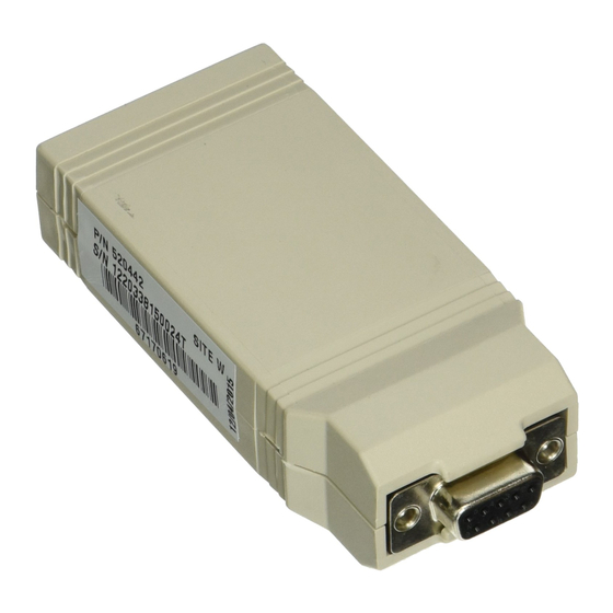
8 data bits, 1 start bit, 1 stop bit, and no parity. IntelliTouch i-Link Adapter Location The IntelliTouch i-Link adapter is for indoor use only and should be located within 25 feet of the home automation system. Serial RS-232 (DB-9S) -
Page 23: Connecting To The Home Automation Interface
Connecting to the Home Automation Interface The IntelliTouch i-Link Protocol Interface adapter is identified as a RS-232 Data Communications Equipment (DCE) device. The IntelliTouch i-Link adapter DB-9S connector can use straight-through wiring to connect to a DTE (Data Terminal Equipment) device such as a Home Automation interface or PC/Laptop DB-9S Serial port connector. -
Page 24: Connecting To The I-Link Adapter
For connection details, see Connection Diagram, page 19. To connect the four conductor cable to the IntelliTouch i-Link adapter (see Figure 1): Run a four conductor cable (22 AWG UL approved) from either the Indoor Control Panel or the Power/Load Center location to the IntelliTouch i-Link adapter. -
Page 25: Connecting To The Indoor Control Panel
Screw Terminal Connector Wire Exit Hole Connect to Indoor Control Panel or Personality Board Notch Figure 1 IntelliTouch i-Link Protocol Interface Adapter User’s Guide... - Page 26 Connecting to the Indoor Control Panel To connect the i-Link communication cable to the Indoor Control Panel: Switch the main power OFF to the Load/Power Center. Route the four conductor cable from the IntelliTouch i-Link adapter to the location of the Indoor Control Panel.
-
Page 27: Connecting To The Personality Board
Load Center enclosure low voltage raceway. The following steps describe how to connect the four conductor cable to the Personality board that connects directly to the IntelliTouch i-Link adapter. To connect the cable to the Personality board: Switch the main power OFF to the Load/Power Center. -
Page 28: Start-Up With Mobiletouch Wireless Control Panel
Slide the case on to the transceiver back plate. Secure the transceiver case with the two retaining screws. Switch the main power on to the Load/Power Center. The i-Link adapter start-up procedure is complete. Strip back the cable conductors ¼ in. Insert the four wires into the screw terminals on either COM PORTS (J7 and J8) plugs located on the left side of the Personality board. - Page 29 Left side of Personality Board Power Center IntelliTouch i-Link Protocol Interface Adapter User’s Guide...
- Page 30 Reconnect the transceiver screw terminal connector onto the transceiver board. Slide the case on to the transceiver back plate. Secure the transceiver case with the two retaining screws. Switch the main power on to the Load/Power Center. The i-Link adapter start-up procedure is complete. Case Transceiver...
-
Page 31: Glossary Of Terms
Power Center: Same as Load Center with the exception of the circuit breaker base. Screw Terminal: Removable connector that may attach to circuit board with multiple sockets (anywhere from 2 to 12) to receive wires from controllers and sensors; wires held by screw terminals; IntelliTouch i-Link Protocol Interface Adapter User’s Guide... - Page 32 *520450* P/N 520450 - Rev B IntelliTouch i-Link Protocol Interface Adapter User’s Guide...