Table of Contents
Advertisement
Quick Links
®
Installation, Operation and Maintenance Manual
Please read and save these instructions. Read carefully before attempting to assemble, install, operate or maintain the
product described. Protect yourself and others by observing all safety information. Failure to comply with instructions
could result in personal injury and/or property damage! Retain instructions for future reference.
Please record the Serial, Model #, and Mark for the hood and other equipment for future reference.
Serial #: _______________________
Serial #: _______________________
Serial #: _______________________
Serial #: _______________________
Serial #: _______________________
Serial #: _______________________
Serial #: _______________________
Serial #: _______________________
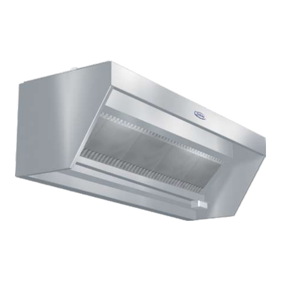
Proximity Hood
Model #: ______________________
Model #: ______________________
Model #: ______________________
Model #: ______________________
Model #: ______________________
Model #: ______________________
Model #: ______________________
Model #: ______________________
Model Proximity (Backshelf)
Kitchen Hoods
Mark: _________________
Mark: _________________
Mark: _________________
Mark: _________________
Mark: _________________
Mark: _________________
Mark: _________________
Mark: _________________
PN 458294
Advertisement
Table of Contents

Related Manuals for Greenheck PN 458294


Summary of Contents for Greenheck PN 458294
- Page 1 Model #: ______________________ Model #: ______________________ Model #: ______________________ Model #: ______________________ Model #: ______________________ Model #: ______________________ Model #: ______________________ Model #: ______________________ PN 458294 Kitchen Hoods Mark: _________________ Mark: _________________ Mark: _________________ Mark: _________________ Mark: _________________ Mark: _________________...
-
Page 2: Table Of Contents
Table of Contents Receiving and Handling ............. 3 Hood Weights . -
Page 3: Receiving And Handling
Receiving and Handling Upon receiving the equipment, check for both obvious and hidden damage. If damage is found, record all necessary information on the bill of lading and file a claim with the final carrier. Check to be sure that all parts of the shipment, including accessories, are accounted for. -
Page 4: Installation
Installation NOTE: If you have a Back Supply Plenum, this must be installed before the hood. Please see page 8 now. Prior to installation, check with local authorities having jurisdiction on clearances to combustible surfaces. With the hood still inside its packing crate, position the unit beneath its installation location. -
Page 5: Filler Panels
End Filler Panel Installation Instructions End filler panels may be shipped loose for field installaton or are facory mounted to the hood. If fillers are factory mounted to hood, skip this section. 1. Uncrate the hood and lay it on the floor with protective material between the hood and the floor. 2. -
Page 6: Ductwork
Ductwork Exhaust As specified in NFPA 96, Ch. 7.5 (latest edition), exhaust duct systems must be constructed in the following manner: Materials. Ducts shall be constructed of and supported by carbon steel not less than 1.37 mm (0.054 in.) (No. 16 MSG) in thickness or stainless steel not less than 1.09 mm (0.043 in.) (No. 18 MSG) in thickness. -
Page 7: External Supply Plenums Installation
External Supply Plenum Installation The purpose of the external supply plenum is to provide make-up air to an exhaust hood to maintain the air balance in the space. The external supply plenum must be hung independent of the hood. Follow the instructions for hanging the following supply plenums: Horizontal, Air Curtain and Variable. See page 8 for Back Supply Plenum. -
Page 8: Back Supply Plenum Installation
Installing the Back Supply Plenum Installing the Supply Duct Collar 1. Find the center of the Back Supply Plenum. 2. If the Back Supply Plenum is less than 9 ft. 10 in. (299.72 cm) long, cut opening at the suggested location, centering the opening over the center of the Back Supply Plenum. -
Page 9: Hanging The Hood
Hanging the Hood with Back Supply Plenum Before hanging the hood according to the hood installation instructions, please check the following: 1. Make sure the back supply unit is properly secured, as described in steps 5 and 6, page 8. 2. -
Page 10: Enclosure Panel Installation Instructions
Full Enclosure Panels Before installing the enclosure panels, make sure the hood is hung in position with all the ductwork attached and fire system connections completed. 1. Tack-weld or clamp end enclosure panels onto standing seam (clamps provided). 2. Attach the end enclosure panels to the wall (fasteners by others). 3. - Page 11 Plate Shelf with Duct Enclosure Panels Before installing the enclosure panels, make sure the hood is hung in position with all the ductwork attached and the fire system connections completed. Plate shelf will be factory mounted to hood (shown loose). 1.
- Page 12 Passover Shelf with Duct Enclosure Panels Before installing the enclosure panels, make sure the hood is hung in position with all the ductwork attached and fire system connections completed. 1. Attach mounting channels to the wall in the correct location. 2.
-
Page 13: Backsplash Panel Installation Instructions
Backsplash Panel Installation Instructions 1. Layout backsplash panels according to Fig. 18 Note offset in panel for overlap. If the backsplash panel length is greater than 46 in. (1168.4 mm), it will be shipped in multiple pieces. Be sure offsets match up to other panels. -
Page 14: Duct Collar Installation Instructions
Duct Collar Installation Exhaust Ducts 1. If the exhaust duct has been factory mounted, skip this section. 2. The exhaust duct must be located within the shaded region of Fig. 20. Note dimensions. Dimension Y assumes a 3 in. (76.2 mm) integral airspace on the hood back. When no 3 in. (76.2 mm) integral airspace is present, Y=0 in. -
Page 15: Exhaust Air Balancing Baffle (Eabb)
Exhaust Air Balancing Baffles (EABB) This is a guide to assist in determining if multiple hoods on one fan can be balanced to have equal static pressure. For multiple hoods on one fan to achieve their designed exhaust flow, all of the hoods must have equal static pressure at their designed exhaust flow. -
Page 16: Balancing The Kitchen Exhaust
Balancing the Kitchen Exhaust System A. To determine the proper dining room air balance: 1. Refer to engineering drawings to determine total exhaust CFM from dining areas. (Exhaust fans, heating and air conditioning units, restrooms, etc.) 2. Determine the total CFM of make-up air supplied to dining area. 3. - Page 17 Measure the velocity of each location. A digital 2.75 in. (70 mm) rotating vane anemometer or equivalent is suggested. The center of the anemometer should be held 2 in. (50 mm) from the face of the filters as shown in Fig. 22. It is helpful to make a bracket to keep the anemometer at the 2 in.
- Page 18 B. Supply (If Applicable): Example for Perforated Face Supply 1. Hood set up If the make-up air unit has a temperature control, it should be used to keep the supply air at the desired room discharge air temperature. 2. Measure Velocities Divide the perforated face panel into a grid of equal areas, each approximately 4 in.
- Page 19 Testing Hood Air Volume Baffle Filters Style Hoods with the Shortridge Meter A. Exhaust With all the filters in place, determine the total hood exhaust volume with a shortridge meter as follows: 1. All cooking equipment should be on. If the hood has internal short circuit make-up air, it should be turned off.
-
Page 20: High Velocity Cartridge Filters (Gk Series)
High Velocity Cartridge Filters A. Exhaust With all the filters in place, determine the total hood exhaust volume with a rotating vane anemometer as follows: 1. All cooking equipment should be on. If the hood has internal short circuit make-up air, it should be turned off. 2. - Page 21 High Velocity Cartridge Filters A. Exhaust With all the filters in place, determine the total hood exhaust volume with a shortridge meter as follows: 1. All cooking equipment should be on. If the hood has internal short circuit make-up air, it should be turned off. 2.
- Page 22 Grease-X-Tractor™ High Efficiency Filters or Grease Grabber™ Multi-Filtration System A. Exhaust With all the filters in place, determine the total hood exhaust volume with a rotating vane anemometer as follows: 1. All cooking equipment should be off. If the hood has internal short circuit make-up air, it should be turned off.
-
Page 23: High Efficiency Filters (Gx Series)
Grease-X-Tractor™ High Efficiency Filters or Grease Grabber™ Multi-Filtration System A. Exhaust With all the filters in place, determine the total hood exhaust volume with a shortridge meter as follows: 1. All cooking equipment should be on. If the hood has internal short circuit make-up air, it should be turned off. -
Page 24: Fire Suppression Wiring Diagrams
Amerex Wiring Plan View MICROSWITCH INSTALLER PROVIDED JUNCTION BOXES BASIC WIRING DIAGRAM RED (COMMON) YELLOW (N.O) MICROSWITCH BASIC WIRING DIAGRAM RED (COMMON) YELLOW (N.O) MICROSWITCH NOTES: DENOTES FIELD INSTALLATION DENOTES FACTORY INSTALLATION 3. GAS VALVE: UL LISTED ELECTRICALLY-OPERATED SAFETY VALVE FOR NATURAL OR LP GAS AS NEEDED OF APPROPRIATE PRESSURE AND TEMPERATURE RATING, 110V/60HZ OR AMEREX GAS VALVES, PN 12870, 12871, 12872, 12873, 12874, 12875 and 12876. -
Page 25: Ansul Wiring Plan View
Field Wiring for the Ansul Snap-Action Switch Ansul Wiring Plan View 2 Snap-Action Switches provided by Greenheck may be wired as shown. Four typical examples shown Equipment Power to cooking equipment Shunt Trip Breaker 120 VAC Electric gas valve - If reset relay is used, see option A or B at right. -
Page 26: Overall Wiring Plan View
Overall Wiring Plan View CENTER CONTROL MAKE-UP POWER SUPPLY Fig. 39 Proximity Hood ®... -
Page 27: Wiring For Switch Panels
Wiring for Switch Panels THE DIAGRAMS BELOW SHOW A TYPICAL HOOD SWITCH PANEL REMOTE MOUNTED. FOR HOOD MOUNTED SWITCHES REFER TO THE WIRING CONNECTION DECAL ON THE The diagrams below show a typical hood switch panel remote mounted. For hood mounted switches COVER OF THE JUNCTION BOX ON THE HOOD TOP. -
Page 28: Maintenance
Maintenance Daily Maintenance 1. Wipe grease from exposed metal surfaces on the hood interior using a clean, dry cloth. 2. Visually inspect the filters for grease accumulation. Wash as needed. 3. Remove grease cup, empty contents, and replace cup. Weekly Maintenance 1. -
Page 29: Grease Grabber
Grease Grabber™ Multi-Stage Filtration System For use in Model GG__ Canopy Hoods Only Installation Note: Never install the Second Stage filter in the front filter channel. The Second Stage filter must be installed behind a UL Classified Grease-X-Tractor™ primary filter Model HE or GX. 1. -
Page 30: Grease Grabber
Grease Grabber™ Filter Cleaning Step 1 Remove the front GX filters: (1A) Remove middle filters first, (1B) slide ends toward middle and remove. GX Filters, first row of filters Step 2 Release the hooks that hold the filters together. Slide the top hook upward and the bottom hook downward until the hook releases. -
Page 31: Filter Washing Frequency Guide
Filter Washing Frequency Guide NOTE: Standard cooking will turn the beads yellow in color. Open flame cooking will cause the beads to blacken. Neither affects the performance of the beads. Caution: To prevent damage to filter media, do not wash second stage filters in detergents that contain hydroxides such as sodium hydroxide or potassium hydroxide. -
Page 32: Troubleshooting
Troubleshooting Problem: Exhaust fan is not operating or is not operating at design levels. Is the fan receiving power? Is the belt loose or broken? Is the fan rotating in correct direction? Is the make-up air operating? Does the airflow need to be increased? Does the fan vibrate? Problem: Hood is full of smoke. - Page 33 Troubleshooting Problem: Smoke blows away before reaching the bottom of the hood. Are there pass-thru windows near the hood? Is this an air curtain hood? Is the make-up air part of the hood or an attached plenum? Problem: Pilot lights are being blown out or cooking equipment is being cooled by make-up air. Are there drafts from make-up air? Problem: Cold air can be felt by the cook at the hood.
-
Page 34: Replacement Parts
Before calling your manufacturers representative to report a problem, have the following information available: 1. Review / summary of troubleshooting section in installation operation manual. 2. Hood model and serial number. 3. Current cooking equipment line-up. 4. Size of hood (length, width and height). 5. -
Page 35: Maintenance Log
Maintenance Log Date __________________ Time _____________ AM/PM Notes:___________________________________________ _________________________________________________ _________________________________________________ _________________________________________________ _________________________________________________ Date __________________ Time _____________ AM/PM Notes:___________________________________________ _________________________________________________ _________________________________________________ _________________________________________________ _________________________________________________ Date __________________ Time _____________ AM/PM Notes:___________________________________________ _________________________________________________ _________________________________________________ _________________________________________________ _________________________________________________ Date __________________ Time _____________ AM/PM Notes:___________________________________________ _________________________________________________ _________________________________________________ _________________________________________________ _________________________________________________ Date __________________ Time _____________ AM/PM... - Page 36 As a result of our commitment to continuous improvement, Greenheck reserves the right to change specifications without notice. Contact Greenheck Fan Corporation: Phone: (715) 359-6171 • Fax: (715) 355-2399 • E-mail: gfcinfo@greenheck.com • Website: www.greenheck.com ® 458294 • Proximity Hood, Rev. 3, March 2008 Copyright 2008 © Greenheck Fan Corp.