Table of Contents
Advertisement
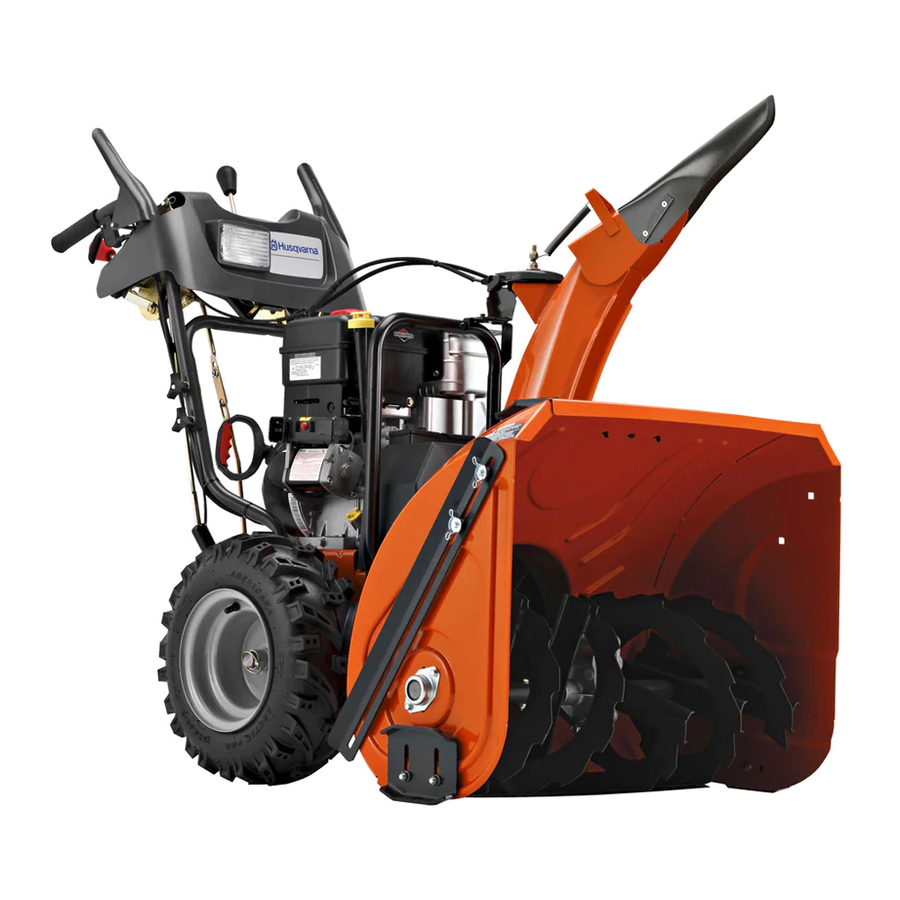
Operator's Manual
ST230E
Gasoline containing up to 10% ethanol (E10) is acceptable for use in this machine.
The use of any gasoline exceeding 10% ethanol (E10) will void the product warranty.
Please read the owner's manual carefully and make sure you
understand the instructions before using the machine.
115 48 72-27 Rev. 1
English
Advertisement
Table of Contents

Related Manuals for Husqvarna ST230E


Summary of Contents for Husqvarna ST230E
- Page 1 Operator’s Manual ST230E Gasoline containing up to 10% ethanol (E10) is acceptable for use in this machine. The use of any gasoline exceeding 10% ethanol (E10) will void the product warranty. Please read the owner's manual carefully and make sure you understand the instructions before using the machine.
-
Page 2: Safety Rules
IMPORTANT Safe Operation Practices for Walk-Behind Snow Throwers This snow thrower is capable of amputating hands and feet and throwing objects. Failure to observe the following safety instructions could result in serious injury. WARNING: Snow throwers have ex- Look for this symbol to point out im- posed rotating parts, which can cause por tant safety precautions. -
Page 3: Table Of Contents
Clearing a Clogged Discharge Chute 6. When cleaning, repairing or inspecting the snow thrower, stop the engine and make certain the collector/impel- Hand contact with the rotating impeller inside the discharge ler and all moving parts have stopped. Disconnect chute is the most common cause of injury associated with the spark plug wire and keep the wire away from the snow throwers. - Page 4 PARTS PACKED SEPARATELY IN CARTON (1) FUEL STABILIZER PACKET (1) MULTI- WRENCH (180684) (1) POWER CORD SAFTEY IGNITION KEY (S) (198563) (193071) (1) AUGER CONTROL ROD (1) DISCHARGE CHUTE EXTRA SHEAR BOLTS AND NUTS (6) SHOULDER (6) LOCKNUTS BOLT 1/4-20 x 1-3/4 1/4-20 (192090) (73800400)
-
Page 5: Assembly / Pre-Operation
ASSEMBLY / PRE-OPERATION Read these instructions and this manual in its entirety before you attempt to assemble or operate your new SPEED snow thrower. Reading the entire manual will familiar- CONTROL ize you with the unit, which will assist you in assembly, operation and maintenance of the product. - Page 6 ASSEMBLY / PRE-OPERATION INSTALL TRACTION DRIVE CONTROL ROD INSTALL AUGER CONTROL ROD (See Figs. 5 and 6) (See Figs. 3 and 4) 1. Retrieve vinyl sleeve and spring from bag of parts and retrieve the auger control rod from carton chute tray. The traction drive control rod has the long loop on the end Slide straight rod end through the small hole in the of the spring as shown.
- Page 7 ASSEMBLY / PRE-OPERATION INSTALL DISCHARGE CHUTE / CHUTE ROTATER INSTALL CHUTE DEFLECTOR REMOTE CONTROL HEAD (See Fig. 7) (See Figs. 8 and 9) 1. Install remote cable bracket to discharge chute with NOTE: The multi-wrench provided in your parts bag may 5/16-18 carriage bolt and 5/16-18 locknut as shown.
-
Page 8: Operation
OPERATION KNOW YOUR SNOW THROWER READ THIS OWNER'S MANUAL AND ALL SAFETY RULES BEFORE OPERATING YOUR SNOW THROWER. Compare the illustrations with your snow thrower to familiarize yourself with the location of various controls and adjustments. Save this manual for future reference. These symbols may appear on your snow thrower or in literature supplied with the product. - Page 9 OPERATION DISCHARGE CHUTE CONTROL LEVER GAS O LINE ELECTRIC AUGER DEFLECTOR REMOTE FILLER CAP START CONTROL CONTROL LEVER BUTTON DRIVE SPEED LEVER CON TROL LEVER TRACTION MUF FLER RECOIL DRIVE (AUXILIARY) CONTROL STARTER LEVER HANDLE CHUTE CHOKE DE FLEC TOR CON- TROL PRIM ER...
- Page 10 OPERATION The operation of any snow thrower can result TO USE CHOKE CON TROL (See Fig. 13) in foreign objects thrown into the eyes, which The choke con trol is located on the en gine. Use the choke can result in severe eye damage. Always wear control when ev er you are starting a cold en gine.
- Page 11 OPERATION TO THROW SNOW (See Fig. 15) TO MOVE FORWARD AND BACKWARD (See Fig. 17) The auger rotation is controlled by the auger control lever SELF-PROPELLING, forward and reverse movement of located on the right side handle. the snow thrower, is controlled by the traction drive control lever located on the left side handle.
-
Page 12: Before Starting The Engine
OPERATION POWER STEERING OPERATION (See Fig. 18) SCRAPER BAR (See Fig. 19) Steering triggers are used to assist in steering your snow The scraper bar is not adjustable, but is reversible. After thrower. The triggers are located on the underside of each con sid er able use it may become worn. - Page 13 OPERATION TO START ENGINE CAUTION: Alcohol blended fuels (called gas o- • Be sure fuel shut-off valve is in the “OPEN” position. hol or using ethanol or methanol) can attract moisture which leads to separation and for ma- Your snow thrower engine is equipped with both a 120 Volt tion of acids dur ing storage.
-
Page 14: Snow Throwing Tips
OPERATION NOTE: Over priming may cause flooding, preventing the SNOW THROWING TIPS engine from starting. If you do flood the engine, wait a few • Always operate the snow thrower with the engine at minutes be fore at tempt ing to start and DO NOT push the full throttle. -
Page 15: Maintenance Schedule
MAINTENANCE GENERAL REC OM MEN DA TIONS LUBRICATION CHART The warranty on this snow thrower does not cover items that have been sub ject ed to operator abuse or negligence. ➀ SAE 30 Motor Oil To receive full value from the warranty, operator must ➁... - Page 16 MAINTENANCE BELTS TO CHANGE ENGINE OIL Check belts for deterioration and wear after every 50 hours Determine temperature range anticipated before next oil of operation and replace if necessary. The belts are not change. All oil must meet API service classification SG–SL. ad just able.
-
Page 17: Service And Adjustments
SERVICE AND ADJUSTMENTS 1. Disengage all controls and move throttle control to WARNING: To avoid serious injury, before STOP position. Wait for all moving parts to stop. performing any service or ad just ments: 2. Remove safety ignition key and disconnect spark plug 1. -
Page 18: To Replace Belts
SERVICE AND ADJUSTMENTS TO REPLACE BELTS (See Fig. 24) 8. RELIEVE TENSION ON TRACTION DRIVE BELT IDLER and remove traction drive belt from around The auger and traction drive belts are not adjustable. If the pulleys. belts are damaged or begin to slip from wear, they should be replaced. - Page 19 SERVICE AND ADJUSTMENTS ENGINE TO REMOVE WHEELS (See Fig. 25) • Remove the wheel pin and retainer pin and remove SEE ENGINE MANUAL. wheel from axle. CARBURETOR NOTE: To seal punctures or prevent flat tires due to slow leaks, tire sealant may be purchased from your local parts Your carburetor is not adjustable.
-
Page 20: Storage
STORAGE ENGINE OIL Immediately prepare your snow thrower for storage at the end of the season or if the unit will not be used for 30 Drain oil (with engine warm) and replace with clean engine days or more. oil. (See “ENGINE” in the Maintenance section of this man ual). -
Page 21: Troubleshooting
TROUBLESHOOTING See appropriate section in manual unless directed to an authorized service center/department. PROBLEM CAUSE CORRECTION Does not start 1. Fuel shut-off valve (if so 1. Turn fuel shut-off valve to OPEN position. equipped) in OFF position. 2. Safety ignition key 2. - Page 22 (a) Engines and Attachments.Except where otherwise indicated on Exhibit A, all Engines and Attachments are not covered by this Limited Warranty. In most cases, these items are NOT manufactured by Husqvarna in which case they may be covered separately by their respective manufacturer's warranties if one is provided and included with the product at the time of purchase.
- Page 23 10. Authorized Husqvarna Servicing Dealer/Center. In order to obtain warranty coverage it is your responsibility (at your expense) to deliver or ship your Husqvarna unit to an authorized Husqvarna Servicing Dealer/Center and arrange for pick-up or return of your unit after the repairs have been made.
-
Page 24: Warranty
Riding Lawn Tractors: Frame, Chassis, Front Axle 5 Years No Warranty No Warranty Engine* Transmission (if made by Husqvarna/Peerless) 3 Years No Warranty No Warranty Transmission (if third party)** XLS Models only - stamped deck shell. Armor Protected Limited Warranty... - Page 25 ** See reference 1 (b) of the warranty statement. RZ - Two (2) Year Consumer warranty, parts & labor, with Hydro-Gear Distributor network. EZ - One (1) Year Commercial warranty, parts & labor, with Husqvarna. Two (2) Year Consumer warranty, parts & labor, with Hydro-Gear Distributor network.
- Page 26 SERVICE NOTES...
- Page 27 SERVICE NOTES...
- Page 28 08/03/2012 SR...