Table of Contents
Advertisement
Quick Links
Advertisement
Table of Contents

Related Manuals for Alcatel OMNIACCESS 4308


Summary of Contents for Alcatel OMNIACCESS 4308
- Page 1 OmniAccess 4308 Wireless LAN Switch Installation Guide...
- Page 2 OmniAccess 4308: Installation Guide Copyright Copyright © 2005 Alcatel Internetworking, Inc. All rights reserved. Specifications in this manual are subject to change without notice. Originated in the USA. Trademarks Alcatel®, the Alcatel logo, AOS-W, and OmniAccess, and the OmniAccess 4308 are trademarks of Alcatel in the United States and certain other countries.
- Page 3 Electromagnetic Interference FCC - Class A This equipment has been tested and found to comply with the limits for a Class A digital device, pursuant to Part 15 of the FCC Rules. These limits are designed to provide reasonable protection against harmful interference when the equipment is operated in a commercial environment.
-
Page 4: Laser Notice
OmniAccess 4308: Installation Guide Warning—This is a Class A product. In a domestic environment, this product may cause radio interference in which case the user may be required to take adequate measures. EU - Class A This product complies with EN55022 Class A and EN55024 standards. -
Page 5: Table Of Contents
Contents Preface ..Overview of this Manual ..Related Documents viii ... Text Conventions viii ... Contacting Alcatel To the Network Manager The Alcatel Wireless LAN... - Page 6 OmniAccess 4308: Installation Guide Ports ..... . Appendix B ....
-
Page 7: Preface
A key to the various text conventions used throughout this manual Alcatel support and service information Overview of this Manual This manual is for trained technicians responsible for installing the OmniAccess 4308 Wireless LAN Switch. This manual is organized as follows: Chapter “System Overview”—Describes the main features of this product, including physical diagrams. -
Page 8: Related Documents
OmniAccess 4308: Installation Guide Related Documents The following items are part of the complete documentation for the Alcatel system: Alcatel OmniAccess 4308 Wireless LAN Switch Installation Guide (this manual) Alcatel AOS-W User Guide Alcatel AP installation guide Text Conventions The following conventions are used throughout this manual to emphasize... -
Page 9: Contacting Alcatel
Contacting Alcatel Web Site Main Site http://www.alcatel.com Support http://www.alcatel.com/enterprise Telephone Numbers Main US/Canada (800) 995-2612 Main Outside US (818) 880-3500 Preface... - Page 10 OmniAccess 4308: Installation Guide Part 031638-00 May 2005...
-
Page 11: To The Network Manager
To the Network Manager As with any full-featured network equipment, deploying the Alcatel Wireless LAN (Wireless LAN) solution requires a degree of planning. The process may involve multiple components as well as various individuals in your organization. As the network manager, you should become familiar with the components and deployment summary outlined in this section. -
Page 12: Deployment Summary
Boot the system and perform the initial power-on test, examining the LEDs and console messages to ensure proper operation. The Alcatel OmniAccess 4308 Wireless LAN Switch Installation Guide provides the necessary instructions. Initial configuration of the Alcatel Wireless LAN Switch... -
Page 13: Monitoring And Maintenance
Determine how many access points are needed and where they should be located. Simulate network failures and recovery characteristics, and adjust place- ment if necessary. The Alcatel AOS-W User Guide provides instructions. Physical installation of the Alcatel Wireless Access Points This requires a trained technician. - Page 14 OmniAccess 4308: Installation Guide Part 031638-00 May 2005...
-
Page 15: Chapter 1 System Overview
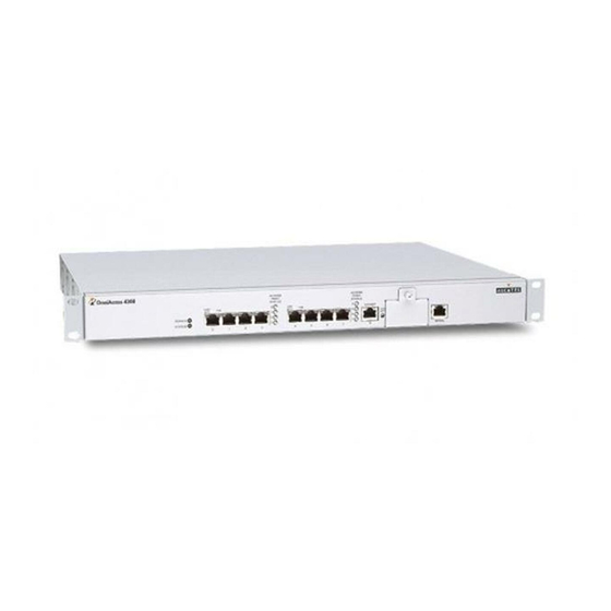
HAPTER System Overview The OmniAccess 4308 WLAN Switch is an enterprise-class switch which connects, controls, and intelligently integrates wireless Access Points (APs) and Air Monitors (AMs) into the wired LAN. This chapter introduces you to the Alcatel Wireless LAN Switch. It describes the general features of the system and illustrates key physical elements. -
Page 16: Physical Description
ACCESS POINT POINT STATUS STATUS LNK/ LNK/ GIGABIT LNK/ POWER STATUS SERIAL OAW-4308SX ACCESS ACCESS POINT POINT STATUS STATUS LNK/ LNK/ GIGABIT LNK/ POWER STATUS SERIAL OAW-4308T Rear View 1-1 OmniAccess 4308 WLAN Switch Systems IGURE Part 031638-00 May 2005... - Page 17 Chapter 1 System Indicator LEDs 1-1 System LEDs ABLE State Description Power Green Switch is receiving proper power. Switch is powered off. Status Green Switch has booted and is functioning properly. Switch is booting, loading software, or has failed. Eight FE ports These network ports are used for connecting wireless APs, such as the Alcatel Wireless Access Point, as well as wired LAN segments.
-
Page 18: The Alcatel Omniaccess 4304
Alcatel OmniAccess 4308. The Alcatel OmniAccess 4304 software license can be upgraded to an Alcatel OmniAccess 4308 and able to support up to 16 Access Points. For information on upgrading the Alcatel OmniAccess 4304 to an Alcatel OmniAccess 4304, contact your Alcatel sales representative to visit the support website. -
Page 19: Chapter 2 Installing The Chassis
Connecting power to the Alcatel Wireless LAN Switch Pre-Installation Checklist During installation, you will need the following: OmniAccess 4308 Wireless LAN Switch chassis Two mounting brackets (included) Six 6-32 flat head screws (included) Four 12-24 screws (included) or screws as appropriate for... -
Page 20: Precautions
OmniAccess 4308: Installation Guide Precautions —Hazardous energy is always present while the OmniAccess AUTION 4308 Wireless LAN Switch is plugged into an electrical outlet. Remove all rings, jewelry, and other potentially conductive material before working with this product. Never insert foreign objects into the chassis or any other component, even when the Alcatel Wireless LAN Switch is unpowered or unplugged. -
Page 21: Requirements
Chapter 2 Requirements Rack Mounting Kit Using the included rack mounting kit, you can mount the Alcatel Wireless LAN Switch in a standard 19-inch network equipment rack. The rack mounting kit contains the following parts: 6-32 Flat Head Screws 12-24 Screws Right Left Bracket... -
Page 22: Selecting A Location
OmniAccess 4308: Installation Guide Selecting a Location The Alcatel Wireless LAN Switch, like other network and computing devices, requires an “electronics friendly” environment. Reliable power Make sure that your electrical outlet is compatible with the Alcatel Wireless LAN Switch. The switch power input is auto-ranging and accepts 90~132/180~264 VAC, 50 to 60 Hz, 3.5/2.0 A. -
Page 23: Mounting The Chassis
Chapter 2 Mounting the Chassis Make sure that your rack environment meets requirements (see “Selecting a Location” page Attach the rack mounting brackets to the switch chassis as shown in Figure 2-2. 6-32 flat head screws R IA G IG 2-2 Attaching the Rack Mounting Brackets IGURE Orient both brackets so that the narrow flange faces the front. - Page 24 OmniAccess 4308: Installation Guide Attach the Alcatel Wireless LAN Switch to the rack. —To avoid personal injury or damage to equipment, get help AUTION for lifting and positioning the Alcatel Wireless LAN Switch. Also, do not install the Alcatel Wireless LAN Switch in any fashion where instability or uneven mechanical loading may occur.
- Page 25 Chapter 2 —Some cabinets require different screws which are not included. Make sure that you use the correct screws or fasteners for your rack system. Adhere to clearance requirements. Keep Clear for Air Intake Keep Open to Access R IA G IG Keep Clear for Air Exhaust...
-
Page 26: Connecting Power
OmniAccess 4308: Installation Guide Connecting Power —This procedure should be performed by a trained technician. AUTION Make sure you understand the procedure and all precautions. Before beginning, read the entire procedure. Make sure you understand all the precautions in these steps as well as those on page Make sure that your site’s electrical system is compatible with... -
Page 27: Chapter 3 Verifying The Installation
HAPTER Verifying the Installation Once the Alcatel Wireless LAN Switch is physically installed, run the following power-on test: Check for the proper power indicators. Immediately upon power up, you should observe the following: The system Power LED lights solid green The system Status LED is initially off while booting Check the fans to verify they are working. - Page 28 OmniAccess 4308: Installation Guide You are now ready to perform the initial setup as described in the Alcatel Quick Start Guide (which is included in the Accessory Kit). Part 031638-00 May 2005...
-
Page 29: Appendix A Power Management
System and Location Name of Alcatel Wireless LAN Switch Location POE Power Requirements Determine the power output required by switch ports that supply Power Over Ethernet (POE): A-1 OmniAccess 4308 Power Requirements ABLE Power Number Power Component Name Rating... - Page 30 OmniAccess 4308: Installation Guide —Recalculate the worksheet numbers whenever devices using POE are connected to or disconnected from the network ports. Part 031638-00 May 2005...
-
Page 31: Appendix B Ports
PPENDIX Ports The OmniAccess 4308 Wireless LAN Switch has a number of different ports, each with their own purpose: Eight Fast Ethernet (FE) ports Used for connecting to Access Points (APs) and wired LAN segments. These 10/100 Mbps FE ports aggregate and route traffic under the direction of the switch’s internal software. -
Page 32: Fe Network Ports
Special cables and adapters may be necessary to use SPOE features with some equipment. See material starting on page 20 for port and cable specifications. Physical Description & LEDs ACCESS ACCESS POINT POINT STATUS STATUS LNK/ LNK/ B-1 OmniAccess 4308 FE Network Ports IGURE Part 031638-00 May 2005... - Page 33 Appendix B Eight FE Network Ports These ports are used to connect APs and wired LAN segments to the Alcatel Wireless LAN Switch. These ports provide 10/100 Mbps Fast Ethernet connectivity, and in some cases, power and serial connectivity as well. All FE ports automatically sense and negotiate speed, duplex, and MDI/MDX settings.
-
Page 34: Pin Outs
OmniAccess 4308: Installation Guide Access Point Status LEDs Each LED represents the status of APs connected to a specific port on the switch. During operation, the LEDs provide the following information: B-3 AP Status LED ABLE Status Description Red (solid) An AP on this port has failed (highest precedence). -
Page 35: Cables
Appendix B Cables The type of cable required for each port depends on the device being connected: Direct connection to a SPOE compatible device This requires an 8-conductor Category 5 UTP Ethernet cable with an RJ-45 male connector. A straight-through cable is required to preserve POE voltage polarity. -
Page 36: Ge Uplink Port
1000BASE-T copper connector (standard model OAW-4308T) GIGABIT LNK/ 1000BASE-SX fiber-optic connector (optional model OAW-4308SX) GIGABIT LNK/ B-3 Alcatel OmniAccess 4308 Gigabit Ethernet IGURE Ports —The Gigabit interface is not user-replaceable. Do not remove the port cover plate. Part 031638-00 May 2005... -
Page 37: Cables
Appendix B Gigabit Ethernet port (copper or fiber-optic, depending on the option) LNK/ACT LED B-5 GE LNK/ACT LED ABLE Status Description No Ethernet link on the port. Green An Ethernet link has been established on the port, but no data is currently being transmitted or received. Flashing The port is transmitting or receiving data. - Page 38 OmniAccess 4308: Installation Guide B-7 Fiber-Optic GE Cable Characteristics ABLE Item Specification Cable 50 µm multimode fiber Connector SC-type fiber optic Range Up to 550 m (1800 feet) —The fiber-optic interface uses a laser transceiver. Use of AUTION controls or adjustments of performance or procedures other than those specified herein may result in hazardous radiation exposure.
-
Page 39: Serial Console Port
Appendix B Serial Console Port The serial console port is located on the front panel of the Alcatel Wireless LAN Switch. This port is for connecting a local management console and can be used to access the text-based Command-Line Interface (CLI) to configure, manage, and troubleshoot the Alcatel Wireless LAN Switch. -
Page 40: Communications Settings
OmniAccess 4308: Installation Guide To connect the required RS-232 serial cable to a terminal with a DB-9 male port, use the included adapter. Pin-outs are shown in Figure B-5 RJ-45 Female Internal DB-9 Female Pin-Out Connections Pin-Out RJ-45 DB-9 Ground... -
Page 41: Appendix C Specifications
PPENDIX Specifications Physical C-1 Physical Specifications ABLE Item Specification Size Height 4.45 cm (1.75 inches) Width 44.2 cm (17.4 inches) Depth 33.3 cm (13.1 inches) Weight 4.5 KG (10 lbs.) Environment C-2 Environmental Specifications ABLE Item Specification Temperature Operating: 0 to 40 ºC (32 to 104 ºF) Storage: 0 to 50 ºC (32 to 122 ºF) Humidity 5% to 95% (non-condensing) - Page 42 OmniAccess 4308: Installation Guide Operation C-3 Operational Specifications ABLE Item Specification Power 90~132/180~264 VAC, 50-60 Hz, 3.5/2.0 A Network Command-Line Interface and HTML Web-browser Management Interface Standards IEEE 802.1x, IEEE 802.3 10BASE-T, IEEE 802.3u 100BASE-TX, IEEE 802.3ab 1000BASE-T (model OAW-4308T), IEEE 802.3z 1000BASE-SX (model OAW-4308SX)
- Page 43 Notes Notes...