Denon AVC-A1XV Operating Instructions Manual
Av surround amplifier
Hide thumbs
Also See for AVC-A1XV:
- Service manual (254 pages) ,
- Operating instructions manual (70 pages) ,
- Operating manual (18 pages)
Table of Contents
Advertisement
AV SURROUND AMPLIFIER
AVC-A1XV
OPERATING INSTRUCTIONS
We greatly appreciate your purchase of the AVC-A1XV.
2
To be sure you take maximum advantage of all the features the AVC-A1XV has to offer, read these instructions
2
carefully and use the set properly. Be sure to keep this manual for future reference should any questions or
problems arise.
"SERIAL NO.
PLEASE RECORD UNIT SERIAL NUMBER ATTACHED TO THE REAR OF THE
CABINET FOR FUTURE REFERENCE"
RC-995
Advertisement
Table of Contents

Related Manuals for Denon AVC-A1XV


Summary of Contents for Denon AVC-A1XV
-
Page 1: Operating Instructions
We greatly appreciate your purchase of the AVC-A1XV. To be sure you take maximum advantage of all the features the AVC-A1XV has to offer, read these instructions carefully and use the set properly. Be sure to keep this manual for future reference should any questions or problems arise. - Page 2 CAUTION: CAUTION • The ventilation should not be impeded by covering the ventilation openings with items, such as newspapers, table-cloths, curtains, etc. RISK OF ELECTRIC SHOCK • No naked flame sources, such as lighted candles, should be placed on the DO NOT OPEN apparatus.
- Page 3 NOTE ON USE / HINWEISE ZUM GEBRAUCH / OBSERVATIONS RELATIVES A L’UTILISATION / NOTE SULL’USO NOTAS SOBRE EL USO / ALVORENS TE GEBRUIKEN / OBSERVERA • Do not let foreign objects in the set. • Keine fremden Gegenstände in das Gerät kommen •...
-
Page 4: Table Of Contents
INTRODUCTION Thank you for choosing the DENON AVC-A1XV Digital Surround A / V amplifier. This remarkable component has been engineered to provide superb surround sound listening with home theater sources such as DVD, as well as providing outstanding high fidelity reproduction of your favorite music sources. - Page 5 Inserting the Batteries .............108 (ZONE3, ZONE4 SELECT mode)........152 Using the Remote Control Unit ..........108 Remote control unit operations during multi-source Operating DENON audio components ......109, 110 playback ...................153 Preset memory ................111 System Setup for multi-zone ...........154 Operating a component stored in the preset memory ...112, 113 Adjustment steps that need to be performed prior to Learning function ..............114...
-
Page 6: Before Using
ACCESSORIES Check that the following parts are included in addition to the main unit: q Operating instructions ..............1 t Remote control unit (RC-995)...........1 w CD-ROM (Operating instructions) ..........1 y R03/AAA alkaline batteries ............4 e Service station list ..............1 u Omnidirectional microphone ............1 r AC cord..................1 i List of preset codes..............1 1 BEFORE USING... -
Page 7: Cautions On Handling
Compact Discs (which number in the thousands nuances with optimum clarity and natural fidelity. of titles). The AVC-A1XV, via a standard digital audio connection 4) AL24 DSP Processing For All Channels from a CD player or DVD player, internally recognizes and For the AVC-A1XV, DENON’s AL24 processing supports multi-... - Page 8 1) ZONE2 Theater Capability surround sound. The AVC-A1XV also adds the ability to have With up to 9.1 system in the main home theater room, the both powered (AVC-A1XV amplified) music and surround AVC-A1XV provides for a second, fully 5.1 capable system in...
-
Page 9: Connections
Power On Volume Level Memory provides a user-definable 3) Digital Audio Delay Function volume level that is activated every time the AVC-A1XV is For optimum picture and sound synchronization, the AVC-A1XV powered up... -
Page 10: Connecting Audio Components
OUTPUT OPTICAL DENON Link terminal Connecting the DIGITAL jacks Use this terminal to connect a DENON DVD player for NOTES: high quality digital multichannel sound. Use these for connections to audio equipment with • Use 75 Ω/ohms cable pin cords for coaxial connections. -
Page 11: Connecting Video Components
• When making connections, also refer to the operating instructions of the other components. • The AVC-A1XV is equipped with a function for up and down converting video signals. (See page 13) The signal connected to the video signal terminal is output to the S-Video and component video monitor out terminals. -
Page 12: Connecting Video Components Equipped With S-Video Jacks
The input selectors for the S-Video inputs and Video inputs work in conjunction with each other. • The AVC-A1XV is equipped with a function for converting video signals. (See page 13) The signal connected to the S-Video signal terminal is output to the composite video and component video monitor out terminals. -
Page 13: Connecting Video Components Equipped With Component
The AVC-A1XV is equipped with a function for up and down converting video signals. Because of this, the AVC-A1XV’s MONITOR OUT jack can be connected to the monitor (TV) with a set of cables offering a higher quality connection, regardless of how the player and the AVC-A1XV’s video input jacks are connected. -
Page 14: Connecting Equipment With Hdmi Terminals
DVD video and other sources, and the multi-channel sound of DVD audio and DVD video. • The HDMI and DVI-D monitor output connectors on the AVC-A1XV can only be used one at a time, not simultaneously. -
Page 15: Connecting Equipment With Dvi Terminals
• Commercially-available DVI cables are available in 24-pin and 29-pin types. The AVC-A1XV supports the 24-pin DVI-D cable. • The HDMI and DVI-D monitor output connectors on the AVC-A1XV can only be used one at a time, not simultaneously. • The on-screen display signals are not outputted from the DVI-D MONITOR OUT. -
Page 16: Connecting The External Input (Ext.in) Jacks
Connecting the external input (EXT. IN) jacks • AVC-A1XV is equipped with two analog external input terminals for 9.1 channels and 5.1 channels. • These jacks are for inputting multi-channel audio signals from an outboard decoder, or a component with a different type of multi-channel decoder, such as a DVD Audio player, or a multi-channel SACD player, or other future multi-channel sound format decoder. -
Page 17: Connecting The Zone2 Jacks
Connecting the ZONE2 jacks 2 ZONE2 preout CONNECTIONS • If another power amplifier is connected, the ZONE2 preout (variable level) jacks can be used to play a different program source in ZONE2 the same time. (See page 147) • The ZONE2 video out is only use for the ZONE2. •... -
Page 18: Denon Link Connections
Digital In Assignment. (See pages 57, 58) • When the input mode is AUTO and the signals are not be able to transferred by DENON LINK, the unit automatically changes over the input to the selected signals (ANALOG, EXT. IN or IEEE1394). -
Page 19: Connecting Ieee1394 Devices
Connecting IEEE1394 devices • Use an S400-compatible 4-pin IEEE1394 cable to connect. • Video signals are not transferred with the AVC-A1XV’s IEEE1394 interface, so when connecting a video device connect the video signals as well. • Assign the IEEE1394 input the input source. (See page 64) -
Page 20: Speaker System Connections
Cooling fan • The AVC-A1XV is equipped with a cooling fan to prevent the temperature inside the set from rising. The fan is activated under certain usage conditions. It is temperature sensitive, to minimize or prevent audible fan noise. - Page 21 Connections • By default, the speaker system setting is set to 9.1 channels. • The output of each power amplifier can be assigned to any desired channel to best suit the application. For details, refer to “Setting the Channel Setup” and “Setting the Power Amplifier Assignment”. (See pages 92~100) •...
-
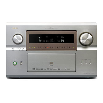
Page 22: Part Names And Functions Front Panel
6 PART NAMES AND FUNCTIONS Front Panel • For details on the functions of these parts, refer to the pages given in parentheses ( ). !6 !7 q w e u i o @3 @4 @5 @9 #0 #1 #7 #9 $1 #6 #8 $0... - Page 23 Power ON/STANDBY switch ..........(120) SYSTEM SETUP button............(26) Power indicator..............(120) CH SELECT/ENTER button........(26, 129, 130) Power switch..............(120, 160) SURROUND PARAMETER button.........(132) Headphones jack (PHONES)..........(125) CINEMA button .............(137, 139) V.AUX INPUT jacks ..............(17) MUSIC button..............(137, 139) SETUP MIC jack ..............(32) GAME button.................(137) USER MODE 1 button............(141) ROOM EQ button..............(125) USER MODE 2 button............(141)
-
Page 24: Display
REC OUT mode is selected in ZONE3/REC SELECT. Information display DENON LINK indicator This displays the surround mode, function name or setting This lights during playback in a DENON LINK connection. value, etc. V.OFF indicator OUTPUT SIGNAL CHANNEL indicator This lights when the operation of the video circuit has been The audio channels that can be output light. -
Page 25: Remote Control Unit
Remote control unit • For details on the functions of these parts, refer to the pages given in parentheses ( ). Remote control signal transmitter..(108) Power buttons........(120) SYSTEM buttons ........(153) Mode selector buttons ......(109) Input source button ......(109) 10KEY/SYSTEM CALL button ....(109) Surround mode button ......(109) SYSTEM buttons ......(109, 110) Cursor buttons........(26) -
Page 26: System Setup
Press this to display the system setup menu. NOTES: • The AVC-A1XV’s on-screen display function is designed for use with high resolution monitor TVs, so it may be difficult to read small characters on TVs with small screens or low resolutions. - Page 27 2. Speaker Setup Speaker Setup Default settings Page Input the combination of speakers in your system and their Surround Back Surround Sp. Front Sp. Center Sp. Subwoofer A / B Speaker corresponding sizes (SMALL for regular speakers, LARGE for full- 46, 47 Configuration size, full-range) to automatically set the composition of the signals...
- Page 28 5. Advanced Playback Advanced Playback Default settings Page The speaker settings can be changed specifically for playing in the 2- Basic Direct/Stereo channel direct or stereo mode. Dolby Digital Turn the audio compression on or off when down-mixing Dolby Setup Digital signals.
-
Page 29: Speaker System Layout
(SL) and surround right (SR), surround back left (SBL) and surround back right (SBR)) is less than 60 cm (2 ft). With the AVC-A1XV it is also possible to use the surround speaker selector function to choose the best layout for a variety of sources and surround modes. -
Page 30: Before Setting Up The System
The AVC-A1XV’s Audyssey MultEQ XT function has the feature that it provides the optimum listening environment at all listening positions in the home theater, where there are often multiple listeners viewing programs together. To achieve this, it is first necessary to use a microphone to measure test tones generated from the different speakers at the various listening positions. -
Page 31: Measurement Flow
2 Measurement flow Connect the microphone to be used for the auto setup procedure. Please place the measuring microphone at ear height at the main listening position. By default, the speaker system setting is set to 9.1 channels. Please set under “Extra Setup”, only when you want to change this arrangement. -
Page 32: Before Performing The Auto Setup Procedure
Some subwoofers have a standby mode. Be sure to turn this function off before performing the Auto Setup procedure. The auto setup procedure uses the OSD (on-screen display) function, so connect the AVC-A1XV to a TV, projector, or other monitor. . Connecting the microphone for Auto Setup Connect the microphone for Auto Setup to the Setup Mic connector on the front panel of the unit. -
Page 33: Auto Setup / Room Eq
Setting the Auto Setup / Room EQ Select “Auto Setup / Room EQ” at the System Setup Menu. CH SEL ENTER * S y s t e m S e t u p A u t o S e t / R o o m E Q (Main unit) (Remote control unit) Display the Auto Setup / Room EQ menu screen. -
Page 34: Extra Setup
. Extra Setup • By default, the speaker system setting is set to 9.1 channels. Perform this setting if you want to change the channel setup to match the speaker system you are using or to conduct the power amplifier assignment procedure. -
Page 35: Preliminary Measurements
. Preliminary measurements • This procedure is used to automatically determine the background noise, whether or not speakers are connected, and the polarities of the connected speakers. Select the “Start” and press the Cursor left button. Start the preliminary measurements. * A u t o S e t u p S t a r t (Main unit) -
Page 36: Speaker System Measurement
. Speaker system measurement • With these measurements, the “Speaker Configuration”, “Delay Time”, “Channel Level”, “Crossover Frequency” and “Room EQ” are analyzed automatically. The main listening position is measured first, so leave the microphone where it is. Select the “OK Start” and press the Cursor left button. - Page 37 After measuring at the number of points according to your listening environment, select “Calculate” and press the Cursor left button. The speaker system is analyzed. (Main unit) (Main unit) 7 t h P o s i t i o n C a l c u l a t e CH SEL ENTER...
-
Page 38: Check Of The Measurement Result
. Check of the measurement result • The results of the measured items can be checked. For instructions on checking the equalizer parameters, see pages 43~45. Select the items. The measurement results of each item can be CH SEL checked here. ENTER * A u t o S e t u p (Main unit) -
Page 39: About The Error Message
• These error messages will be displayed when performing the measurements of Auto Setup and the automatic measurements can not be completed because of the speaker arrangement, measurement environment, or other factors. Please check the following matters, reset the pertinent items, and measure again. Be sure to turn off the AVC-A1XV’s power before checking the speaker connections. Screen example... -
Page 40: Setting The Room Eq Setup
1-2. Setting the Room EQ Setup • Select the setting of an Equalizer that has been set with Auto Setup or Manual EQ. Select “Room EQ Setup” at the Auto Setup / Room EQ menu. CH SEL ENTER * A u t o S e t / R o o m E Q R o o m E Q S e t u p (Main unit) (Remote control unit) -
Page 41: Setting The Direct Mode
Enter the setting. The Auto Setup / Room EQ menu reappears. CH SEL ENTER (Main unit) (Remote control unit) 1-3. Setting the Direct Mode • Perform the ON/OFF setting of Room EQ when the surround mode is Direct or Pure Direct. Select “Direct Mode Setup”... -
Page 42: Setting The Mic Input Select
• Use this setting when using a microphone other than the included one for measurements when performing the auto setup procedure. • The microphone included with the AVC-A1XV is a measurement microphone designed specifically for use during the auto setup procedure. -
Page 43: Check The Parameter
1-5. Check the Parameter • The results of the measured items can be checked. • The EQ parameters that were set in Auto Setup can be checked. • This item is automatically displayed, after the measurement result of the “Auto Setup / Room EQ” is decided. Select “Parameter Check”... - Page 44 Display the parameter screen. The display is only an approximate picture of the CH SEL ENTER response and that correction is happening at all frequencies. (Main unit) (Remote control unit) E Q C h k A u d y s s e y F L / F R : N e x t Select the speaker channel.
-
Page 45: Speaker Setup
Select “Exit” and press the ENTER button at the Parameter Check screen. The Auto Setup / Room EQ menu reappears. * P a r a m e t e r C h e c k (Main unit) (Main unit) E x i t CH SEL CH SEL ENTER... -
Page 46: Setting The Type Of Speakers
2-1. Setting the type of speakers • The composition of the signals output to each channels and the frequency response are adjusted automatically according to the combination of speakers actually being used. Select “Speaker Config.” at the Speaker Setup menu. CH SEL ENTER * S p e a k e r S e t u p... -
Page 47: Setting The Low Frequency Distribution
• Parameters Large.....Select this when using speakers that can fully reproduce deep bass well below 80 Hz. Small ....Select this when using speakers that are not capable of handling deep bass well below 80 Hz. Most home theater main and surround speakers perform best when configured as SMALL. -
Page 48: Setting The Delay Time
NOTES: — Assignment of low frequency signal range (2-1) — • The only signals produced from the subwoofer channel are LFE signals (during playback of Dolby Digital or DTS signals) and the low frequency signal range of channels set to “Small” in the setup menu. The low frequency signal range of channels set to “Large” are produced from those channels. - Page 49 Enter the setting. The Speaker Setup menu reappears. CH SEL ENTER The AVC-A1XV automatically sets the optimum surround delay time for the listening room. (Main unit) (Remote control unit)
-
Page 50: Setting The Channel Level
2-4. Setting the Channel Level • Use this setting to adjust so that the playback level between the different channels is equal. • From the listening position, listen to the test tones produced from the speakers to adjust the level. •... - Page 51 a. When “Auto” mode is selected: Test tones are automatically emitted from each speaker. The test tones are emitted from each speaker in the following order, at 4-second intervals the first time and second time around, 2- second intervals the third time around and on: (Main unit) Flashing 2spkrs...
-
Page 52: Setting The Crossover Frequency
2-5. Setting the Crossover Frequency • Set the crossover frequency according to the low frequency response characteristics of the various (front, center, surround and surround back) speaker systems. • If a connected main or surround loudspeaker has a specified –3 dB low frequency response rolloff, adjust the crossover frequency for that speaker to match the specified low frequency response limit –... -
Page 53: Setting The Crossover Frequency Individually For The Different Channels
2 Setting the crossover frequency individually for the different channels Select “Advanced” at the Crossover Frequency screen. CH SEL ENTER * C r o s s o v e r F r e q A d v a n c e d (Main unit) (Remote control unit) Select the speaker to be set. -
Page 54: Selecting The Surround Speakers For The Different Surround Modes
2-6. Selecting the Surround Speakers for the different surround modes • This menu is displayed when both surround speakers A and B are used. • At this screen preset the surround speakers to be used in each surround modes. Select “Surround Sp Setup” at the Speaker Setup menu. -
Page 55: Setting The Thx Audio Setup
2-7. Setting the THX Audio Setup [1] Settings for using a THX Ultra2 compatible subwoofer • Make these settings when “Yes” is selected for the subwoofer in the “2-1. Speaker Configuration” settings. There is not displayed when “No” selected. (pages 46, 47) Select “THX Audio Setup”... -
Page 56: Surround Back Speaker Position Settings
[2] Surround Back Speaker Position Settings • When two surround back speakers have been set in “2-1. Speaker Configuration” (pages 46, 47), set the distance of the speakers. There is not displayed when “1spkr” selected. • This setting is necessary to achieve the optimum effect in the THX Surround EX, THX Ultra2 Cinema, THX Music modes and THX Games mode. -
Page 57: Audio Input Setup
D i g i t a l I n (Main unit) (Remote control unit) 3-1. Setting the Digital In Assignment • This setting assigns the digital input jacks of the AVC-A1XV for the different input sources. Select “Digital In Assign” at the Audio Input Setup menu. CH SEL... - Page 58 (stereo - 2 channel) and a digital audio recorder. • Do not connect the output of the component connected to the OPTICAL 3 OUT jack on the AVC-A1XV’s rear panel to any jack other than the OPTICAL 3 IN jack.
-
Page 59: Setting The Ext.in Setup
3-2. Setting the EXT. IN Setup • Set the method of playback of the analog input signal connected to the EXT.IN-1 (10 CH) and EXT.IN-2 (6 CH) terminal. Select “EXT.IN Setup” at the Audio Input Setup menu. CH SEL ENTER * A u d i o I n S e t u p E X T . -
Page 60: Setting The Ext.in Setup
• The items to be set differ as described below according to the selected input jack and the “Mode” selection. EXT. IN-1 (10 CH) EXT. IN-2 (6 CH) Mode ANALOG ANALOG Surr. B NOT USED / USED NOT USED / USED –... -
Page 61: Setting The Input Function Level
3-3. Setting the Input Function Level • Correct the playback level of the different input sources. • Adjust the playback levels of the devices connected to the different input sources to the same level to eliminate the need for adjusting the main volume each time the input source is switched. -
Page 62: Setting The Function Rename
3-4. Setting the Function Rename • The names of the input sources displayed on the front display and on the on-screen display can be changed. The names or brands of the devices connected to the input sources can be input. Select “Function Rename”... - Page 63 Repeat step 5 to input the input source name. If you wish to set the input source back to as it was initially, press the Cursor down button with the input source highlighted. If “Yes” is selected for “Default”, the setting are automatically reset to the default name. R e n a m e T U N E R R e n a m e C l e a r...
-
Page 64: Setting The Ieee1394 Assign
If you do not wish to assign the device connected by IEEE1394 cable to an input source, the IEEE1394 input can be selected by turning the FUNCTION knob. In this case, the connection information is cleared when the power of the connected device or the AVC-A1XV is turned off, so the selection procedure must be performed again. -
Page 65: Selecting The Ieee1394 Auto Function
3-6. Setting the IEEE1394 Auto Function • Set whether or not to automatically play the IEEE1394 device when it is selected with the FUNCTION knob. Select “IEEE1394 Auto Func.” at the Audio Input Setup menu. CH SEL ENTER * A u d i o I n S e t u p I E E E 1 3 9 4 A u t o (Main unit) (Remote control unit) -
Page 66: Video Setup
C o m p o n e n t I n (Main unit) (Remote control unit) 4-1. Setting the Component In Assign • This setting assigns the component video input terminal of the AVC-A1XV for the different input sources. Select “Component In Assign” at the Video Setup menu. CH SEL... -
Page 67: Setting The Video Convert Mode
Enter the setting. The Video Setup menu reappears. CH SEL ENTER (Main unit) (Remote control unit) 4-2. Setting the Video Convert Mode • Select the input signal to be output to the composite S-Video and component monitor output terminals using the video conversion function. Select “Video Convert Mode”... -
Page 68: Setting The Video Scaler
Enter the setting. The Video Setup menu reappears. CH SEL ENTER (Main unit) (Remote control unit) NOTES: • When a non-standard video signal from a game machine or some other source is input, the video conversion function might not operate. If this happens, please set the conversion mode to OFF. -
Page 69: Setting The 3D Y/C Separation
Enter the setting. The Video Setup menu reappears. CH SEL ENTER (Main unit) (Remote control unit) NOTES: • When the component video input signal is a resolution other than 480i/576i, this setting is invalid and the input video is output without change. -
Page 70: Setting The Hdmi/Dvi In Assign
4-5. Setting the HDMI / DVI In Assign • This setting assigns the HDMI input terminals and DVI input terminal for different input sources. • Select which input signal, HDMI or DVI, is to be output from which monitor out jack, HDMI or DVI. •... -
Page 71: Setting The Audio Delay
A1XV (DVI mode). Use the STATUS button to check which mode is set for outputting HDMI signals from the AVC-A1XV (HDMI and DVI modes). Select the input for the playback of signals when the audio signal of HDMI can not be reproduced. -
Page 72: Setting The On Screen Display (Osd)
Set the delay time. (0 ms ~ 200 ms) With a movie source, for example, adjust so that the movement of the actors’ lips is CH SEL ENTER synchronized with the sound. (Main unit) (Remote control unit) Enter the setting. The Video Setup menu reappears. -
Page 73: Advanced Playback
Enter the setting. The Video Setup menu reappears. CH SEL ENTER (Main unit) (Remote control unit) Select “Exit” and press the ENTER button at the Video Setup menu screen. The System Setup Menu reappears. * V i d e o S e t u p (Main unit) (Main unit) E x i t... -
Page 74: Setting The 2Ch Direct/Stereo
5-1. Setting the 2ch Direct/Stereo • Set this when you want to change the speaker settings when the surround mode is set to the 2-channel Direct or Stereo mode. Select “2ch Direct / Stereo” at the Advanced Playback menu. CH SEL ENTER * A d v a n c e d P l a y 2 c h D R C T / S T... -
Page 75: Setting The Dolby Digital Setup
5-2. Setting the Dolby Digital Setup Sets the down-mixing method when not using a center speaker or surround speakers. OFF: The dynamic range is not compressed. The dynamic range is compressed automatically according to the combination of speakers being used. Select “Dolby Digital Setup”... -
Page 76: Setting Auto Surround Mode
5-3. Setting the Auto Surround Mode The surround mode used at last for the four types of input signals shown below is stored in the memory, and the signal is automatically played with that surround mode the next time it is input. Note that the surround mode setting is also stored separately for the different input sources. -
Page 77: Setting The Manual Eq Setup
5-4. Setting the Manual EQ Setup • Allows you to adjust the tonal quality of the various speakers (except the subwoofer) while listening to a music source. Select “Manual EQ Setup” at the Advanced Playback menu. CH SEL ENTER * A d v a n c e d P l a y M a n u a l E Q S e t u p (Main unit) (Remote control unit) - Page 78 Select the frequency. CH SEL ENTER * M a n u a l E Q : L / R 6 3 H z : 0 . 0 d B (Main unit) (Remote control unit) Use the Cursor left and right buttons to adjust the Gain level. •...
-
Page 79: Procedure For Copying The "Flat" Correction Curve
2 Procedure for copying the “Flat” correction curve set at “Auto Setup”, then using the graphic equalizer to adjust manually NOTE: If the “Auto Setup” procedure has not been performed, this item is not displayed. Select “Base Curve Copy”. CH SEL ENTER * M a n u a l E Q B a s e C u r v e C o p y... -
Page 80: Zone Setup (Zone2 = 5.1/7.1Ch)
Setting the Zone Setup (ZONE2 = 5.1/7.1ch) • Make the settings related to surround playback and video for ZONE2. • Adjust the sound played in ZONE3 and ZONE4. Select “Zone Setup” at the System Setup Menu. CH SEL ENTER * S y s t e m S e t u p Z o n e S e t u p (Main unit) (Remote control unit) -
Page 81: Setting The Type Of Speakers For Zone2
6-1. Setting the type of speakers for ZONE2 • The composition of the signals output to each channels and the frequency response are adjusted automatically according to the combination of speakers actually being used in ZONE2. Select “Speaker Config.” at the Zone Setup menu. CH SEL ENTER * Z o n e S e t u p... -
Page 82: Setting The Low Frequency Distribution For Zone2
6-2. Setting the low frequency distribution for ZONE2 • Set the subwoofer mode according to the speaker systems used in ZONE2. Select “Subwoofer Mode” at the Zone Setup menu. CH SEL ENTER * Z o n e S e t u p Z 2 S W M o d e (Main unit) (Remote control unit) -
Page 83: Setting The Delay Time For Zone2
6-3. Setting the Delay Time for ZONE2 • Input the distance between the listening position and each speakers in ZONE2 to set the surround delay time for ZONE2. Select “Delay Time” at the Zone Setup menu. CH SEL ENTER * Z o n e S e t u p Z 2 D e l a y T i m e (Main unit) (Remote control unit) - Page 84 Enter the setting. The Zone Setup menu reappears. CH SEL ENTER The AVC-A1XV automatically sets the optimum surround delay time for the ZONE2 listening room. (Main unit) (Remote control unit)
-
Page 85: Setting The Channel Level For Zone2
6-4. Setting the Channel Level for ZONE2 • Use this setting to adjust so that the playback level between the different channels of ZONE2 is equal. • From the ZONE2 listening position, listen to the test tones produced from the speakers used in ZONE2 to adjust the level. •... - Page 86 a. When “Auto” mode is selected: Test tones are automatically emitted from each speaker used in ZONE2. The test tones are emitted from each speaker in the following order, at 4-second intervals the first time and second time around, 2- second intervals the third time around and on: (Main unit) Flashing...
-
Page 87: Setting The Crossover Frequency For Zone2
6-5. Setting the Crossover Frequency for ZONE2 • Set the frequency (in Hz) below which deep bass appearing in the main channels will be routed to the ZONE2 subwoofer. Select the “Crossover Frequency” at the Zone Setup menu. CH SEL ENTER * Z o n e S e t u p Z 2 C r o s s o v e r... -
Page 88: Setting The Video Setup For Zone2
6-6. Setting the Video Setup for ZONE2 [1] Video Convert Mode (ZONE2) • Select the video input signal to be output to the ZONE2 composit, S-Video and component monitor output terminals using the video conversion function. Select “Video Setup” at the Zone Setup menu. CH SEL ENTER * Z o n e S e t u p... -
Page 89: Audio Delay
Press the ENTER button to return to the Video Setup screen. CH SEL ENTER (Main unit) (Remote control unit) [2] Audio Delay (ZONE2) • Set this if it seems there is a delay in the picture on the monitor screen with respect to the sound when watching a DVD or other video source in the ZONE2 listening room. -
Page 90: Zone3 And Zone4 Tone Control And Channel Level Setting
6-7. ZONE3 and ZONE4 tone control and channel level setting • Adjust the sound output from ZONE3 and ZONE4. Select “Zone3/4 Tone/Ch Lev.” at the Zone Setup menu. CH SEL ENTER * Z o n e S e t u p Z o n e 3 / 4 (Main unit) (Remote control unit) -
Page 91: Zone Setup Setting When Zone2 Is Set To Stereo Or Mono
Select “Exit” then press the ENTER button. The Zone Setup menu reappears. * Z o n e 3 / 4 E x i t (Main unit) (Main unit) CH SEL CH SEL ENTER ENTER (Remote control unit) (Remote control unit) Select “Exit”... -
Page 92: Option Setup
• With this setting it is possible to change the number of channels played in the different zones according to the purpose. The AVC-A1XV is equipped with pre-out connectors for a total of 22 channels. 16 channel of these pre-out connectors can be assigned between the MAIN ZONE and ZONE2 (Theater). In addition, up to three channels of subwoofers can be added to the MAIN ZONE, so subwoofers can be set in the front and back or at the sides. - Page 93 Select “Channel Setup” at the Option Setup menu. CH SEL ENTER * O p t i o n S e t u p C h a n n e l S e t u p (Main unit) (Remote control unit) Display the Channel Setup screen.
-
Page 94: The Number Of Channels That Can Be Selected
2 The number of channels that can be selected for the different zones is as shown below. MAIN ZONE ZONE2 ZONE3 ZONE4 Main Subwoofer 9.1 CH 1 SP 5.1 CH / STEREO / MONO STEREO / MONO STEREO / MONO 2 SP STEREO / MONO STEREO / MONO... -
Page 95: Connecting The Preouts
2 Connecting the preouts The pre-out connector used to connect the subwoofer depends on the MAIN ZONE’s channel setup. Connect as shown on the diagram below. Channel Setup Connection Main Subwoofer 9.1 CH / 7.1 CH / 1 SP 5.1 CH Subwoofer 9.1 CH 2 SP... -
Page 96: Setting The Power Amplifier Assignment
This makes it possible to put together various speaker systems. The channels can be selected freely, so “L1” to “L5” and “R1” to “R5” are indicated on the speaker terminals on the AVC-A1XV’s rear panel. - Page 97 Select “Power Amp Assign” at the Option Setup menu. CH SEL ENTER * O p t i o n S e t u p P . A m p A s s i g n (Main unit) (Remote control unit) Display the Power Amp Assign screen.
-
Page 98: Amp Assign Mode
5 bi-amplified speakers in a system using all 10 of the AVC-A1XV amplifier channels. Be sure to consult the owner’s manual of your bi-amp-capable speakers for further information before proceeding. - Page 99 • Amp Assign mode: +Zone2 MAIN ZONE 9.1 CH 7.1 CH 5.1 CH Channel Setup / ZONE2 MONO STEREO MONO 5.1 CH STEREO MONO Power Amp Assign R2 Z2 M – R2 Z2 M R2 Z2 C – R2 Z2 M L3 SL A R3 SR A L3 SL A R3 SR A L3 SL A R3 SR A...
-
Page 100: Table Of Channels To Which Power Amplifiers Can Be Assigned
• Amp Assign mode: +Zone2/3/4 MAIN ZONE 7.1 CH 5.1 CH ZONE2 MONO STEREO STEREO MONO STEREO MONO MONO MONO Channel Setup / ZONE3 MONO STEREO MONO STEREO MONO STEREO MONO MONO ZONE4 MONO MONO STEREO STEREO MONO MONO STEREO MONO Power Amp Assign R2 Z2 M... -
Page 101: Setting The Volume Control
LAST : The volume set when the AVC-A1XV was last used is stored in the memory and set when the power is turned Mute Level: Set the volume attenuation level when the mute mode is set for the different zones. -
Page 102: Setting The Trigger Out
Enter the setting. The Option Setup menu reappears. CH SEL ENTER (Main unit) (Remote control unit) 7-4. Setting the Trigger Out • Four 12 V DC Trigger Outputs on the rear panel can be used to control other devices with compatible trigger inputs, such as motorized screens, motorized screen masking, motorized drapes, and other trigger-controlled devices. - Page 103 If “MAIN” was selected at step 4, the trigger out jack’s output setting can also be made for the * T r i g g e r O u t 1 various surround modes. D R C T / S T : O N q Select the surround mode.
-
Page 104: Setting The Ac Outlet Assign
7-5. Setting the AC Outlet Assign • Set the power of the AC outlet on the AVC-A1XV’s rear panel to ON or OFF with respect to the different input sources. Select “AC Outlet Assign” at the Option Setup menu. CH SEL... -
Page 105: Protecting The Setting And Memory Backup [1] User Memory
7-6. Protecting the setting and memory backup [1] User Memory • The currently set settings (system setup, surround parameters, etc.) can be stored in the memory. The stored settings can be called out when needed. Select “Setup Memory / Lock” at the Option Setup menu. -
Page 106: Setup Lock
Select “Exit” and press the ENTER button to return to the Setup Memory / Lock screen. (Main unit) (Main unit) CH SEL CH SEL ENTER ENTER (Remote control unit) (Remote control unit) [2] Setup Lock • The system setup settings can be locked so that they cannot be changed easily. Select “Setup Lock”... -
Page 107: After Completing System Setup
“Surround Parameter” operations are performed and when the Remote control unit’s ON SCREEN button is operated. • When only component video signals are input to the AVC-A1XV or when “Component” is selected at the “Video Convert Mode settings”, the... -
Page 108: Remote Control Unit
8 REMOTE CONTROL UNIT • The included Remote control unit (RC-995) can be used to operate not only the AVC-A1XV but other remote control compatible DENON components as well. In addition, the memory contains the control signals for other Remote control units, so it can be used to operate non- Denon remote control compatible products. -
Page 109: Operating Denon Audio Components
Operating DENON audio components Use the mode selector buttons to select the component you want to operate. The function switches as shown below each time one of the mode buttons is pressed. AMP/Z2 : AMP, ZONE2 Z3/Z4 : ZONE3, ZONE4... - Page 110 2. CD recorder (CDR), MD recorder (MD), Tape deck (TAPE) 3. Tuner system buttons system buttons : Manual search (forward and reverse) •, ª : Tuning up/down : Stop BAND : Switch between AM and FM bands : Play MODE : Switch between AUTO and MANUAL : Auto search (to beginning of track) : Preset memory...
-
Page 111: Preset Memory
The preset codes are as follows upon shipment from the factory and the component whose signals you after resetting: want to store in the memory. TV, VCR1 ..............HITACHI CD, CDR, VDP, DVD, DVDR ........DENON VCR2, DBS..............SONY DVD preset codes 0000 (default) 0517 DENON Model No. -
Page 112: Operating A Component Stored In The Preset Memory
1. DVD player (DVD), DVD recorder (DVD R) system buttons 2. Video disc player (VDP) system buttons SRC ON : Power on : Power off (DENON DVD only) : Manual search (forward and reverse) : Stop : Play : Auto search... - Page 113 3. Video deck (VCR-1/VCR-2) system buttons 4. Monitor TV (TV),digital broadcast satellite (DBS) tuner and cable (CABLE) system buttons RC-995 RC-995 SRC ON : Power on/Standby SRC ON : Power on/standby : Manual search (forward and reverse) SETUP : Setup : Stop : Top menu : Play...
-
Page 114: Learning Function
Learning function If an AV component is not a DENON product, or if it cannot be operated via codes provided in the AVC-A1XV remote control’s internal preset memory, or if its codes cannot be successfully learned by the AVC-A1XV remote control, then you should use the remote control that was supplied with that AV component to operate the component. -
Page 115: System Call
System call The accessorious Remote control unit is equipped with “system call” function allowing a series of remote control signals to be transmitted by pressing a single button. This function can be used for example to turn on the amplifier’s power, select the input source, turn on the monitor TV’s power, turn on the source component’s power and set the source to the play mode, all at the touch of a single button. -
Page 116: Punch Through
NOTES: • The remote control signals of the buttons pressed while registering the system call signals are emitted, so be careful not to operate the components accidentally (cover the remote sensors, for example). • If you exceed the number of signals that can be registered, there will be a changeover to the System Call registration screen. (3) Using the system call function Press the button at which the system call signals have been stored. -
Page 117: Setting The Back Light's Lighting Time
Setting the back light’s lighting time Press the power ON button and the OFF button at the same time. Press the “5” button to select Light setup. 2, 3 Press the button you want to adjust the lighting time (5 sec ~ 20 sec). •... -
Page 118: Resetting
Resetting (1) Resetting the preset memory Press the power ON button and the OFF button at the same time. Press the “6” button to select Resetting. 2, 3 Press the “1” button to resetting the preset memory. • Resetting List Resetting the preset memory Resetting the “Learned”... -
Page 119: Resetting
(2) Resetting “learned” buttons (4) Resetting the punch through setting Press the power ON button and the OFF button at the same Press the power ON button and the OFF button at the same time. time. Press the “6” button to select resetting. Press the “6”... -
Page 120: Operation
9 OPERATION Operating the Remote control unit Select “AMP” using the AMP/Z2 button. [SOURCE MENU] [SURROUND MENU] • Operate the source. • Operate the surround mode. Before operating Refer to “CONNECTIONS” (pages 9 to 21) and check that all connections are correct. Press the POWER switch (button). -
Page 121: Playing The Input Source
• Selecting the external input (EXT. IN) mode the program in the AVC-A1XV’s surround decoder is selected Press the EXT. IN (on the EXT. IN button on the Remote automatically upon playback. - Page 122 • DTS Depending on the input signal. (Main unit) (Remote control unit) • The indicator lights when the DENON LINK • PCM have been connected and the DSD signals have been inputted. (See page 18) M.VOL. -80.0dB Depending on the input signal.
-
Page 123: Playback Using External Input (Ext.in) Jacks
Playback using the external input (EXT. IN) jacks Set the external input (EXT. IN) mode. Press the EXT. IN button (on the Remote control unit) to switch the external input. The playback switches as shown below (Main unit) each time the button is pressed. EXT. -
Page 124: Playing Audio Sources (Cds And Dvds)
With discs on which special copyright protection measures have been taken, however, the digital signals may not be output from the DVD player. In this case, connect the DVD player’s analog multi-channel output to the AVC-A1XV’s EXT. IN-1 or EXT. IN-2 terminals for playback. -
Page 125: After Stating Playback
After starting playback [1] Setting the Room EQ The Room EQ switches as follows each time the ROOM EQ button is pressed. (Main unit) (Remote control unit) Audyssey Front Flat Manual See pages 30, 40 for descriptions of the correction curves for the “Room EQ”... -
Page 126: Checking The Currently Playing Program Source, Etc
On screen display Each time an operation is performed, a description of that operation appears on the display connected to AVC-A1XV’s VIDEO MONITOR OUT jack. Also, the unit’s operating status (Remote control unit) can be checked during playback by pressing the Remote control unit’s... -
Page 127: Selection Of Resolution Setting (Scale)
[8] Selection of resolution setting (SCALE) The resolution switches as follows each time the SCALE button is pressed. (Main unit) (Remote control unit) 480i/576i 480p/576p 1080i 720p See page 68 for descriptions of the different resolution settings. RC-995 Multi-source recording/playback [1] Playing one source while recording another (REC OUT mode) Press the ZONE3/4/REC SELECT button 2,4 1... -
Page 128: Recording Dolby Digital And Dts Multichannel Sources
RC-995 [3] Dolby Headphone recording • When RECOUT mode is set to “source”, with the AVC-A1XV it is possible to output signals encoded in the Dolby Headphone mode from the recording output terminal and record them on a separate recorder. -
Page 129: Surround
10 SURROUND Adjustment steps that need to be performed prior to surround sound playback If the Auto Setup procedure has not been performed or the channel level has not been adjusted at the System Setup Menu, the settings below cannot be made. [1] Test Tone •... -
Page 130: Fader Function
Ajust the level of the selected speaker. • The adjustment range for the different channels is +12 dB to –12 dB in step of 0.5 dB. • The sound from the subwoofer can be completely cut by lowering the SW (subwoofer) setting CH SEL ENTER one additional from –12 dB (setting it to “OFF”). -
Page 131: Playing Modes For Different Sources
Playing modes for different sources The AVC-A1XV is equipped with many surround modes. We recommend using the surround modes as described below in order to achieve the maximum effect for the specific signal source. is a 6.1-channel/7.1-channel surround mode. THX SURROUND EX Sources recorded in •... -
Page 132: Thx Surround Ex / Home Thx Cinema Mode
THX Surround EX / Home THX Cinema mode When the HOME THX CINEMA button is pressed, the surround mode is set as follows according to the signal that is played: q THX Surround EX (THX Ultra2 Cinema) w Home THX CINEMA e THX 5.1 r THX DSCRT 6.1, THX MTRX 6.1 When the HOME THX CINEMA mode is set when a DVD is played, check the DVD player’s digital output setting and change the setting to one... - Page 133 q Select the parameter. w Select the setting. CH SEL CH SEL ENTER ENTER (Main unit) (Remote control unit) (Main unit) (Remote control unit) Press the ENTER or SURROUND PARAMETER button to complete the setting. CH SEL ENTER (Main unit) (Remote control unit) Surround parameters q DECODER:...
-
Page 134: To Play In The Thx Surround Ex/Home Thx Cinema Surround Mode For Sources Recorded In Dolby Digital Or Dts
[2] To play in the THX Surround EX/Home THX Cinema Surround mode for sources recorded in Dolby Digital or DTS Select the program source. Selecting a digital input source Perform step 1 under “Dolby Digital mode and DTS Surround” (page 135). Select the Home THX Cinema mode. - Page 135 Dolby Digital mode (only with digital input) and DTS Surround (only with digital input) Select the input source. Playback with digital input q Select an input source set to digital (COAXIAL/OPTICAL) (see pages 57, 58). (Main unit) (Remote control unit) w Set the input mode to “AUTO”.
- Page 136 Display the Surround Parameter menu. (Main unit) (Remote control unit) q Select the parameter. w Select the setting. CH SEL CH SEL ENTER ENTER (Main unit) (Remote control unit) (Main unit) (Remote control unit) Press the ENTER or SURROUND PARAMETER button to complete the setting.
-
Page 137: Dolby Pro Logic Ii X (Dolby Pro Logic Ii ) Mode
Dolby Pro Logic x (Pro Logic ) mode To play in the PL x mode, set “Sp.Back” at the Speaker Configuration setting to “1Spkr” or “2spkrs”. To play in the PL x mode, set “Surround Back” at the Power Amp Assign setting. The Dolby Surround Pro Logic x Cinema, Music or... - Page 138 (Remote control unit) NOTE: • There are four Dolby Surround Pro Logic modes (NORMAL, PHANTOM, WIDE and 3 STEREO). The AVC-A1XV sets the mode automatically according to the types of speakers set during the system setup process (pages 46, 47).
-
Page 139: Dts Neo:6 Mode
DTS NEO:6 mode • Surround playback can be performed for the analog input and digital input 2-channel signals. The DTS NEO:6 Cinema or Music mode can be chosen directly by pressing the Select the DTS NEO:6 mode. CINEMA or MUSIC button on the Remote control unit during playback in the DTS NEO:6 mode. -
Page 140: The Dolby Headphone
Press the ENTER or SURROUND PARAMETER button to complete the setting. CH SEL ENTER (Main unit) (Remote control unit) NOTE: • When “Default” is selected and the Cursor left button is pressed, “MODE” and “TONE” are automatically reset to the default values and “CINEMA EQ”... -
Page 141: Memory And Call-Out Functions (User Mode Function)
Memory and call-out functions (USER MODE function) • The AVC-A1XV is equipped with a function for storing the selected input source, the auto surround mode and input mode in the memory and selecting these settings when you want to use them. -
Page 142: Denon Original Surround Modes
11 DENON ORIGINAL SURROUND MODES • The AVC-A1XV is equipped with a high performance DSP (Digital Signal Processor) which uses digital signal processing to synthetically recreate the sound field. One of ten preset surround modes can be selected according to the program source and the parameters can be adjusted according to the conditions in the listening room to achieve a more realistic, powerful sound. -
Page 143: Dsp Surround Simulation
DSP surround simulation Select the surround mode for each input channel. (Main unit) (Remote control unit) (Remote control unit) The surround mode switches in the following order each time the DSP SIMULATION button is pressed: WIDE SCREEN SUPER STADIUM ROCK ARENA JAZZ CLUB MATRIX VIDEO GAME... -
Page 144: Tone Control Setting
NOTES: • The surround speaker setting can also be changed with the SPEAKER button on the Main unit or Remote control unit. • When “Default” is selected and the Cursor left button is pressed, “CINEMA EQ.” and “D.COMP.” are automatically turned off, “ROOM SIZE”... -
Page 145: Adjusting The Tone From The Main Unit
q Select Bass or Treble. w Set the level. CH SEL CH SEL ENTER ENTER (Remote control unit) (Remote control unit) Enter the setting. The Surround Parameter menu screen re-appears. CH SEL ENTER (Remote control unit) Press the ENTER or SURROUND PARAMETER button to complete the setting. CH SEL ENTER (Remote control unit) -
Page 146: Multi Zone
This parameter for reducing the level of the subwoofer channel when playing in the EXT. IN input mode has been added. Depending on the player you are using, the dubwoofer channel’s playback level may seem too high. If so, set “SW ATT” to “ON”. For Denon players, use with the default settings. Subwoofer ON/OFF: The subwoofer output can be controlled directly. -
Page 147: Zone2 Playback
MULTI ZONE MUSIC ENTERTAINMENT SYSTEM [1] ZONE2 playback The AVC-A1XV is equipped with pre-out terminals for which the volume is adjustable and video output terminals (composite, S-Video and component) as the ZONE2 output terminals. A separately sold power amplifier or premain amplifier can be connected to enjoy ZONE2 playback. - Page 148 • 7.1 channel playback is possible in ZONE2 if “7.1CH” is selected for the ZONE2 channel setting at “7-1. Channel Setup” in the System Setup Menu. MAIN ZONE 7.1-channel system ZONE2 7.1-channel system Monitor Monitor ZONE2 VIDEO OUT DVD player AVC-A1XV Power amplifier ZONE2 AUDIO OUT Input (VARIABLE OUT) ZONE2 VIDEO signal cable MULTI SOURCE AUDIO signal cable VIDEO...
- Page 149 • When only one speaker is being used in ZONE2, select “MONO” for the ZONE2 channel setting at “7-1. Channel Setup” in the System Setup Menu. In this case, monaural sound can be enjoyed in ZONE2. MAIN ZONE 9.1-channel system ZONE2 STEREO/MONO system Monitor Monitor DVD player AVC-A1XV Power amplifier ZONE2 VIDEO OUT Input ZONE2 AUDIO OUT (VARIABLE OUT)
-
Page 150: Zone3 Playback
[2] ZONE3 playback The AVC-A1XV is equipped with pre-out terminals for which the volume is adjustable and video output terminals (composite and S-Video) as the ZONE3 output terminals. 2 ZONE3 STEREO/MONO system • Stereo and monaural sound can be enjoyed in ZONE3. (By default, “STEREO” is selected.) •... -
Page 151: Zone4 Playback
[3] ZONE4 playback The AVC-A1XV is equipped with pre-out terminals for which the volume is adjustable as the ZONE4 output terminals. 2 ZONE4 STEREO/MONO system • Stereo and monaural sound can be enjoyed in ZONE4. (By default, “STEREO” is selected.) •... -
Page 152: Outputting A Program Source To Amplifier, Etc., In A Zone2 Room (Zone2 Select Mode)
[4] Outputting a program source to an amplifier, etc., in a ZONE2 room (ZONE2 SELECT mode) Press the ZONE2 SELECT button. (Main unit) Select the source you want to output appears on the set’s display. (Main unit) Start playing the source to be output. •... -
Page 153: Remote Control Unit Operations During Multi-Source Playback
Each time an operation is performed, a description of that operation appears on the display connected to AVC-A1XV’s ZONE2 MONITOR OUT jack. Also, the unit’s operating status can be checked during playback by pressing the Remote control unit’s ON SCREEN button. -
Page 154: System Setup For Multi-Zone
System setup for multi-zone • This makes it possible to make the optimum setting for the speaker systems used in ZONE2. Select the ZONE2 mode using the AMP/Z2 button. (Remote control unit) Press the SYSTEM SETUP button and display the ZONE2 System Setup Menu. -
Page 155: Channel Level
[2] Channel Level • After adjusting using the test tones, adjust the channel levels either according to the playback sources or to suit your tastes, as described below. Select the ZONE2 mode using the AMP/Z2 button. (Remote control unit) The channel Volume is displayed at ZONE2 monitor out. -
Page 156: Fader Function
Fader function • This function makes it possible to lower the volume of the front channels (FL, C and FR) or the rear channels (SL, SR, SBL and SBR) of ZONE2 together. Use it for example to adjust the balance of the sound from each position when multi-channel music sources are played. Select the ZONE2 mode using the AMP/Z2 button. -
Page 157: Zone2 Surround
ZONE2 Surround • When ZONE2 is used with a 5.1- or 7.1-channel system, various surround modes can be selected according to the program source being played. • The desired sound field can be achieved by adjusting the parameters for the various surround modes. Select the ZONE2 mode using the AMP/Z2 button. -
Page 158: Memory And Call-Out Functions Of Zone2 (User Mode Function)
Memory and call-out functions of ZONE2 (USER MODE function) • The AVC-A1XV is equipped with a function for storing the input source, auto surround mode and input mode settings selected for the MAIN ZONE and ZONE2 in the memory so they can be used whenever desired. -
Page 159: Zone2 Tone Control Setting
ZONE2 tone control setting • This function allows you to adjust the bass and treble of the ZONE2 audio output during surround playback in ZONE2 to suit your tastes. Select the ZONE2 mode using the AMP/Z2 button. (Remote control unit) Press the SURROUND PARAMETER button. -
Page 160: Last Function Memory
14 INITIALIZATION OF THE MICROPROCESSOR In very rare instances, the AVC-A1XV internal microprocessor might lock up, or otherwise cause mis-operation. This might be caused due to an AC line surge or line spike noise, or by static electric discharge on or nearby the unit, or to connected components. If the condition cannot be corrected by powering off the unit, including disconnection of the AC cord for a period of ten minutes and subsequent re-connection, then the unit may have to be re-initialized. -
Page 161: Troubleshooting
• No HDMI/DVI-D signal is being input. • Properly select HDMI or DVI-D signal input source. 70, 71 • The connected monitor equipment or other • The AVC-A1XV will not output video signal unless 14, 15 equipments do not spport HDCP. the other equipment supports HDCP. -
Page 162: Additional Information
The AVC-A1XV’s surround speaker selection function makes it possible to change the settings according to the combination of surround speakers being used and the surrounding environment in order to achieve the ideal surround sound for all sources. This means that you can connect a pair of bipolar or dipolar surround speakers (mounted on either side of the prime listening position), as well as a separate pair of direct radiating (monopolar) speakers placed at the rear corners of the listening room. -
Page 163: Surround Back Speakers
Movement of acoustic image from SR to SB to SL Speaker(s) for one or two channels are required in order to achieve a THX Surround EX system with the AVC-A1XV. Adding these, however, allows you to achieve stronger surround effects not only with sources recorded in THX Surround EX, but also with conventional 2- to 5.1-channel sources. -
Page 164: Speaker Setting Examples
• Connect the surround speakers to the surround speaker A jacks on the AVC-A1XV and set settings on the setup menu to “A”. (This is the factory default setting. For details, see page 27.) -
Page 165: When Not Using Surround Back Speakers
45° ~ 60° • Connect the surround speakers for watching movies to the surround speaker A jacks on the AVC-A1XV, Surround the surround speakers for playing multi-channel music to the surround speaker B jacks. Set the surround speakers A speaker selection on the setup menu. -
Page 166: Surround
Surround The AVC-A1XV is equipped with a digital signal processing circuit that lets you play program sources in the surround mode to achieve the same sense of presence as in a movie theater. [1] Dolby Surround q Dolby Digital Dolby Digital is the multi-channel digital signal format developed by Dolby Laboratories. -
Page 167: Dts Digital Surround
• Dolby Headphone is effective not only for multichannel sources but also for stereo programs. • On the AVC-A1XV, it is possible to output signals encoded in the Dolby Headphone mode from the recording output terminal and record them on a separate recorder. -
Page 168: Dts-Es Extended Surround
In this case the DTS-encoded signals may be processed erroneously, in which case they cannot be decoded by the AVC-A1XV, or may only produce noise. Before playing DTS signals for the first time, turn down the master volume to a low level, start playing the DTS disc, then check whether the DTS indicator on the AVC-A1XV (see page 135) lights before turning up the master volume. -
Page 169: Dts 96/24
THX engineers developed patented technologies to accurately translate the sound from the movie theater environment into the home, correcting the tonal and spatial errors that occur. On the AVC-A1XV, when the Home THX Cinema mode is on, THX post-processing is... -
Page 170: Thx Surround Ex
Upon playback, the signals are decoded by a high precision digital matrix decoder within the Dolby Digital decoder into the SL, SR and SB channels and output as 6.1 channels of signals. With the AVC-A1XV, the signals further undergo Home THX Cinema processing to achieve a THX Surround EX system. -
Page 171: Audyssey Multeq Xt
Audyssey MultEQ XT There are several factors that can degrade the sound from even the best loudspeakers in a listening room. One of the most important is the interaction of sound from the loudspeakers with large surfaces such as walls, the floor, and the ceiling in the room. Even with careful loudspeaker placement and acoustical treatments, there are significant problems that are caused by room acoustics. -
Page 172: Denon Link
DENON LINK (DENON Digital Link) High-grade LPCM 24-bit, 96-kHz, 6-channel or 24-bit, 192-kHz, 2-channel digital input is possible when the AVC-A1XV is connected via a shielded twisted pair (STP) cable to a Denon DVD player that supports Denon Digital Link, Since Denon Digital Link uses low-voltage differential signaling (LVDS), transfer capabilities of greater than 1.2 Gbps at a differential voltage of approximately 0.3Vpp are possible. -
Page 173: Surround Modes And Parameters
Surround modes and parameters Signals and adjustability in the different modes Channel output Parameter (default values are shown in parentheses) When playing Dolby Digital and DTS signals SB CH OUT SURROUND SURROUND SUB- TONE D. COMP AFDM FRONT L/R CENTER Mode (MODE) L/R (A/B) - Page 174 Differences in surround mode names depending on the input signals Input signals Surround Mode DOLBY DIGITAL D. D. (5.1 ch) ANALOG LINEAR PCM DTS (5.1 ch) DTS 96/24 (5.1 ch) DTS (6.1 ch) D. D. (2 ch) PURE DIRECT, DIRECT STEREO HOME THX CINEMA x C+THX...
-
Page 175: Relationship Between The Video Input Signal And Monitor Output (Main Zone)
Relationship between the video input signal and monitor output according to the VIDEO CONVERT MODE settings of MAIN ZONE Input signals MONITOR OUT VIDEO CONVERT VIDEO SCALER Mode setting COMPONENT S-VIDEO VIDEO COMPONENT S-VIDEO VIDEO – VIDEO VIDEO VIDEO – S-VIDEO S-VIDEO S-VIDEO... -
Page 176: Relationship Between The Video Input Signal And Monitor Output (Zone2)
Relationship between the video input signal and monitor output according to the VIDEO CONVERT MODE settings of ZONE2 Input signals MONITOR OUT VIDEO CONVERT Mode COMPONENT S-VIDEO VIDEO COMPONENT S-VIDEO VIDEO VIDEO VIDEO VIDEO S-VIDEO S-VIDEO S-VIDEO S-VIDEO S-VIDEO S-VIDEO AUTO COMPONENT COMPONENT... -
Page 177: Specifications
17 SPECIFICATIONS Audio section • Power amplifier Rated output: Front: 170 W + 170 W (8 Ω/ohms, 20 Hz ~ 20 kHz with 0.05% T.H.D.) 220 W + 220 W (6 Ω/ohms, 1 kHz with 0.7% T.H.D.) Center: 170 W (8 Ω/ohms, 20 Hz ~ 20 kHz with 0.05% T.H.D.) 220 W (6 Ω/ohms, 1 kHz with 0.7% T.H.D.) Surround (A, B): 170 W + 170 W (8 Ω/ohms, 20 Hz ~ 20 kHz with 0.05% T.H.D.) - Page 178 TOKYO, JAPAN www.denon.com...