Yamaha TW125 Owner's Manual
2000
Hide thumbs
Also See for TW125:
- Owner's manual (88 pages) ,
- Parts catalog (57 pages) ,
- Owner's manual (80 pages)
Table of Contents
Advertisement
Advertisement
Table of Contents
Troubleshooting

Related Manuals for Yamaha TW125


Summary of Contents for Yamaha TW125
- Page 1 OWNER’S MANUAL TW125 5EK-28199-E2...
- Page 2 OWNER’S MANUAL TW125 5EK-28199-E2...
- Page 3 Yamaha a reputa- tion for dependability. Please take the time to read this manual thoroughly, so as to enjoy all advantages of your TW125. The owner’s manual does not only instruct you in how to operate, inspect and maintain your motorcy- cle, but also in how to safeguard yourself and others from trouble and injury.
-
Page 4: Important Manual Information
8 This manual should be considered a permanent part of this motorcycle and should remain with it even if the motorcycle is subsequently sold. 8 Yamaha continually seeks advancements in product design and quality. Therefore, while this manual contains the most current product information available at the time of printing, there may be minor discrepancies between your motorcycle and this manual. - Page 5 IMPORTANT MANUAL INFORMATION EW000002 PLEASE READ THIS MANUAL CAREFULLY AND COMPLETELY BEFORE OPERATING THIS MOTORCYCLE.
- Page 6 EAU03337 TW125 OWNER’S MANUAL ©2000 by Yamaha Motor Co., Ltd. 1st Edition, May 2000 All rights reserved. Any reprinting or unauthorized use without the written permission of Yamaha Motor Co., Ltd. is expressly prohibited. Printed in Japan.
-
Page 7: Table Of Contents
EAU00009 TABLE OF CONTENTS GIVE SAFETY THE RIGHT OF WAY....1-1 Sidestand ............3-11 Ignition circuit cut-off system......3-11 DESCRIPTION ............2-1 Left view.............2-1 PRE-OPERATION CHECKS .......4-1 Right view ............2-2 Pre-operation check list ........4-1 Controls and instruments ........2-3 OPERATION AND IMPORTANT RIDING INSTRUMENT AND CONTROL POINTS..............5-1 FUNCTIONS ............3-1 Starting the engine..........5-1... - Page 8 TABLE OF CONTENTS Adjusting the engine idling speed ....6-14 Checking the wheel bearings......6-31 Adjusting the throttle cable free play....6-15 Battery..............6-31 Adjusting the valve clearance ......6-16 Replacing the fuse ...........6-34 Tires ..............6-16 Replacing the headlight bulb ......6-35 Spoke wheels ..........6-18 Replacing a turn signal light bulb .....6-36 Adjusting the clutch lever free play ....6-19 Replacing the tail/brake light bulb ....6-37 Adjusting the brake lever free play....6-20...
- Page 9 EAU00021 Q GIVE SAFETY THE RIGHT OF WAY Motorcycles are fascinating vehicles, which can give you an unsurpassed feeling of power and free- dom. However, they also impose certain limits, which you must accept; even the best motorcycle does not ignore the laws of physics. Regular care and maintenance are essential for preserving value and operating condition of your motorcycle.
-
Page 10: Description
EAU00026 DESCRIPTION Left view 1. Fuel tank (page 3-5) 5. Chain adjusting plates (page 6-26) 2. Fuel cock (page 3-7) 6. Air filter element (page 6-12) 3. Helmet holder (page 3-9) 7. Shift pedal (page 3-4) 4. Luggage strap holders (page 3-10) -
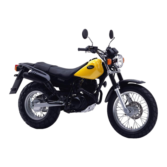
Page 11: Right View
DESCRIPTION Right view 13 12 11 10 8. Carrier (page 3-10) 11. Brake pedal (page 3-5, 6-21) 9. Battery (page 6-31) 12. Owner’s tool kit (page 6-1) 10. Engine oil level check window (page 6-9) 13. Fuse (page 6-34) -
Page 12: Controls And Instruments
DESCRIPTION Controls and instruments 1. Clutch lever (page 3-4, 6-19) 6. Indicator lights panel (page 3-1) 2. Left handlebar switches (page 3-2) 7. Right handlebar switches (page 3-3) 3. Speedometer unit (page 3-2) 8. Brake lever (page 3-4, 6-20) 4. Starter (choke) knob (page 3-8) 9. -
Page 13: Instrument And Control Functions
EAU00027 INSTRUMENT AND CONTROL FUNCTIONS EAU00063 High beam indicator light “&” This indicator light comes on when the high beam of the headlight is switched on. 1. Turn indicator light “5” 2. High beam indicator light “&” EAU00028 3. Neutral indicator light “N” Main switch EAU00056 The main switch controls the ignition... -
Page 14: Speedometer Unit
INSTRUMENT AND CONTROL FUNCTIONS NOTE: Only for the German model equipped with a speed limiter: The speed limiter prevents the motor- cycle from exceeding a riding speed of 80 km/h. 1. Speedometer 1. Lights switch 2. Odometer 2. Dimmer switch 3. - Page 15 INSTRUMENT AND CONTROL FUNCTIONS EAU00127 EAU00143 Turn signal switch Start switch “,” To signal a right-hand turn, push this Push this switch to crank the engine switch to “6”. To signal a left-hand with the starter. turn, push this switch to “4”. When released, the switch returns to the EC000005 center position.
-
Page 16: Clutch Lever
INSTRUMENT AND CONTROL FUNCTIONS 1. Clutch lever 1. Shift pedal 1. Brake lever N. Neutral EAU00152 EAU00158 EAU00157 Clutch lever Brake lever Shift pedal The clutch lever is located at the left The brake lever is located at the right The shift pedal is located on the left handlebar grip. -
Page 17: Brake Pedal
INSTRUMENT AND CONTROL FUNCTIONS To close the fuel tank cap 1. Insert the fuel tank cap into the tank opening with the key insert- ed in the lock, and then turn the cap clockwise. 2. Turn the key clockwise to the original position, then... -
Page 18: Fuel
INSTRUMENT AND CONTROL FUNCTIONS EAU00185 Immediately wipe off spilled fuel with a clean, dry, soft cloth, since fuel may deteriorate painted sur- faces or plastic parts. EAU00191 Recommended fuel: 1. Filler tube 2. Fuel level Regular unleaded gasoline EAU01183 with a research octane number Fuel of 91 or higher Make sure that there is sufficient fuel... -
Page 19: Fuel Cock
INSTRUMENT AND CONTROL FUNCTIONS OFF: Closed position ON: Normal position RES: Reserve position FUEL FUEL FUEL 1. Arrow mark positioned over “OFF” 1. Arrow mark positioned over “ON” 1. Arrow mark positioned over “RES” EAU03050 Fuel cock With the lever in this position, fuel This indicates reserve. -
Page 20: Starter (Choke) Knob "1
INSTRUMENT AND CONTROL FUNCTIONS To unlock the steering 1. Open the steering lock cover, and then insert the key. 2. Push the key in, turn it 1/8 turn counterclockwise that moves out, and then release it. 3. Remove the key, and then close the lock cover. -
Page 21: Seat
INSTRUMENT AND CONTROL FUNCTIONS 1. Bolt ( 1. Projection 1. Helmet holder 2. Seat holder EAU01092 EAU00260 To install the seat Seat Helmet holder 1. Insert the projection on the front To open the helmet holder, insert the of the seat into the seat holder To remove the seat key into the lock, and then turn the as shown. -
Page 22: Shock Absorber
8 Do not deform or damage the gas cylinder in any way, as this will result in poor damp- ing performance. 8 Always have a Yamaha dealer service the shock absorber. 3-10... -
Page 23: Sidestand
Therefore, check this system 8 It cuts the running engine when regularly as described below and the sidestand is moved down. have a Yamaha dealer repair it if it Periodically check the operation of does not function properly. the ignition circuit cut-off system according to the following procedure. - Page 24 5. Push the start switch. Does the engine start? The neutral switch may be defective. The motorcycle should not be ridden until checked by a Yamaha dealer. With the engine still running: 6. Move the sidestand up. 7. Keep the clutch lever pulled.
-
Page 25: Pre-Operation Checks
EAU01114 PRE-OPERATION CHECKS The condition of a vehicle is the owner’s responsibility. Vital components can start to deteriorate quickly and unexpect- edly, even if the vehicle remains unused (for example, as a result of exposure to the elements). Any damage, fluid leak- age or loss of tire air pressure could have serious consequences. - Page 26 PRE-OPERATION CHECKS ITEM CHECKS PAGE 9 Check fuel level. Fuel tank 3-5–3-6 9 Add fuel if necessary. Lights, signals and 9 Check proper operation. 3-2–3-3, 6-35–6-37 switches 9 Check fluid level. Battery 6-31–6-34 9 Add distilled water if necessary. NOTE: Pre-operation checks should be made each time the motorcycle is used.
-
Page 27: Operation And Important Riding Points
Yamaha dealer check the electrical ground and distract the opera- circuit. tor, resulting in a possible loss of control. -
Page 28: Starting A Warm Engine
OPERATION AND IMPORTANT RIDING POINTS EAU01258 6. After starting the engine, move Starting a warm engine the starter (choke) knob/lever Follow the same procedure as for back halfway. starting a cold engine with the excep- ECA00055 tion that the starter (choke) is not required when the engine is warm. -
Page 29: Shifting
OPERATION AND IMPORTANT RIDING POINTS EC000048 EAU02941 Recommended shift points (for Switzerland only) 8 Even with the transmission in The recommended shift points during the neutral position, do not acceleration are shown in the table coast for long periods of time below. -
Page 30: Tips For Reducing Fuel Consumption
(e.g., in traffic jams, at EC000049 traffic lights or at railroad cross- ings). If any engine trouble should occur during the engine break-in period, immediately have a Yamaha dealer check the vehicle. -
Page 31: Parking
OPERATION AND IMPORTANT RIDING POINTS FUEL 1. Arrow mark positioned over “OFF” EAU00457 Parking When parking, stop the engine, remove the key from the main switch, and then turn the fuel cock lever to “OFF”. EW000058 8 Since the engine and exhaust system can become very hot, park in a place where pedestri- ans or children are not likely... -
Page 32: Periodic Maintenance And Minor Repair
If you do not have the tools or experi- Periodic inspection, adjustment and ence required for a particular job, lubrication will keep your vehicle in have a Yamaha dealer perform it for the safest and most efficient condi- you. tion possible. The most important... -
Page 33: Periodic Maintenance And Lubrication Chart
8 The annual checks must be performed every year, except if kilometer-based maintenance is performed instead. 8 From 30,000 km, repeat the maintenance intervals starting from 6,000 km. 8 Items marked with an asterisk should be performed by a Yamaha dealer as they require special tools, data and technical skills. - Page 34 PERIODIC MAINTENANCE AND MINOR REPAIR ODOMETER READING ( 1,000 km) ANNUAL ITEM CHECK OR MAINTENANCE JOB CHECK • Check runout, spoke tightness and for damage. Wheels • Tighten spokes if necessary. • Check tread depth and for damage. • Replace if necessary. Tires •...
- Page 35 PERIODIC MAINTENANCE AND MINOR REPAIR ODOMETER READING ( 1,000 km) ANNUAL ITEM CHECK OR MAINTENANCE JOB CHECK Engine oil • Change. Engine oil filter element • Replace. Engine oil strainer • Clean. Front and rear brake • Check operation. switches Moving parts and cables •...
-
Page 36: Removing And Installing Cowling And Panels
PERIODIC MAINTENANCE AND MINOR REPAIR 1. Cowling A 1. Panel B 1. Cowling A 2. Panel A 2. Screw EAU03516 EAU01145 Removing and installing the Cowling A cowling and panels To remove the cowling The cowling and panels shown above Remove the screw, and then pull the cowling off as shown. - Page 37 PERIODIC MAINTENANCE AND MINOR REPAIR 1. Panel A 1. Panel B 2. Screw ( 2) EAU00494 To install the panel EAU01492 Panel B Place the panel in the original posi- Panel A To remove the panel tion, and then install the screws. To remove the panel Pull the panel off as shown.
-
Page 38: Checking The Spark Plug
PERIODIC MAINTENANCE AND MINOR REPAIR EAU01833 Checking the spark plug The spark plug is an important engine component, which is easy to check. Since heat and deposits will cause any spark plug to slowly erode, the spark plug should be removed and checked in accordance with the periodic maintenance and lubrication chart. - Page 39 Instead, 1. Measure the spark plug gap with soon as possible. have a Yamaha dealer check the a wire thickness gauge and, if motorcycle. necessary, adjust the gap to 4. Install the spark plug cap. specification. 2. Check the spark plug for elec-...
-
Page 40: Engine Oil And Oil Filter Element
PERIODIC MAINTENANCE AND MINOR REPAIR EAU03564 Engine oil and oil filter element The engine oil level should be checked before each ride. In addition, the oil must be changed and the oil filter element cleaned at the intervals specified in the periodic maintenance and lubrication chart. - Page 41 PERIODIC MAINTENANCE AND MINOR REPAIR 1. Engine oil drain bolt 1. Strainer 1. Oil filter element cover 2. Compression spring 2. Screw ( 2) 3. O-ring 3. Oil filter element drain bolt 4. Remove the oil filter element EC000070 drain bolt to drain the oil from the When removing the engine oil oil filter element.
- Page 42 PERIODIC MAINTENANCE AND MINOR REPAIR 9. Install the oil filter element cover Tightening torque: by installing the screws and the Engine oil drain bolt: drain bolt. Then tightening them 43 Nm (4.3 m·kg) to the specified torque. 12. Add the specified amount of the Tightening torques: recommended engine oil, and Oil filter element cover screw:...
-
Page 43: Cleaning The Air Filter Element And Check Hose
PERIODIC MAINTENANCE AND MINOR REPAIR EC000072 EAU03562 Cleaning the air filter element and check hose 8 In order to prevent clutch slip- The air filter element should be page (since the engine oil also cleaned at the intervals specified in lubricates the clutch), do not the periodic maintenance and lubrica- mix any chemical additives... - Page 44 PERIODIC MAINTENANCE AND MINOR REPAIR EC000082 8 Make sure that the air filter ele- ment is properly seated in the air filter case. 8 The engine should never be operated without the air filter element installed, otherwise the piston(s) and/or cylinder(s) 1.
-
Page 45: Adjusting The Carburetor
The engine idling speed must be cated adjustment. Therefore, most checked and, if necessary, adjusted carburetor adjustments should be left as follows at the intervals specified in to a Yamaha dealer, who has the the periodic maintenance and lubrica- necessary professional knowledge tion chart. experience. -
Page 46: Adjusting The Throttle Cable Free Play
3. Tighten the locknut. Engine idling speed: 1,300–1,500 r/min NOTE: If the specified idling speed cannot be obtained as described above, have a Yamaha dealer make the adjustment. 6-15... -
Page 47: Adjusting The Valve Clearance
1.75 kg/cm this from occurring, the valve clear- Maximum * 1.50 bar 1.75 bar ance must be adjusted by a Yamaha Tire air pressure 125 kPa 125 kPa dealer at the intervals specified in the The tire air pressure should be Off-road riding 1.25 kg/cm... - Page 48 PERIODIC MAINTENANCE AND MINOR REPAIR EWA00040 EW000079 Because loading has an enormous 8 Have a Yamaha dealer replace impact on the handling, braking, excessively worn tires. performance and safety character- Besides being illegal, operat- istics of your motorcycle, you ing the motorcycle with exces-...
-
Page 49: Spoke Wheels
PERIODIC MAINTENANCE AND MINOR REPAIR Tire information EAU00681 EAU00685 Spoke wheels This motorcycle is equipped with tube To maximize the performance, dura- 8 Have a Yamaha dealer replace tires. bility, and safe operation of your excessively worn tires. EW000078 motorcycle, note the following points Besides being illegal, operat- regarding the specified wheels. -
Page 50: Adjusting The Clutch Lever Free Play
PERIODIC MAINTENANCE AND MINOR REPAIR 8 Ride at moderate speeds after 3. If the specified clutch lever free changing a tire since the tire sur- play could obtained face must first be “broken in” for described above, tighten the it to develop its optimal charac- locknut and skip the rest of the teristics. -
Page 51: Adjusting The Brake Lever Free Play
2. Adjusting bolt 2. Adjusting bolt in the hydraulic system, have c. Free play 5. Loosen the locknuts at the a Yamaha dealer bleed the EAU00696 crankcase. Adjusting the brake lever system before operating the 6. To increase the clutch lever free free play motorcycle. -
Page 52: Adjusting The Brake Pedal Position And Free Play
Periodically check the brake pedal EW000104 free play and, if necessary, adjust it as follows. It is advisable to have a Yamaha dealer make these adjustments. Brake pedal position The top of the brake pedal should be positioned... -
Page 53: Adjusting The Rear Brake Light Switch
8 If proper adjustment cannot be obtained as described, have a 1. Brake pedal free play adjusting nut 1. Brake light switch Yamaha dealer make this 2. Adjusting nut adjustment. To increase the brake pedal free... -
Page 54: Checking The Front Brake Pads And Rear Brake Shoes
Yamaha dealer wear indicator reaches the wear limit replace the brake pads as a set. line, have a Yamaha dealer replace the brake shoes as a set. 6-23... -
Page 55: Checking The Brake Fluid Level
However, if ber seals may deteriorate, caus- the brake fluid level goes down ing leakage and poor braking suddenly, have a Yamaha dealer 1. Minimum level mark performance. check the cause. EAU03196... -
Page 56: Changing The Brake Fluid
PERIODIC MAINTENANCE AND MINOR REPAIR EAU03238 EAU00744 Changing the brake fluid Drive chain slack Have a Yamaha dealer change the The drive chain slack should be brake fluid at the intervals specified in checked before each ride and adjust- the periodic maintenance and lubrica- ed if necessary. -
Page 57: Lubricating The Drive Chain
After adjusting the brake pedal For a thorough cleaning, have a Make sure that both adjusting plates free play, check the operation of Yamaha dealer remove the drive are in the same position for proper the brake light. chain and soak it in solvent. -
Page 58: Checking And Lubricating The Cables
If a cable is damaged or does not move smoothly, have a Yamaha dealer check or replace it. Recommended lubricant: Engine oil 6-27... -
Page 59: Checking And Lubricating The Throttle Grip And Cable
PERIODIC MAINTENANCE AND MINOR REPAIR EAU03209 4. Grease the metal-to-metal con- Checking and lubricating the tact surface of the throttle grip, throttle grip and cable and then install the grip by The operation of the throttle grip and installing the screws. the condition of the throttle cable should be checked before each ride, Recommended lubricant:... -
Page 60: Checking And Lubricating The Brake And Clutch Levers
Recommended lubricant: Recommended lubricant: EW000113 Lithium-soap-based grease Lithium-soap-based grease If the sidestand does not move up (all-purpose grease) (all-purpose grease) down smoothly, have Yamaha dealer check or repair it. Recommended lubricant: Lithium-soap-based grease (all-purpose grease) 6-29... -
Page 61: Checking The Front Fork
EC000098 If any damage is found or the front fork does not operate smoothly, have a Yamaha dealer check or repair it. 6-30... -
Page 62: Checking The Wheel Bearings
Yamaha intervals specified in the periodic dealer check the wheel bearings. maintenance and lubrication chart. - Page 63 PERIODIC MAINTENANCE AND MINOR REPAIR EW000116 8 Electrolyte is poisonous and dangerous since it contains sulfuric acid, which causes severe burns. Avoid any con- tact with skin, eyes or clothing and always shield your eyes when working near batteries. In case of contact, administer 1.
- Page 64 PERIODIC MAINTENANCE AND MINOR REPAIR To store the battery 1. If the motorcycle will not be used more than month, remove the battery, fully charge it, and then place it in a cool, dry place. 2. If the battery will be stored for more than two months, check the specific gravity of the electrolyte 1.
-
Page 65: Replacing The Fuse
2. Spare fuse the devices operate. EAU01307 Replacing the fuse 4. If the fuse immediately blows again, have a Yamaha dealer The fuse holder is located behind check the electrical system. panel B. (See page 6-6 for panel removal and installation procedures.) If the fuse is blown, replace it as fol- lows. -
Page 66: Replacing The Headlight Bulb
PERIODIC MAINTENANCE AND MINOR REPAIR 1. Bolt ( 2) 1. Coupler 1. Headlight bulb holder 2. Headlight bulb cover EAU01158 4. Remove the headlight bulb hold- 3. Disconnect the headlight cou- Replacing the headlight bulb er by turning it counterclockwise, pler, and then remove the head- If the headlight bulb burns out, and then remove the defective... -
Page 67: Replacing A Turn Signal Light Bulb
1. Remove the turn signal light lens 8. Install the cowling. by removing the screw. 9. Have a Yamaha dealer adjust 2. Remove the defective bulb by the headlight beam if necessary. pushing it in and turning it coun- terclockwise. -
Page 68: Replacing The Tail/Brake Light Bulb
PERIODIC MAINTENANCE AND MINOR REPAIR EAU01579 Supporting the motorcycle Since this model is not equipped with a centerstand, follow these precau- tions when removing the front and rear wheel or performing other main- tenance requiring the motorcycle to stand upright. Check that the motor- cycle is in a stable and level position before starting any maintenance. -
Page 69: Front Wheel
To remove the front wheel EW000122 8 It is advisable to have a Yamaha dealer service the wheel. 8 Securely support the motorcy- cle so that there is no danger of it falling over. -
Page 70: Rear Wheel
To remove the rear wheel 2. Lift the wheel up between the EW000122 fork legs. 8 It is advisable to have a NOTE: Yamaha dealer service the Make sure that there is enough wheel. space between brake pads... - Page 71 PERIODIC MAINTENANCE AND MINOR REPAIR 2. Remove the brake pedal free 3. Install the axle nut, and then play adjusting nut, and then dis- lower the rear wheel so that it is connect the brake rod from the on the ground. brake camshaft lever.
-
Page 72: Troubleshooting
Use only genuine Yamaha replace- ment parts. Imitation parts may look like Yamaha parts, but they are often inferior, have a shorter service life and can lead to expensive repair bills. 6-41... -
Page 73: Troubleshooting Chart
2. Compression There is compression. Go to ignition check. Use the electric starter. No compression. Ask a Yamaha dealer to inspect. 3. Ignition Wipe clean with dry cloth and Open throttle half-way and start Wet. Remove spark correct spark gap or replace plug. -
Page 74: Motorcycle Care And Storage
EAU03521 MOTORCYCLE CARE AND STORAGE Care Before cleaning Cleaning 1. Cover the muffler outlet with a ECA00010 While the open design of a motorcy- plastic bag after the engine has cle reveals the attractiveness of the 8 Avoid using strong acidic cooled down. - Page 75 MOTORCYCLE CARE AND STORAGE 8 Do not use any harsh chemical 8 For motorcycles equipped After riding in the rain, near the sea products on plastic parts. Be with a windshield: Do not use or on salt-sprayed roads sure to avoid using cloths or strong cleaners hard...
- Page 76 4. To prevent corrosion, it is recom- NOTE: cle test its braking perfor- mended to apply a corrosion pro- Consult a Yamaha dealer for advice mance and cornering behav- on what products to use. tection spray on all metal, includ- ior.
-
Page 77: Storage
MOTORCYCLE CARE AND STORAGE Storage Long-term c. Install the spark plug cap onto Before storing your motorcycle for Short-term the spark plug, and then place several months: Always store your motorcycle in a the spark plug on the cylinder 1. Follow all the instructions in the cool, dry place and, if necessary, pro- head so that the electrodes are “Care”... - Page 78 MOTORCYCLE CARE AND STORAGE 6. Lubricate all control cables and NOTE: the pivoting points of all levers Make any necessary repairs before and pedals as well as of the storing the motorcycle. sidestand/centerstand. 7. Check and, if necessary, correct the tire air pressure, and then lift the motorcycle so that both of its wheels ground.
-
Page 79: Specifications
EAU01038 SPECIFICATIONS Specifications Model TW125 Engine oil –20° –10° 0° 10° 20° 30° 40° 50°C Dimensions Type Overall length 2,140 mm SAE 10W/30 Overall width 810 mm SAE 10W/40 Overall height 1,120 mm SAE 15W/40 Seat height 805 mm SAE 20W/40... - Page 80 SPECIFICATIONS Fuel Gear ratio 2.250 Type Regular unleaded gasoline 1.476 Fuel tank capacity 7.0 L 1.125 Reserve amount 1.0 L 0.926 Carburetor 0.793 Manufacturer TEIKEI Chassis Frame type Diamond Model quantity Y24P Caster angle 26° Spark plug Trail 95 mm Manufacturer/Type NGK/DR8EA Tires...
- Page 81 SPECIFICATIONS Maximum load* 180 kg Rear Air pressure (cold tire) Type Drum brake up to 80 kg load* Operation Right foot operation Front 150 kPa (1.50 kg/cm , 1.50 bar) Suspension Rear 150 kPa (1.50 kg/cm , 1.50 bar) Front 80 kg load–Maximum Type Telescopic fork...
- Page 82 SPECIFICATIONS Headlight bulb type Incandescence Bulb voltage, wattage quantity Headlight 12 V, 45/40 W Tail/brake light 12 V, 5/21 W Front turn signal light 12 V, 21 W Rear turn signal light 12 V, 21 W Marker light 12 V, 4 W Meter lighting 12 V, 3.4 W Neutral indicator light...
-
Page 83: Conversion Table
SPECIFICATIONS EAU01064 Conversion table CONVERSION TABLE All specification data in this manual are listed in SI and METRIC TO IMPERIAL METRIC UNITS. Metric unit Multiplier Imperial unit Use this table to convert METRIC unit data to m • kg 7.233 ft •... -
Page 84: Consumer Information
Record the key identification number, vehicle identification number and model label information in the spaces provided below for assistance when ordering spare parts from a Yamaha dealer or for reference in case the vehicle is stolen. 1. KEY IDENTIFICATION 1. Key identification number 1. -
Page 85: Model Label
1. Model label EAU01049 Model label The model label is affixed to the loca- tion shown in the figure. Record the information on this label in the space provided. This information will be needed when ordering spare parts from a Yamaha dealer. - Page 87 YAMAHA MOTOR CO., LTD. PRINTED IN JAPAN PRINTED ON RECYCLED PAPER 2000·5–0.1 1(E)
- Page 88 YAMAHA MOTOR CO., LTD. PRINTED ON RECYCLED PAPER PRINTED IN JAPAN 2000·5–0.1 1(E)