Dell DIMENSION E310 DCSM Owner's Manual
Hide thumbs
Also See for DIMENSION E310 DCSM:
- Owner's manual (140 pages) ,
- Installation instructions (1 page)
Table of Contents
Advertisement
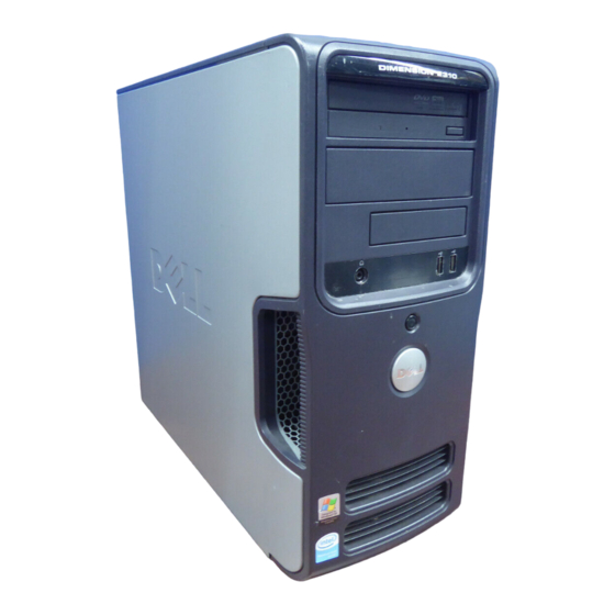
Dell™ Dimension™ 3100/E310
CD or DVD activity light
FlexBay for optional
floppy drive or Media
Card Reader
headphone connector
diagnostic lights
cover latch release
card slots for
PCI (2),
PCI Express x1 (1)
Model DCSM
w w w . d e l l . c o m | s u p p o r t . d e l l . c o m
Owner's Manual
Service Tag
CD or DVD eject button
USB 2.0 connectors (2)
1
2
3
4
hard drive activity light
power button
power connector
sound-card connectors
USB 2.0 connectors (4)
network adapter
VGA video connector (integrated)
Advertisement
Table of Contents
Troubleshooting

Related Manuals for Dell DIMENSION E310 DCSM


Summary of Contents for Dell DIMENSION E310 DCSM
- Page 1 Dell™ Dimension™ 3100/E310 Owner’s Manual Service Tag CD or DVD eject button CD or DVD activity light FlexBay for optional floppy drive or Media USB 2.0 connectors (2) Card Reader headphone connector hard drive activity light diagnostic lights power button...
- Page 2 Trademarks used in this text: Dell, the DELL logo, Inspiron, Dell Precision, Dimension, OptiPlex, Latitude, PowerEdge, PowerVault, PowerApp, DellNet, and PowerConnect are trademarks of Dell Inc.; Intel and Pentium are registered trademarks of Intel Corporation; Microsoft, Windows, and Outlook are registered trademarks of Microsoft Corporation.
-
Page 3: Table Of Contents
Contents ....... . Finding Information Setting Up and Using Your Computer Setting Up a Printer . - Page 4 Configuring Your Computer for RAID Using the Intel Matrix ......Storage Manager .
- Page 5 XP System Restore ... . . Using Dell™ PC Restore by Symantec ....
- Page 6 Drive Panels ........Removing the Drive Panel .
- Page 7 CDs and DVDs ....Dell Technical Support Policy (U.S. Only) Definition of "Dell-Installed" Software and Peripherals ..
- Page 8 Contents...
-
Page 9: Finding Information
NOTE: Additional information may ship with your computer. What Are You Looking For? Find It Here • Warranty information Dell™ Product Information Guide • Terms and Conditions (U.S. only) • Safety instructions • Regulatory information • Ergonomics information • End User License Agreement •... - Page 10 • Community — Online discussion with other Dell Corporate, government, and education customers customers can also use the customized Dell Premier Support website at • Upgrades — Upgrade information for components, such premier.support. dell.com. as memory, the hard drive, and the operating system •...
- Page 11 What Are You Looking For? Find It Here • How to use Windows XP Windows Help and Support Center • How to work with programs and files Click the Start button and click Help and Support. • How to personalize my desktop Type a word or phrase that describes your problem and click the arrow icon.
- Page 12 Finding Information...
-
Page 13: Setting Up And Using Your Computer
Setting Up and Using Your Computer Setting Up a Printer NOTICE: Complete the operating system setup before you connect a printer to the computer. See the documentation that came with the printer for setup information, including how to: • Obtain and install updated drivers •... -
Page 14: Connecting To The Internet
USB connector on computer USB printer cable USB connector on printer Connecting to the Internet NOTE: ISPs and ISP offerings vary by country. To connect to the Internet, you need a modem or network connection and an Internet service provider (ISP), such as AOL or MSN. Your ISP will offer one or more of the following Internet connection options: •... -
Page 15: Setting Up Your Internet Connection
Setting Up Your Internet Connection To set up an AOL or MSN connection: 1 Save and close any open files, and exit any open programs. ® ® 2 Double-click the MSN Explorer or AOL icon on the Microsoft Windows desktop. 3 Follow the instructions on the screen to complete the setup. -
Page 16: Playing Cds And Dvds
Playing CDs and DVDs NOTICE: Do not press down on the CD or DVD tray when you open or close it. Keep the tray closed when you are not using the drive. NOTICE: Do not move the computer when you are playing CDs or DVDs. 1 Press the eject button on the front of the drive. -
Page 17: Adjusting The Volume
Eject Go to the next track A DVD player includes the following basic buttons: Stop Restart the current chapter Play Fast forward Pause Fast reverse Advance a single frame while in pause mode Go to the next title or chapter Continuously play the current title or chapter Go to the previous title or chapter Eject... -
Page 18: Adjusting The Picture
DVD/CD-RW combo drive. NOTE: The types of CD or DVD drives offered by Dell may vary by country. The following instructions show how to make an exact copy of a CD or DVD. You can also use Sonic RecordNow for other purposes, including creating CDs from audio files on your computer and creating MP3 CDs. -
Page 19: Using Blank Cd-Rs And Cd-Rws
4 To copy the CD or DVD: • If you have one CD or DVD drive, ensure that the settings are correct and click Copy. The computer reads your source CD or DVD and copies it to a temporary folder on your computer hard drive. -
Page 20: Using A Media Card Reader (Optional)
Using a Media Card Reader (Optional) Use the Media Card Reader to transfer data directly to your computer. The Media Card Reader supports the following memory types: • xD-Picture Card • SmartMedia (SMC) • CompactFlash Type I and II (CF I/II) •... -
Page 21: Setting Up A Home And Office Network
To use the Media Card Reader: 1 Check the media or card to determine the proper orientation for insertion. 2 Slide the media or card into the appropriate slot until it is completely seated in the connector. If you encounter resistance, do not force the media or card. Check the card orientation and try again. -
Page 22: Power Management
3 Click Checklist for creating a network. NOTE: Selecting the connection method This computer connects directly to the Internet enables the integrated firewall provided with Windows XP. 4 Complete the checklist and required preparations. 5 Return to the Network Setup Wizard and follow the instructions on the screen. Power Management ®... -
Page 23: Power Options Properties
Because hibernate mode requires a special file on your hard drive with enough disk space to store the contents of the computer memory, Dell creates an appropriately sized hibernate mode file before shipping the computer to you. If the computer’s hard drive becomes corrupted, Windows XP recreates the hibernate file automatically. -
Page 24: About Raid Configurations
Of the several RAID configurations available in the computer industry for different types of uses, Dell offers RAID level 1 on your computer. This configuration is recommended for users that desire a higher level of data integrity. -
Page 25: Using Raid With Hard Drive Passwords
Using RAID with Hard Drive Passwords If you are using a hard-drive security option available in system setup (see page 104), you should not use a RAID configuration. Using a RAID configuration requires that the hard drive password be cleared to allow data access. RAID Level 1 RAID level 1 uses a data-redundancy storage technique known as "mirroring."... -
Page 26: Setting Your Computer To Raid-Enabled Mode
and the Intel Matrix Storage Console. Both methods require that you set your computer to RAID-enabled mode before starting any of the RAID configuration procedures in this document. Setting Your Computer to RAID-Enabled Mode 1 Enter system setup (see page 103). 2 Press the up- and down-arrow keys to highlight Drives, and press <Enter>. -
Page 27: Configuring Your Computer For Raid Using The Intel Matrix Storage Manager
Deleting a RAID Volume NOTE: When you perform this operation, all data on the RAID drives will be lost. NOTE: If your computer currently boots to RAID and you delete the RAID volume in the Intel RAID Option ROM utility, your computer will become unbootable. 1 Press <Ctrl><i>... - Page 28 8 Click Finish to create the volume, or click Back to make changes. 9 Follow Microsoft Windows procedures for creating a partition on the new RAID volume. Deleting a RAID Volume NOTE: While this procedure deletes the RAID 1 volume, it also splits the RAID 1 volume into two non- RAID hard drives with a partition, and leaves any existing data files intact.
-
Page 29: Hyper-Threading
You can enable or disable Hyper-Threading through system setup. For more information on accessing system setup, see page 103. For more information on Hyper-Threading, search the Knowledge Base on the Dell Support website at support.dell.com. Setting Up and Using Your Computer... - Page 30 Setting Up and Using Your Computer...
-
Page 31: Solving Problems
— If you have to repeatedly reset time and date information after turning on the computer, or if an incorrect time or date displays during start-up, replace the battery (see page 95). If the battery still does not work properly, contact Dell (see page 114). Drive Problems... -
Page 32: Cd And Dvd Drive Problems
E S T T H E D R I V E — • Insert another floppy disk, CD, or DVD to eliminate the possibility that the original one is defective. • Insert a bootable floppy disk and restart the computer. L E A N T H E D R I V E O R D I S K —... -
Page 33: Hard Drive Problems
Hard drive problems H E C K I S K — Click the Start button and click My Computer. Right-click Local Disk C:. Click Properties. Click the Tools tab. Under Error-checking, click Check Now. Click Scan for and attempt recovery of bad sectors. Click Start. -
Page 34: Error Messages
E R I F Y T H A T T H E M O D E M I S C O M M U N I C A T I N G W I T H I N D O W S —... -
Page 35: Media Card Reader Problems
If so, run the program that you want to use first. P E R A T I N G S YS T E M N O T F O U N D — Contact Dell (see page 114). Media Card Reader Problems O D R I V E L E T T E R I S A S S I G N E D —... -
Page 36: Keyboard Problems
Keyboard Problems CAUTION: Before you begin any of the procedures in this section, follow the safety instructions located in the Product Information Guide. H E C K T H E K E Y B O A R D C A B L E —... -
Page 37: A Program Stops Responding
A program stops responding N D T H E P R O G R A M — Press <Ctrl><Shift><Esc> simultaneously. Click Applications. Click the program that is no longer responding. Click End Task. A program crashes repeatedly NOTE: Software usually includes installation instructions in its documentation or on a floppy disk or CD. H E C K T H E S O F T W A R E D O C U M E N T A T I O N —... -
Page 38: Other Software Problems
• See the software documentation for minimum memory requirements. If necessary, install additional memory (see page 67). • Reseat the memory modules (see page 67) to ensure that your computer is successfully communicating with the memory. • Run the Dell Diagnostics (see page 50). Solving Problems... -
Page 39: Mouse Problems
• Ensure that you are following the memory installation guidelines (see page 67). • Your computer supports DDR2 memory. For more information about the type of memory supported by your computer, see "Memory" on page 65. • Run the Dell Diagnostics (see page 50). Mouse Problems CAUTION: Before you begin any of the procedures in this section, follow the safety instructions located in the Product Information Guide. -
Page 40: Network Problems
Network Problems CAUTION: Before you begin any of the procedures in this section, follow the safety instructions located in the Product Information Guide. H E C K T H E N E T W O R K C A B L E C O N N E C T O R —... -
Page 41: Printer Problems
F T H E P O W E R L I G H T I S O F F — The computer is either turned off or is not receiving power. • Reseat the power cable into both the power connector on the back of the computer and the electrical outlet. -
Page 42: Scanner Problems
H E C K T H E P R I N T E R C A B L E C O N N E C T I O N S — • See the printer documentation for cable connection information. •... -
Page 43: Sound And Speaker Problems
E R I F Y T H A T T H E S C A N N E R I S R E C O G N I Z E D B Y I C R O S O F T I N D O W S —... -
Page 44: No Sound From Headphones
E I N S T A L L T H E S O U N D D R I V E R — See "Reinstalling Drivers" on page 52. U N T H E A R D W A R E R O U B L E S H O O T E R —... -
Page 45: If The Screen Is Difficult To Read
If the screen is difficult to read H E C K T H E M O N I T O R S E T T I N G S — See the monitor documentation for instructions on adjusting the contrast and brightness, demagnetizing (degaussing) the monitor, and running the monitor self-test. O V E T H E S U B W O O F E R A W A Y F R O M T H E M O N I T O R —... - Page 46 Solving Problems...
-
Page 47: Advanced Troubleshooting
• If available, install properly working memory of the same type into your computer (see page 67). • If the problem persists, contact Dell (see page 114). A possible graphics failure has occurred. If the problem persists, contact Dell (see page 114). - Page 48 • If available, install properly working memory of the same type into your computer (see page 67). • If the problem persists, contact Dell (see page 114). Memory modules are detected, but a memory • Ensure that no special memory configuration or compatibility error exists.
- Page 49 (see page 103) to make sure the boot sequence is correct for the devices installed on your computer. • If the problem persists, contact Dell (see page 114). The computer is in a normal operating None.
-
Page 50: Dell Diagnostics
If you cannot resolve the error condition, contact Dell (see page 114 NOTE: The Service Tag for your computer is located at the top of each test screen. If you contact Dell, technical support will ask for your Service Tag. Advanced Troubleshooting... -
Page 51: Drivers
Parameters Allows you to customize the test by changing the test settings. 4 Close the test screen to return to the Main Menu screen. To exit the Dell Diagnostics and restart the computer, close the Main Menu screen. Drivers What Is a Driver? A driver is a program that controls a device such as a printer, mouse, or keyboard. -
Page 52: Identifying Drivers
Reinstalling Drivers NOTICE: The Dell Support website at support.dell.com provides approved drivers for Dell™ computers. If you install drivers obtained from other sources, your computer might not work correctly. Using Windows XP Device Driver Rollback If a problem occurs on your computer after you install or update a driver, use Windows XP Device Driver Rollback to replace the driver with the previously installed version. -
Page 53: Resolving Software And Hardware Incompatibilities
• Dell PC Restore by Symantec restores your hard drive to the operating state it was in when you purchased the computer. Dell PC Restore permanently deletes all data on the hard drive and removes any applications installed after you received the computer. -
Page 54: Using Microsoft ® Windows ® Xp System Restore
NOTE: The procedures in this document were written for the Windows default view, so they may not work if you set your Dell™ computer to the Windows Classic view. Creating a Restore Point 1 Click the Start button and click Help and Support. -
Page 55: Using Dell™ Pc Restore By Symantec
Dell PC Restore is not available in all countries. Use Dell PC Restore by Symantec only as the last method to restore your operating system. PC Restore restores your hard drive to the operating state it was in when you purchased the computer. - Page 56 5 When prompted, click Finish to reboot the computer. NOTE: Do not manually shut down the computer. Click Finish and let the computer completely reboot. 6 When prompted, click Yes. The computer restarts. Because the computer is restored to its original operating state, the screens that appear, such as the End User License Agreement, are the same ones that appeared the first time the computer was turned on.
-
Page 57: Removing And Installing Parts
You have performed the steps in "Turning Off Your Computer" (see page 57) and "Before Working Inside Your Computer" (see page 58). • You have read the safety information in your Dell™ Product Information Guide. NOTE: Unless otherwise noted, a component can be replaced or—if purchased separately—installed by performing the removal procedure in reverse order. -
Page 58: Before Working Inside Your Computer
NOTICE: Only a certified service technician should perform repairs on your computer. Damage due to servicing that is not authorized by Dell is not covered by your warranty. NOTICE: When you disconnect a cable, pull on its connector or on its strain-relief loop, not on the cable itself. -
Page 59: Front View Of The Computer
Front View of the Computer Removing and Installing Parts... - Page 60 Use the lights to help you troubleshoot a computer problem based on the diagnostic code. For more information, see "Diagnostic Lights" on page 47. Service Tag Use to identify your computer when you access the Dell Support website or call technical support. Removing and Installing Parts...
-
Page 61: Back View Of The Computer
Back View of the Computer Removing and Installing Parts... - Page 62 power connector Insert the power cable. sound card connectors (3) • Line-in connector — Use the blue line-in connector to attach a record/playback device such as a cassette player, CD player, or VCR. • Line-out connector — Use the green line-out connector to attach headphones and most speakers with integrated amplifiers.
-
Page 63: Removing The Computer Cover
Removing the Computer Cover CAUTION: Before you begin any of the procedures in this section, follow the safety instructions located in the Product Information Guide. CAUTION: To guard against electrical shock, always unplug your computer from the electrical outlet before removing the cover. 1 Follow the procedures in "Before You Begin"... -
Page 64: Inside View Of Your Computer
4 Locate the three hinge tabs on the bottom edge of the computer. 5 Grip the sides of the computer cover and pivot the cover up, using the bottom hinges as leverage points. 6 Release the cover from the hinge tabs and set it aside in a secure location. Inside View of Your Computer CAUTION: Before you begin any of the procedures in this section, follow the safety instructions... -
Page 65: System Board Components
System Board Components memory module SATA connectors front panel I/O connectors (1, 2) (SATA-0 and SATA-1) connector processor main power power connector connector IDE drive connector processor and heat sink connector FlexBay USB connector floppy drive connector (FLOPPY) PCI Express x1 fan connector card connector (CPU FAN) -
Page 66: Ddr2 Memory Overview
Be sure to install a single memory module in DIMM connector 1, the connector closest to the processor, before you install a module in the other connector. matched pair of memory modules in DIMM connectors 1 and 2 NOTE: Memory purchased from Dell is covered under your computer warranty. Removing and Installing Parts... -
Page 67: Installing Memory
Dell. If possible, do not pair an original memory module with a new memory module. Otherwise, your computer may not start properly. -
Page 68: Removing Memory
NOTICE: To avoid damage to the memory module, press the module straight down into the connector while you apply equal force to each end of the module. 4 Insert the module into the connector until the module snaps into position. If you insert the module correctly, the securing clips snap into the cutouts at each end of the module. -
Page 69: Cards
You can do so by touching an unpainted metal surface on the computer chassis. Your Dell™ computer provides the following slots for PCI and PCI Express cards: •... - Page 70 Installing an Expansion Card 1 Follow the procedures in "Before You Begin" on page 57. release tab card retention door alignment bar alignment guide filler bracket 2 Gently push the release tab on the inside of the card retention door to pivot the door open. Because the door is captive, it will remain in the open position.
- Page 71 not fully seated card bracket within slot fully seated card alignment guide bracket caught outside of slot alignment bar 7 Before you close the card retention door, ensure that: • The tops of all cards and filler brackets are flush with the alignment bar. •...
- Page 72 3 If you are removing the card permanently, install a filler bracket in the empty card-slot opening. If you need a filler bracket, contact Dell (see page 114). NOTE: Installing filler brackets over empty card-slot openings is necessary to maintain FCC certification of the computer.
-
Page 73: Drive Panels
NOTICE: To connect a network cable, first plug the cable into the network port or device, and then plug it into the computer. 5 Replace the computer cover, reconnect the computer and devices to electrical outlets, and then turn them on. 6 Remove the card’s driver from the operating system. -
Page 74: Removing The Drive Panel
Removing the Drive Panel 1 Follow the procedures in "Before You Begin" on page 57. sliding plate lever sliding plate drive panel 2 Grasp the sliding plate lever and push it towards the base of the computer until the drive panel snaps open. -
Page 75: Removing The Drive-Panel Insert
Removing the Drive-Panel Insert drive-panel insert latch drive panel drive-panel insert 1 Remove the drive panel. 2 Press the drive-panel insert latch inwards to unlatch it from the drive panel. 3 Pivot the drive-panel insert out and away from the drive panel. 4 Set the drive-panel insert aside in a secure location. -
Page 76: Replacing The Drive Panel
Replacing the Drive Panel 1 Follow the procedures in "Before You Begin" on page 57. sliding plate lever sliding plate drive panel 2 Align the drive panel tabs with the side-door hinges. 3 Rotate the drive panel toward the computer until it snaps into place on the front panel. 4 Grasp the sliding plate lever and pull it towards the top of the computer, snapping it into the closed position to secure the drive panel. -
Page 77: Ide Drive Addressing
CD/DVD drive(s) FlexBay for optional floppy drive or Media Card Reader hard drive bay for second hard drive (optional) Connect CD/DVD drives to the connector labeled "IDE" on the system board. Serial ATA hard drives should be connected to the connectors labeled "SATA0" or "SATA1" on the system board. IDE Drive Addressing When you connect two IDE devices to a single IDE interface cable and configure them for the cable select setting, the device attached to the last connector on the interface cable is the master or... -
Page 78: Drive Interface Connectors
Drive Interface Connectors Most interface connectors are keyed for correct insertion; that is, a notch or a missing pin on one connector matches a tab or a filled-in hole on the other connector. Keyed connectors ensure that the pin-1 wire in the cable (indicated by the colored stripe along one edge of the IDE cable—serial ATA cables do not use a colored stripe) goes to the pin-1 end of the connector. -
Page 79: Connecting And Disconnecting Drive Cables
Connecting and Disconnecting Drive Cables When removing an IDE drive data cable, grasp the colored pull tab and pull until the connector detaches. When connecting and disconnecting a serial ATA data cable, hold the cable by the black connector at each end. Like IDE connectors, the serial ATA interface connectors are keyed for correct insertion;... -
Page 80: Removing A Hard Drive
Removing a Hard Drive 1 Follow the procedures in "Before You Begin" on page 57. 2 Disconnect the power and hard-drive cables from the drive. serial ATA data cable power cable 3 Press in the blue tabs on each side of the drive towards each other and slide the drive up and out of the computer. -
Page 81: Installing A Hard Drive
Installing a Hard Drive 1 Unpack the replacement hard drive, and prepare it for installation. 2 Check the documentation for the drive to verify that it is configured for your computer. NOTE: If your replacement hard drive does not have the plastic guide bracket attached, remove the bracket from the old drive by unsnapping it from the drive. -
Page 82: Adding A Second Hard Drive (Optional)
NOTICE: To connect a network cable, first plug the cable into the network port or device, and then plug it into the computer. 7 Connect your computer and devices to electrical outlets, and turn them on. See the documentation that came with the drive for instructions on installing any software required for drive operation. -
Page 83: Floppy Drive
Floppy Drive CAUTION: Before you begin any of the procedures in this section, follow the safety instructions located in the Product Information Guide. CAUTION: To guard against electrical shock, always unplug your computer from the electrical outlet before removing the cover. NOTE: If you are adding a floppy drive, see "Installing a Floppy Drive"... - Page 84 3 Disconnect the power and data cables from the back of the floppy drive. 4 Grasp the sliding plate lever and push it towards the base of the computer; then, hold it in place while you slide the drive from the computer. sliding plate lever sliding plate floppy drive...
-
Page 85: Installing A Floppy Drive
Installing a Floppy Drive NOTE: In the event that the replacement or new floppy drive does not have the shoulder screws, use the screws located within the drive panel insert. drive screws (4) 1 Follow the procedures in "Before You Begin" on page 57. 2 Remove the drive panel (see page 74). - Page 86 See the documentation that came with the drive for instructions on installing any software required for drive operation. 11 Enter system setup (see page 103) and select the appropriate Diskette Drive option. 12 Verify that your computer works correctly by running the Dell Diagnostics (see page 50). Removing and Installing Parts...
-
Page 87: Media Card Reader
Media Card Reader For information on using the Media Card Reader, see "Using a Media Card Reader (Optional)" on page 20. Removing a Media Card Reader CAUTION: Before you begin any of the procedures in this section, follow the safety instructions located in the Product Information Guide. - Page 88 3 Disconnect the USB cable on the back of the Media Card Reader from the FlexBay USB connector on the system board (see page 65) and route the cable through the clip on the shroud. sliding plate lever sliding plate Media Card Reader 4 Grasp the sliding plate lever and push it towards the base of the computer;...
-
Page 89: Installing A Media Card Reader
Installing a Media Card Reader CAUTION: Before you begin any of the procedures in this section, follow the safety instructions located in the Product Information Guide. NOTICE: To prevent static damage to components inside your computer, discharge static electricity from your body before you touch any of your computer’s electronic components. You can do so by touching an unpainted metal surface on the computer chassis. -
Page 90: Cd/Dvd Drive
FlexBay cable Media Card Reader 7 Route the USB cable through the cable routing clip. 8 Replace the computer cover (see page 96). CD/DVD Drive CAUTION: Before you begin any of the procedures in this section, follow the safety instructions located in the Product Information Guide. -
Page 91: Removing A Cd/Dvd Drive
Removing a CD/DVD Drive 1 Follow the procedures in "Before You Begin" on page 57. 2 Remove the drive panel (see page 74). 3 Disconnect the power and data cables from the back of the drive. data cable power cable Removing and Installing Parts... -
Page 92: Installing A Cd/Dvd Drive
4 Grasp the sliding plate lever and push it towards the base of the computer; then, hold it in place while you slide the CD/DVD drive from the computer. sliding plate lever sliding plate CD/DVD drive Installing a CD/DVD Drive 1 Follow the procedures in "Before You Begin"... - Page 93 3 Gently slide the drive into place until you hear a click or feel the drive securely installed. drive screws Removing and Installing Parts...
- Page 94 See the documentation that came with the drive for instructions on installing any software required for drive operation. 9 Enter system setup (see page 103) and select the appropriate Drive option. 10 Verify that your computer works correctly by running the Dell Diagnostics (see page 50). Removing and Installing Parts...
-
Page 95: Battery
Battery Replacing the Battery CAUTION: Before you begin any of the procedures in this section, follow the safety instructions located in the Product Information Guide. NOTICE: To prevent static damage to components inside your computer, discharge static electricity from your body before you touch any of your computer’s electronic components. You can do so by touching an unpainted metal surface on the computer chassis. -
Page 96: Replacing The Computer Cover
5 Insert the new battery into the socket with the side labeled "+" facing up, and snap the battery into place. battery battery socket 6 Replace the computer cover (see page 96). NOTICE: To connect a network cable, first plug the cable into the network port or device, and then plug it into the computer. - Page 97 6 Ensure that the cover is seated correctly before setting the computer upright. NOTICE: To connect a network cable, first plug the cable into the network port or device, and then plug it into the computer. 7 Connect your computer and devices to electrical outlets, and turn them on. Removing and Installing Parts...
- Page 98 Removing and Installing Parts...
-
Page 99: Appendix
Appendix Specifications Processor ® ® Processor type Intel Pentium 4 with Hyper-Threading technology NOTE: Not all Pentium 4 processors support Hyper-Threading technology. ® Intel Celeron D processors Level 1 (L1) cache 16 KB Level 2 (L2) cache 1 MB (dependent upon your computer configuration) pipelined- burst, eight-way set associative, write-back SRAM Memory Type... - Page 100 Video Type Integrated Audio Type HDA 2 Expansion Bus Bus type PCI 2.3 PCI Express x1 Bus speed PCI: 33 MHz PCI Express: 500 MB/s bidirectional speed connectors connector size 120 pins connector data width (maximum) 32 bits PCI Express connector one x1 connector size...
- Page 101 Drives Externally accessible: one 3.5-inch drive bay (FlexBay) two 5.25-inch drive bays Available devices Serial ATA drives (up to 2), floppy drive, USB memory devices, CD drive, CD-RW drive, DVD drive, DVD-RW drive, DVD and CD-RW combo drive, and media reader Internally accessible two bays for 1-inch high hard drives Connectors...
- Page 102 Controls and Lights (continued) Link integrity light (on integrated green light — A good connection exists between a 10-Mbps network adapter) network and the computer. orange light — A good connection exists between a 100-Mbps network and the computer. off (no light) — The computer is not detecting a physical connection to the network.
-
Page 103: System Setup
Entering System Setup 1 Turn on (or restart) your computer. 2 When the blue DELL™ logo is displayed, you must watch for the F2 prompt to appear. 3 Once this F2 prompt appears, press <F2> immediately. NOTE: The F2 prompt indicates that the keyboard has initialized. -
Page 104: System Setup Options
System Setup Screen The system setup screen displays current or changeable configuration information for your computer. Information on the screen is divided into three areas: the options list, active options field, and key functions. Options List — This Option Field — This field contains information about each field appears on the left option. - Page 105 Identifies whether the computer’s processor supports Hyper-Threading and CPU Info lists the processor bus speed, processor ID, clock speed, and L2 cache. Indicates amount of installed memory, memory speed, channel mode (dual Memory Info or single), and type of memory installed. Displays current date and time settings.
- Page 106 Offering selectable options of 1MB and 8MB, this field configures the Video Memory Size system memory allocation reserved for the integrated video controller. Performance If your computer’s processor supports Hyper-Threading, this option appears HyperThreading in the Options List. • Bypass (default) — Your computer does not test or change the current Hard Drive acoustics mode setting.
-
Page 107: Boot Sequence
When Low Power Mode is selected, remote wakeup events no longer power Low Power Mode up from Hibernate or Off. This option allows the computer to power up when a NIC or Remote Remote Wake Up Wakeup-capable modem receives a wake up signal. On is the default setting. - Page 108 • USB Flash Device — Insert the memory device into a USB port and restart the computer. When appears in the upper-right corner of the screen, press <F12>. The F12 = Boot Menu BIOS detects the device and adds the USB flash option to the boot menu. NOTE: To boot to a USB device, the device must be bootable.
-
Page 109: Clearing Forgotten Passwords
Clearing Forgotten Passwords CAUTION: Before you begin any of the procedures in this section, follow the safety instructions located in the Product Information Guide. 1 Follow the procedures in "Before You Begin" on page 57. RTCRST PSWD 2 Locate the 3-pin password jumper (PSWD) on the system board (see page 65), and attach the jumper plug to pins 2 and 3 to clear the password. -
Page 110: Clearing Cmos Settings
NOTICE: To connect a network cable, first plug the cable into the network port or device, and then plug it into the computer. 11 Connect your computer and devices to electrical outlets, and turn them on. Clearing CMOS Settings CAUTION: Before you begin any of the procedures in this section, follow the safety instructions located in the Product Information Guide. -
Page 111: Mouse
Mouse If your screen cursor skips or moves abnormally, clean the mouse. To clean a non-optical mouse: 1 Turn the retainer ring on the underside of your mouse counterclockwise, and then remove the ball. 2 Wipe the ball with a clean, lint-free cloth. 3 Blow carefully into the ball cage to dislodge dust and lint. -
Page 112: Dell Technical Support Policy (U.s. Only)
Third-party software and peripherals include any peripheral, accessory, or software program sold by Dell not under the Dell brand (printers, scanners, cameras, games, and so on). Support for all third- party software and peripherals is provided by the original manufacturer of the product. -
Page 113: Class A
Once you have determined your system’s FCC classification, read the appropriate FCC notice. Note that FCC regulations provide that changes or modifications not expressly approved by Dell could void your authority to operate this equipment. This device complies with Part 15 of the FCC Rules. Operation is subject to the following two conditions: This device may not cause harmful interference. -
Page 114: Fcc Identification Information
If you do not see a telephone number listed that is specific for XPS portable computers, you may contact Dell through the technical support number listed and your call will be routed appropriately. - Page 115 0-810-444-3355 Sales toll-free: 800-1578 Aruba General Support Australia (Sydney) E-mail (Australia): au_tech_support@dell.com International Access Code: 0011 E-mail (New Zealand): nz_tech_support@dell.com 1-300-655-533 Country Code: 61 Home and Small Business toll-free: 1-800-633-559 City Code: 2 Government and Business toll-free: 1-800-060-889 Preferred Accounts Division (PAD)
- Page 116 Country Code: 32 02 481 92 96 Technical Support for XPS portable computers only City Code: 2 02 481 92 88 Technical Support for all other Dell computers 02 481 92 95 Technical Support Fax 02 713 15 .65 Customer Care...
- Page 117 Website and E-Mail Address Local Numbers, and Country Code Toll-Free Numbers City Code Canada (North York, Ontario) Online Order Status: www.dell.ca/ostatus toll-free: 1-800-247-9362 International Access Code: 011 AutoTech (automated technical support) toll-free: 1-800-847-4096 Customer Care (Home Sales/Small Business) toll-free: 1-800-326-9463 Customer Care (med./large business, government)
- Page 118 Technical Support E-mail: cn_support@dell.com City Code: 592 Customer Care E-mail: customer_cn@dell.com 592 818 1350 Technical Support Fax toll-free: 800 858 2969 Technical Support (Dell™ Dimension™ and Inspiron) toll-free: 800 858 0950 Technical Support (OptiPlex™, Latitude™, and Dell Precision™) toll-free: 800 858 0960...
- Page 119 International Access Code: 00 E-mail: support.euro.dell.com/dk/da/emaildell/ 7010 0074 Country Code: 45 Technical Support for XPS portable computers only 7023 0182 Technical Support for all other Dell computers 7023 0184 Customer Care (Relational) 3287 5505 Home/Small Business Customer Care 3287 1200...
- Page 120 Home and Small Business 0825 387 129 City Codes: (1) (4) Technical Support for XPS portable computers only 0825 387 270 Technical Support for all other Dell computers 0825 823 833 Customer Care 0825 004 700 Switchboard 04 99 75 40 00...
- Page 121 International Access Code: 001 Technical Support E-mail: apsupport@dell.com 2969 3188 Country Code: 852 Technical Support (Dimension and Inspiron) 2969 3191 Technical Support (OptiPlex, Latitude, and Dell Precision) 2969 3196 Technical Support (PowerApp™, PowerEdge™, PowerConnect™, and PowerVault™) 3416 0910 Customer Care...
- Page 122 Country Code: 353 Technical Support for XPS portable computers only 1850 543 543 City Code: 1 Technical Support for all other Dell computers 0870 908 0800 U.K. Technical Support (dial within U.K. only) 01 204 4014 Home User Customer Care...
- Page 123 Technical Support outside of Japan (Dimension and Inspiron) toll-free:0120-198-433 Technical Support (Dell Precision, OptiPlex, and Latitude) 81-44-556-3894 Technical Support outside of Japan (Dell Precision, OptiPlex, and Latitude) toll-free: 0120-981-690 Technical Support (PDAs, projectors, printers, routers) 81-44-556-3468 Technical Support outside of Japan (PDAs,...
- Page 124 Transaction Sales (Xiamen, China) Malaysia (Penang) Website: support.ap.dell.com toll-free: 1 800 88 0193 International Access Code: 00 Technical Support (Dell Precision, OptiPlex, and Latitude) Country Code: 60 toll-free: 1 800 88 1306 Technical Support (Dimension, Inspiron, and City Code: 4...
- Page 125 020 674 45 94 International Access Code: 00 Technical Support for XPS portable computers only 020 674 45 00 Country Code: 31 Technical Support for all other Dell computers 020 674 47 66 City Code: 20 Technical Support Fax 020 674 42 00...
- Page 126 Website and E-Mail Address Local Numbers, and Country Code Toll-Free Numbers City Code 001-800-220-1006 Nicaragua General Support Norway (Lysaker) Website: support.euro.dell.com International Access Code: 00 E-mail: support.euro.dell.com/no/no/emaildell/ 671 16882 Country Code: 47 Technical Support 671 17575 Relational Customer Care 23162298...
- Page 127 International Access Code: 005 Technical Support (Dimension, Inspiron, and Electronics and Accessories) Country Code: 65 toll-free: 1800 394 7488 Technical Support (OptiPlex, Latitude, and Dell Precision) toll-free: 1800 394 7478 Technical Support (PowerApp, PowerEdge, PowerConnect, and PowerVault) 604 633 4949...
- Page 128 International Access Code Website and E-Mail Address Local Numbers, and Country Code Toll-Free Numbers City Code Spain (Madrid) Website: support.euro.dell.com International Access Code: 00 E-mail: support.euro.dell.com/es/es/emaildell/ Country Code: 34 Home and Small Business 902 100 130 City Code: 91 Technical Support...
- Page 129 00801 651 227 Corporate Sales Thailand Website: support.ap.dell.com toll-free: 1800 0060 07 International Access Code: 001 Technical Support (OptiPlex, Latitude, and Dell Precision) Country Code: 66 toll-free: 1800 0600 09 Technical Support (PowerApp, PowerEdge, PowerConnect, and PowerVault) 604 633 4949...
- Page 130 Local Numbers, and Country Code Toll-Free Numbers City Code U.K. (Bracknell) Website: support.euro.dell.com International Access Code: 00 Customer Care website: support.euro.dell.com/uk/en/ECare/Form/Home.asp Country Code: 44 City Code: 1344 E-mail: dell_direct_support@dell.com 0870 908 0500 Technical Support (Corporate/Preferred Accounts/PAD [1000+ employees]) 0870 908 0800...
- Page 131 1-800-671-3355 Software and Peripherals Sales toll-free: 1-800-357-3355 Spare Parts Sales toll-free: 1-800-247-4618 Extended Service and Warranty Sales toll-free: 1-800-727-8320 toll-free: 1-877-DELLTTY Dell Services for the Deaf, Hard-of-Hearing, or Speech-Impaired (1-877-335-5889) 1-877-673-3355 U.S. Virgin Islands General Support 8001-3605 Venezuela General Support...
- Page 132 Appendix...
-
Page 133: Index
16 replacing, 95 support policy, 112 Check Disk, 33 BIOS, 103 support site, 10 CMOS settings boot sequence Dell Diagnostics, 50 clearing, 110 about, 107 Dell Premier Support computer changing, 108 website, 9 components inside, 64 option settings, 107... - Page 134 33 Microsoft Windows, 10 serial ATA, 79 removing, 80 Service Tag, 10, 60 DVD drive hardware latch release problems, 32 Dell Diagnostics, 50 cover, 60 DVDs Hardware Troubleshooter, 53 lights copying, 18 diagnostic, 47, 60 headphone playing, 16 front of computer, 47...
- Page 135 43 reinstalling Windows XP , 54 CD-RW drive, 32 Product Information Guide, 9 computer crashes, 36-37 Program Compatibility computer stops responding, 36 Wizard, 37 Dell Diagnostics, 50 password diagnostic lights, 47 clearing, 109 drives, 31 jumper, 109 Index...
- Page 136 100 connectors, 60, 62 Windows XP , 54 memory, 99 physical, 102 ResourceCD power, 102 Dell Diagnostics, 50 processor, 99 technical, 99 vents, 60 video, 100 front panel, 60 standby mode, 22 safety instructions, 9 connector, 62 support SATA.
- Page 137 wizards Files and Settings Transfer Wizard, 29 Network Setup Wizard, 21 Program Compatibility Wizard, 37 Index...
- Page 138 Index...