Table of Contents
Advertisement
Quick Links
Advertisement
Table of Contents

Related Manuals for Husqvarna 924SB


Summary of Contents for Husqvarna 924SB
- Page 1 924SB 924SB Owner's Manual / 96193003500 / 924 SB...
- Page 2 IMPORTANT Safe Operation Practices for Walk-Behind Snow Throwers This snow thrower is capable of amputating hands and feet and throwing objects. Failure to observe the following safety instructions could result in serious injury. WARNING: Snow throwers have ex- Look for this symbol to point out im- posed rotating parts, which can cause por tant safety precautions.
- Page 3 Clearing a Clogged Discharge Chute 6. When cleaning, repairing or inspecting the snow thrower, stop the engine and make certain the collector/impel- Hand contact with the rotating impeller inside the discharge ler and all moving parts have stopped. Disconnect chute is the most common cause of injury associated with the spark plug wire and keep the wire away from the snow throwers.
- Page 4 PARTS PACKED SEPARATELY IN CARTON ASSEMBLY / PRE-OPERATION Read these instructions and this manual in its entirety 2. Cut down all four corners of carton and lay panels flat. before you attempt to assemble or operate your new 3. Remove the two (2) screws securing the auger housing snow thrower.
- Page 5 ASSEMBLY / PRE-OPERATION NOTE: The multi-wrench may be used for assembly of the INSTALL TRACTION DRIVE CONTROL ROD chute rotator head to snow thrower and making ad just ments (See Figs. 3 and 4) to the skid plates. The traction drive control rod has the long loop on the end of the spring as shown.
- Page 6 ASSEMBLY / PRE-OPERATION INSTALL AUGER CONTROL ROD (See Figs. 5 and 6) INSTALL DISCHARGE CHUTE / CHUTE ROTATER HEAD (See Fig. 7) The auger control rod has the short loop on the end of the spring as shown. NOTE: The multi-wrench provided in your parts bag may be used to install the chute rotater head.
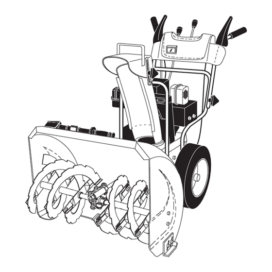
- Page 7 OPERATION KNOW YOUR SNOW THROWER READ THIS OWNER'S MANUAL AND ALL SAFETY RULES BEFORE OPERATING YOUR SNOW THROWER. Compare the illustrations with your snow thrower to familiarize yourself with the location of various controls and adjustments. Save this manual for future reference. These symbols may appear on your snow thrower or in literature supplied with the product.
- Page 8 OPERATION GAS O LINE ELECTRIC AUGER DISCHARGE CHUTE CONTROL LEVER FILLER CAP START BUTTON CONTROL LEVER TRACTION DRIVE SPEED RECOIL DRIVE MUF FLER CON TROL LEVER (AUXILIARY) CONTROL STARTER LEVER HANDLE CHUTE CHOKE DE FLEC TOR CON - TROL PRIM ER SAFETY IGNITION DISCHARGE...
- Page 9 OPERATION The operation of any snow thrower can result in foreign The DISTANCE that snow is thrown is controlled by the objects thrown into the eyes, which can result in severe eye position of the chute deflector. Set the deflector low to damage.
- Page 10 OPERATION After the packed snow has been dislodged, return the clean- CAUTION: Do not move speed con trol le ver out tool to it's mounting clip by pushing it into the clip. when traction drive control lever is en gaged. •...
-
Page 11: Before Starting The Engine
OPERATION BEFORE STARTING THE ENGINE TO START ENGINE Your snow thrower engine is equipped with both a 120 Volt CHECK ENGINE OIL LEVEL (See Fig. 15) A.C. electric starter and a recoil starter. The electric starter The engine on your snow thrower has been shipped, from is equipped with a three-wire power cord and plug and is the factory, already filled with oil. - Page 12 OPERATION 5. Pull recoil starter handle quickly. Do not allow starter SNOW THROWING TIPS rope to snap back. • Go slower in deep, freezing or heavy wet snow. Use 6. When the engine starts, release the recoil starter han dle the drive speed control, NOT the ON / OFF switch, to and slowly move the choke control to the “OFF”...
-
Page 13: Lubrication Chart
MAINTENANCE GENERAL REC OM MEN DA TIONS LUBRICATION CHART The warranty on this snow thrower does not cover items ➀ that have been sub ject ed to operator abuse or negligence. SAE 5W-30 Motor Oil To receive full value from the warranty, operator must ➁... - Page 14 MAINTENANCE BELTS TO CHANGE ENGINE OIL Check belts for deterioration and wear after every 50 hours Determine temperature range anticipated before next oil of operation and replace if necessary. The belts are not change. All oil must meet API service classification SG–SL. ad just able.
-
Page 15: Service And Adjustments
SERVICE AND ADJUSTMENTS To replace the capscrew/shear bolts: WARNING: To avoid serious injury, before 1. Disengage all controls and move throttle control to performing any service or ad just ments: STOP position. Wait for all moving parts to stop. 1. Be sure the on/off switch is in the 2. - Page 16 SERVICE AND ADJUSTMENTS TO REPLACE BELTS (See Fig. 18) 7. RELIEVE TENSION ON TRACTION DRIVE BELT IDLER and remove traction drive belt from around The auger and traction drive belts are not adjustable. If the pulleys. belts are damaged or begin to slip from wear, they should be replaced.
- Page 17 SERVICE AND ADJUSTMENTS TO REMOVE WHEELS (See Fig. 19) • Remove the klik pin and remove wheel from axle. IMPORTANT: When installing wheel, be sure to use the in- nermost hole in axle and the wheel hub hole. To dis en gage drive system from the wheels (for pushing or trans port ing the snow thrower), remove klik pin from wheel hub and insert pin into the outermost hole in axle only.
- Page 18 STORAGE Immediately prepare your snow thrower for storage at • Empty the fuel tank by starting the engine and letting it run until the fuel lines and car bu re tor are empty. the end of the season or if the unit will not be used for 30 days or more.
-
Page 19: Troubleshooting
TROUBLESHOOTING See appropriate section in manual unless directed to a qualified service centre. PROBLEM CAUSE CORRECTION Does not start 1. Fuel shut-off valve (if so 1. Turn fuel shut-off valve to OPEN position. equipped) in OFF position. 2. Safety ignition key 2. - Page 20 REPAIR PARTS AUGER HOUSING / IMPELLER ASSEMBLY SNOW THROWER - MODEL NO. 924SBb 924SBb (96193003500), PRODUCT NO. 961 93 00-35 2 (EXPLODED) 01.07.004-B NOTE: All component dimensions given in U.S. inches. 1 inch = 25.4 mm IMPORTANT: Use only Original Equipment Manufacturer (O.E.M.) replacement parts. Failure to do so could be hazardous, damage your snow thrower and void your warranty.
- Page 21 REPAIR PARTS AUGER HOUSING / IMPELLER ASSEMBLY SNOW THROWER - MODEL NO. 924SBb 924SBb (96193003500), PRODUCT NO. 961 93 00-35 PART DESCRIPTION 532 18 41-05 IMPELLER 532 19 67-10 GEARBOX ASSEMBLY 532 18 89-09 BEARING 532 19 10-79 IMPELLER PULLEY 532 17 53-22 DISCHARGE BASE 532 18 40-95...
- Page 22 REPAIR PARTS AUGER HOUSING / IMPELLER ASSEMBLY SNOW THROWER - MODEL NO. 924SBb 924SBb (96193003500), PRODUCT NO. 961 93 00-35 PART DESCRIPTION 532 40 78-80 AUGER HOUSING 532 40 78-25 SCRAPPER BAR 872 27 05-05 CARRIAGE BOLT 5/16−18 X .625 532 15 53-77 NUT 5/16−18 3 (5x)
- Page 23 REPAIR PARTS AUGER HOUSING / IMPELLER ASSEMBLY SNOW THROWER - MODEL NO. 924SBb 924SBb (96193003500), PRODUCT NO. 961 93 00-35 PART DESCRIPTION 532 18 81-70 PLASTIC RETAINER 532 41 18-33 AUGER BALL BEARING 532 17 95-82 SCREW 5/16−18 X 1.00 01.07.007-A PART DESCRIPTION...
- Page 24 REPAIR PARTS CONTROL PANEL / DISCHARGE CHUTE SNOW THROWER - MODEL NO. 924SBb 924SBb (96193003500), PRODUCT NO. 961 93 00-35 PART DESCRIPTION 532 40 76-50 CHUTE WELDMENT 532 18 41-13 DEFLECTOR WELDMENT 532 42 03-25 DEFLECTOR SEAL 532 18 41-14 STRAP 532 19 19-38 KNOB BLACK...
- Page 25 REPAIR PARTS CONTROL PANEL / DISCHARGE CHUTE SNOW THROWER - MODEL NO. 924SBb 924SBb (96193003500), PRODUCT NO. 961 93 00-35 PART DESCRIPTION 532 42 03-37 LEVER/CABLE ROTATOR ASSEMBLY 817 50 10-10 SCREW 10−24 X .625 01.09.007-A 532 42 06-78 ROTATOR HEAD 532 42 06-77 ROTATOR PIVOT BRACKET 532 42 06-75...
- Page 26 REPAIR PARTS HANDLES SNOW THROWER - MODEL NO. 924SBb 924SBb (96193003500), PRODUCT NO. 961 93 00-35 PART DESCRIPTION 532 42 10-69 PLOW HANDLE LH 532 42 10-70 PLOW HANDLE RH 532 19 69-44 PANEL BRACKET LH 532 19 69-43 PANEL BRACKET RH 532 19 95-13 HANDLE GRIP 874 78 05-12...
- Page 27 REPAIR PARTS HANDLES SNOW THROWER - MODEL NO. 924SBb 924SBb (96193003500), PRODUCT NO. 961 93 00-35 01.08.002-E PART DESCRIPTION 532 41 55-39 CONTROL PANEL 532 41 55-41 CONTROL LEVER LH 532 41 55-42 CONTROL LEVER RH 532 41 55-46 TRACTION ROD ARM 532 42 14-92 IMPELLER ROD ARM 532 41 26-77...
- Page 28 REPAIR PARTS HANDLES SNOW THROWER - MODEL NO. 924SBb 924SBb (96193003500), PRODUCT NO. 961 93 00-35 PART DESCRIPTION 532 18 04-80 IMPELLER ROD ASSEMBLY 532 40 57-40 TRACTION ROD ASSEMBLY 532 18 04-45 SHIFTER ROD TOP 532 18 77-16 SHIFTER ROD BOTTOM 532 18 04-47 SPRING SLEEVE 532 17 86-69...
- Page 29 REPAIR PARTS HANDLES SNOW THROWER - MODEL NO. 924SBb 924SBb (96193003500), PRODUCT NO. 961 93 00-35 PART DESCRIPTION 532 41 62-88 INTERLOCK SPRING 532 41 45-72 INTERLOCK CAM 532 17 88-31 TORSION SPRING 532 16 96-75 RETAINER 817 06 04-10 SCREW 1/4−20 X .625 532 42 18-14 INTERLOCK STOP...
- Page 30 REPAIR PARTS DRIVE SNOW THROWER - MODEL NO. 924SBb 924SBb (96193003500), PRODUCT NO. 961 93 00-35 01.02.008-A_Sheet_2 NOTE: All component dimensions given in U.S. inches. 1 inch = 25.4 mm IMPORTANT: Use only Original Equipment Manufacturer (O.E.M.) replacement parts. Failure to do so could be hazardous, damage your snow thrower and void your warranty.
- Page 31 REPAIR PARTS DRIVE SNOW THROWER - MODEL NO. 924SBb 924SBb (96193003500), PRODUCT NO. 961 93 00-35 PART DESCRIPTION 532 19 84-74 SPEED SELECTOR HEAD ASSEMBLY 817 50 10-10 SCREW 10−24 X .625 532 19 77-63 DRIVE PLATE WELDMENT 532 19 77-64 HEX SHAFT 532 17 53-44 TRUNNION BEARING ASSEMBLY...
- Page 32 REPAIR PARTS DRIVE SNOW THROWER - MODEL NO. 924SBb 924SBb (96193003500), PRODUCT NO. 961 93 00-35 01.02.008-A_Sheet_1 PART PART DESCRIPTION DESCRIPTION 817 49 05-08 BOLT 5/16−18 X .500 532 18 00-82 INTERMEDIATE GEAR 532 75 11-53 NUT 5/16−18 532 18 01-34 AUXILIARY SHAFT 532 18 00-17 FLANGE BEARING...
- Page 33 REPAIR PARTS DRIVE SNOW THROWER - MODEL NO. 924SBb 924SBb (96193003500), PRODUCT NO. 961 93 00-35 01.03.004-B PART DESCRIPTION 532 18 82-26 (assy of 1a,1b) AXLE ASSEMBLY 532 17 93-52 AXLE SHAFT 532 18 42-06 ROLL PIN 3/16 532 18 00-81 GEAR 532 17 46-97 THRUST WASHER...
- Page 34 REPAIR PARTS CHASSIS / ENGINE / PULLEYS SNOW THROWER - MODEL NO. 924SBb 924SBb (96193003500), PRODUCT NO. 961 93 00-35 01.00.017-B PART DESCRIPTION - - - - - - - - - ENGINE, B & S MODEL 15C114-1235-E8 532 41 53-40 FRAME 532 41 08-77 BOTTOM PAN 532 42 38-70 ENGINE MOUNT PLATE 532 15 04-06 BOLT 3/8−16...
- Page 35 REPAIR PARTS CHASSIS / ENGINE / PULLEYS SNOW THROWER - MODEL NO. 924SBb 924SBb (96193003500), PRODUCT NO. 961 93 00-35 PART DESCRIPTION 532 19 22-13 COVER ASSEMBLY 532 17 91-57 PULLEY 532 41 97-44 TRACTION BELT 532 40 80-07 IMPELLER BELT 01.04.003-A NOTE: All component dimensions given in U.S.
- Page 36 REPAIR PARTS WHEELS SNOW THROWER - MODEL NO. 924SBb 924SBb (96193003500), PRODUCT NO. 961 93 00-35 PART DESCRIPTION 532 42 17-30 WHEEL ASSEMBLY LH 532 42 17-31 WHEEL ASSEMBLY RH 01.06.002-A NOTE: All component dimensions given in U.S. inches. 1 inch = 25.4 mm IMPORTANT: Use only Original Equipment Manufacturer (O.E.M.) replacement parts.
- Page 37 REPAIR PARTS BAG OF PARTS SNOW THROWER - MODEL NO. 924SBb 924SBb (96193003500), PRODUCT NO. 961 93 00-35 PART DESCRIPTION 532 19 85-63 POWER CORD 532 16 96-75 RETAINER PIN 532 18 06-84 WRENCH 873 80 06-00 LOCKNUT 3/8−16 819 13 13-16 WASHER 3/8 532 19 86-36 SHEAR BOLT 1/4−20 X 1−3/4...
- Page 38 532 42 37-06 DECAL, HUSQVARNA 532 18 10-35 DECAL, DANGER, DEFLECTOR 532 18 10-42 DECAL, DANGER 532 42 37-05 DECAL, HUSQVARNA, 924SBb 532 18 10-33 DECAL, INSTRUCTION 532 41 53-91 DECAL, TRACTION LEVER 532 41 53-90 DECAL, AUGER LEVER 532 41 54-75...
- Page 39 SERVICE NOTES...
- Page 40 532 42 35-22 Rev. 2 10.14.08 SR Printed in the U.S.A.