Table of Contents
Advertisement
Advertisement
Table of Contents

Related Manuals for Lab.gruppen fP Series FP 6400


Summary of Contents for Lab.gruppen fP Series FP 6400
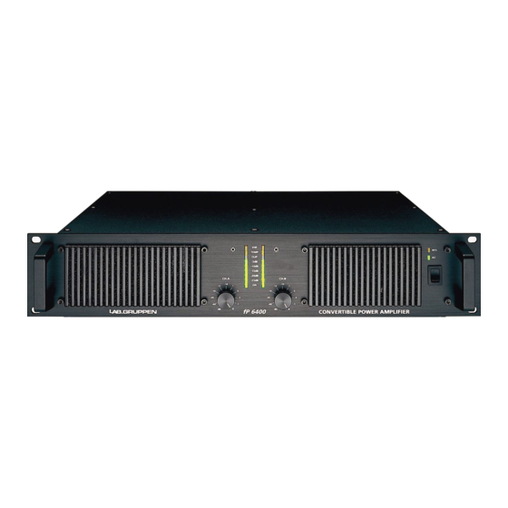
- Page 1 Ñm=SQMM= rpbo=j^kr^i=...
-
Page 2: Table Of Contents
N= `lkqbkqp= CONTENTS ...1 APPROVALS...2 WARNINGS ...2 Explanation of graphical symbols ...2 WARNING...2 CAUTION ...2 Important Safety Instructions ...2 User responsibility...3 3.5.1 Speaker damage...3 3.5.2 Speaker output hazard ...3 3.5.3 Radio interference ...3 INTRODUCTION...4 Unpacking ...4 Front Panel ...4 Rear Panel...5 REAR PANEL FEATURES ...6 Gain switch...6 5.1.1... -
Page 3: Warnings
9.1.4 Short circuit protection ...16 9.1.5 Automatic Fuse Saver, AFS 9.1.6 AC mains voltage protection ...16 9.1.7 The “AC” LED ...17 9.1.8 DC protection ...17 MAINTENANCE...17 10.1 Troubleshooting...17 SPECIFICATIONS ...18 WARRANTY...19 O= =^mmols^ip= This equipment conforms to the requirements of the EMC directive 89/336/EEC, amended by 92/31/EEC and 93/68/EEC and the requirements of the Low Voltage Directive 73/23/EEC, amended by 93/68/EEC. -
Page 4: Caution
7. Do not operate the amplifier near heat producing devices such as radiators, heat registers, stoves or other apparatus that produce heat. 8. Always operate the unit with the chassis ground wire connected to the electrical safety earth. Do not defeat the safety purpose of a grounding-type plug. A grounding type plug has two pins and a third grounding prong. -
Page 5: Front Panel
QKN= råé~ÅâáåÖ= Carefully open the shipping carton and check for any noticeable damage. Every Lab.gruppen amplifier is tested and inspected before leaving the factory and should arrive in perfect condition. If found to be damaged, notify the shipping company immediately. -
Page 6: Rear Panel
4. VHF protect indicator This indicator illuminates if signals above 12 kHz are continuously present at full power at the output terminals. If this occurs the input signal is muted, and the process cycles until the VHF signal is no longer present. -
Page 7: Gain Switch
7. Link/Bridge switch Two of the switches in the DIP switch are used for Link and Bridge operation. (See page 6) 8. Gain switch channel A Three of the switches in the DIP switch selects the maximum gain of the channel to be either 20, 23, 26, 29, 32, 35, 38 or 41dB. -
Page 8: Options
RKNKP= léíáçåë= As the DIP switch is recessed, one may put a sticker across the bay to prevent from unauthorized changes. Another option is to completely remove the DIP switch. This should be done by authorized service personnel only! It corresponds to all switches set to “off”, i.e. 32dB gain and stereo mode. RKO= iáåâ=ëïáíÅÜ= The Link switch located on the rear panel (in the centre of the DIP switch) is for changing the operation mode of the amplifier (see next section 5.3). -
Page 9: Bridge Mono Mode
RKPKQ= _êáÇÖÉ=ãçåç=ãçÇÉ= The Bridge mono mode is used to deliver both channels' power to a single load. The nominal impedance of the load must be more than 3 ohms. Set the Link switches to the “On” position and use one of the input connectors. - Page 10 MLS to a lower value. If you reduce the amp’s output power by choosing lower MLS values, you only reduce the maximum output voltage. In fact, you will get more current headroom for low impedance loads.
-
Page 11: The Solution
The amplifier uses a forced air cooling system to maintain a low and even operating temperature. All fan-cooled Lab.gruppen amplifiers have front to rear airflow. There are several reasons for this, one being that there is usually cooler air outside the rack than inside, and therefore the amplifiers can run at higher continuous power levels without thermal problems. -
Page 12: Grounding
The warranty will not cover damage caused by connecting to the wrong type of AC mains. Lab.gruppen switch mode amplifiers use primary switching. The mains power is being rectified directly in front of the transformer, meaning that the power supply is insensitive to the mains frequency and will operate from DC to 400 Hz. -
Page 13: Power Consumption
long-term current draw. Read more about the AFS limiter under “Protection” on page 16. There is also a Technical Note on our website www.labgruppen.com: AFS limiting and power consumption. It is more useful to state the current draw in different loads and output power levels. These figures can be found on the specification sheet. -
Page 14: Connections
T= `lkkb`qflkp= TKN= fåéìí=ÅçååÉÅíáçåë= TKNKN= _~ä~åÅÉÇ=áåéìíë= The XLR input connectors are electronically balanced, and wired according to the IEC 268 (pin 2 = “hot”), and wired in the following way: PIN 1 GROUND/SHIELD PIN 2 HOT (+) PIN 3 COLD (-) Figure 4: XLR input connector Within the Neutrik®... -
Page 15: Speaker Damage
They are wired in the following manner: The right jack, Channel A, provides both channel A and B outputs, so it is useful for bridge and bi-amp operation (see bridge mono operation on page 7). The left Speakon, Channel B, carries only the channel B output. -
Page 16: Indicators
The green bottom ”ON” LED’s indicate that the output circuits are receiving the correct rail voltage. V= molqb`qflk=cb^qrobp= Each Lab.gruppen amplifier has many advanced protection features. Should a fault condition arise they are protecting both, the amplifier and the speakers connected to it. Under normal use these features are inaudible. -
Page 17: Thermal Protection
VHF protection will re-initiate. VKNKQ= pÜçêí=ÅáêÅìáí=éêçíÉÅíáçå= All Lab.gruppen amplifiers are completely short circuit protected. The protection circuitry permits very high peak currents, but still holds the output devices within the safe operation levels. If a short circuit remains to be present, the channel effected will eventually go into thermal protect cycle until the short circuit has been removed. - Page 18 In the unlikely event of on a non-user-rectifiable fault return the amplifier to your supplier, or an approved service centre. Lab.gruppen cannot be held responsible for damage or injury as a result of the top or bottom cover being removed.
- Page 19 NN=pmb`fcf`^qflkp= i~ÄKÖêìééÉå== ======================== rëÉê=j~åì~ä===Ñm=SQMM======sÉêëáçå=NKN========OMMPJNMJMO=...
- Page 20 NO=t^oo^kqv= General This product is manufactured by Lab.gruppen and is warranted to be free from defects in components and factory workmanship under normal use and service for a period of three (3) years from the date of original purchase from an authorised Lab.gruppen dealer.