Table of Contents
Advertisement
Quick Links
Advertisement
Table of Contents

Related Manuals for Foxconn Z75M-S Series


Summary of Contents for Foxconn Z75M-S Series
- Page 1 H61MXE Series Motherboard Z75M-S Series Motherboard User’s Manual...
-
Page 2: More Information
Statement: This manual is the intellectual property of Foxconn, Inc. Although the information in this manual may be changed or modified at any time, Foxconn does not obligate itself to inform the user of these changes. Trademark: All trademarks are the property of their respective owners. Version: User’s Manual V1.0 for Z75M-S motherboard. Symbol description: Caution: refers to important information that can help you to use motherboard better, and tells you how to avoid problems. -
Page 3: Declaration Of Conformity
Declaration of conformity HON HAI PRECISION INDUSTRY COMPANY LTD 66 , CHUNG SHAN RD., TU-CHENG INDUSTRIAL DISTRICT, TAIPEI HSIEN, TAIWAN, R.O.C. declares that the product Motherboard Z75M-S is in conformity with (reference to the specification under which conformity is declared in accordance with 89/336 EEC-EMC Directive) ■ EN 55022: 1998/A2: 2003 Limits and methods of measurements of radio disturbance characteristics of information technology equipment ■ EN 61000-3-2/:2000... - Page 4 Declaration of conformity Trade Name: FOXCONN Model Name: Z75M-S Responsible Party: PCE Industry Inc. Address: 458 E. Lambert Rd. Fullerton, CA 92835 Telephone: 714-738-8868 Facsimile: 714-738-8838 Equipment Classification: FCC Class B Subassembly Type of Product: Motherboard Manufacturer: HON HAI PRECISION INDUSTRY COMPANY LTD Address: 66 , CHUNG SHAN RD., TU-CHENG INDUSTRIAL DISTRICT, TAIPEI HSIEN, TAIWAN, R.O.C.
-
Page 5: Installation Precautions
Installation Precautions ■ Electrostatic discharge (ESD) is the sudden and momentary electric current that flows between two objects at different electrical potentials. Normally it comes out as a spark which will quickly damage your electronic equipment. Please wear an electrostatic discharge (ESD) wrist strap when handling components such as a motherboard, CPU or memory. -
Page 6: Table Of Contents
TAblE of CoNTENTS Chapter 1 Product Introduction Product Specifications ................2 Layout.......................4 Back Panel Connectors ................5 Chapter 2 Hardware Install Install the CPU and CPU Cooler ..............8 Install the Memory .................. 11 Install an Expansion Card ..............13 Install other Internal Connectors ............14 Jumpers ....................18 OnBoard Button..................19 OnBoard Debug LED ................19... - Page 7 Create a RAID Driver Diskette ...............68 BIOS Configuration ................70 Create RAID in BIOS................70 Install a New Windows XP ..............96 Chapter 6 Appendix USB Charger Introductio ..............100 Intel Rapid Start Technology ® .............101 Technical Support : Support Website : http://www.foxconnchannel.com Support Website : http://www.foxconnsupport.com Worldwide online contact Support : http://www.foxconnsupport.com/inquiry.aspx...
-
Page 8: Product Specifications
Thank you for buying Foxconn Z75M-S motherboard. Foxconn products are engineered to maximize computing power, providing only what you need for break-through performance. This chapter includes the following information: ■ Product Specifications ■ Layout ■ Back Panel Connectors... - Page 9 1-1 Product Specification Support Intel Ivy Bridge/Sandy Bridge LGA 1155 Processors, Max processor power up to 95W For the latest CPU information, please visit: http://www.foxconnsupport.com/cpusupportlist.aspx Intel Chipset ® 4 x 240 pin DDR3 DIMMs Memory Support up to 32GB of system memory Dual channel DDR3 2133(oc*)/ 1866(oc*) /1600(oc*) /1333 MHz architecture (oc*) = overclocking 1 x PCI Express x 16 slot Expansion Slots 2 x PCI Express x1 slots...
- Page 10 1 x Front audio header 1 x Speaker header (Buzzer Reserved) 1 x Clear CMOS header 1 x TPM header 1 x CIR header (Only support under Win 7) 1 x Intrusion Alarm header 1 x SPDIF OUT header 1 x COM header 1 x PS/2 Keyboard port Back Panel Connectors...
-
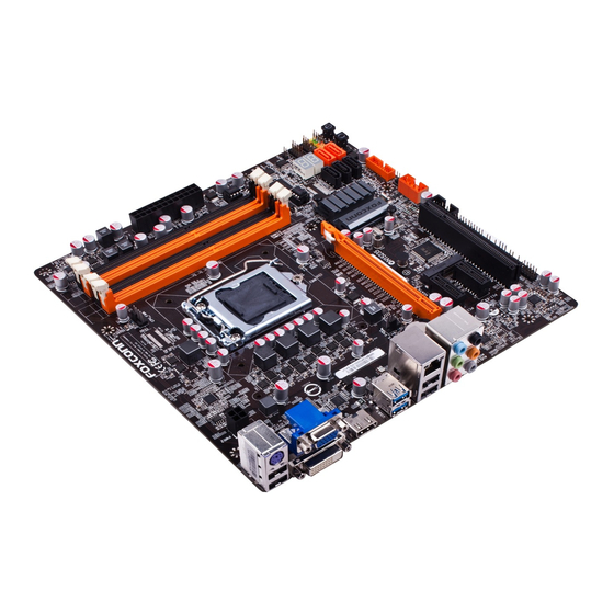
Page 11: Layout
1-2 layout 1. 4-pin ATX 12V Power Connector 14. Reset button 2. 4-pin SYS_FAN1 Header 15. Power On/Off button 3. PCI Express x16 Slot 16. Front Panel Header 4. PCI Express x1 Slots 17. CIR Header 5. PCI Slots 18. COM1 Header 19. INTR Header 6. Front Audio Header 20. Debug LED 7. SPDIF_OUT Header 21. Clear CMOS Header 8. 3-pin SYS_FAN1 Header 22. 24-Pin ATX Power Connector... -
Page 12: Back Panel Connectors
1-3 back Panel Connectors PS/2 Keyboard Port VGA Port DVI-D Port HDMI Port LAN Port Line Out Line In Rear Speaker Subwoofer Side Speaker Microphone In USB Ports Audio Ports USB 3.0 Ports 1. PS/2 Keyboard Port Use the upper port to connect a PS/2 keyboard. 2. VGA Port To connect with external display devices, such as monitor or LCD display. 3. - Page 13 8. Audio Ports For the definition of each audio port, please refer to the table below : 6-channel Audio ports Port 2-channel 4-channel 5.1-channel Blue Line In Rear Speaker Out* Rear Speaker Out* Green Line Out Front Speaker Out Front Speaker Out Pink Microphone In Microphone In Center/Subwoofer Out* * : Please refer to Chapter 4, and install the Realtek audio driver (in CD) to assign the audio output ports for different applications of 2/4/5.1 channels. The fundamental audio outputs are depicted in the table above.
- Page 14 This chapter introduces the hardware installation process, including the installation of the CPU, memory, power supply, slots, pin head- ers and the mounting of Clear CMOS. Caution should be exercised during the installation of these modules. Please refer to the moth- erboard layout prior to any installation and read the contents in this chapter carefully.
-
Page 15: Install The Cpu And Cpu Cooler
2-1 Install the CPU and CPU Cooler Read the following guidelines before you begin to install the CPU : ■ Make sure that the motherboard supports the CPU. ■ Always turn off the computer and unplug the power cord from the power supply before installing the CPU to prevent hardware damage. ■ Locate the pin one of the CPU. The CPU cannot be inserted if oriented incorrectly. (Or you may locate the notches on both sides of the CPU and alignment keys on the CPU socket.) ■ Apply an even and thin layer of thermal grease on the surface of the CPU. - Page 16 Follow the steps to install the CPU onto the CPU socket : Before installing the CPU, make sure to turn off the computer and unplug the power cord from the power outlet to prevent damage to the CPU. 1. Release the CPU socket lever. 2. Lift the metal cover on the CPU socket.
-
Page 17: Install The Cpu Cooler
Install the CPU Cooler Follow the steps below to correctly install the CPU cooler on the motherboard. 1. Apply and spread an even ther- 2. Place the four bolts of the CPU mal grease on the surface of CPU. cooler to the holes of the mother- board, push them straight down from the top, and the bolts will be fas- tened on the motherboard. -
Page 18: Install The Memory
2-2 Install the Memory Read the following guidelines before you begin to install the memory : ■ Make sure that the motherboard supports the memory. It is recommended that memory of the same capacity, brand, speed, and chips be used. ■ Always turn off the computer and unplug the power cord from the power outlet before installing the memory to prevent hardware damage. ■ Memory modules have a foolproof design. A memory module can be installed in only one direction. -
Page 19: Installing A Memory
Installing a Memory Before installing a memory module, make sure to turn off the computer and unplug the power cord from the power outlet to prevent damage to the memory module. Be sure to install DDR3 DIMMs on this motherboard. Notch If you take a look at front side of memory module, it has asymmetric pin counts on both sides sepa- rated by a notch in the middle, so it can only fit in one direction. Follow the steps below to correctly... -
Page 20: Install An Expansion Card
2-3 Install an Expansion Card ■ Make sure the motherboard supports the expansion card. Carefully read the manual that came with your expansion card. ■ Always turn off the computer and unplug the power cord from the power outlet before installing an expansion card to prevent hardware damage. PCI Express x16 PCI Express x1 follow the steps below to correctly install your expansion card in the expansion slot. 1. -
Page 21: Install Other Internal Connectors
2-4 Install other Internal Connectors Power Connectors This motherboard uses an ATX power supply. In order not to damage any device, make sure all the devices have been installed properly before applying the power supply. 24-pin ATX Power Connector : PWR1 PWR1 is the ATX power supply connector. - Page 22 Audio Connector : f_AUDIo The audio connector supports HD Audio standard. It A_MIC2_L AUD_GND provides the Front Audio output choice. A_MIC2_R PRESENCEJ A_LINE2_R SENSE1_RETURN SENSE_SEND EMPTY A_LINE2_L SENSE2_RETURN F_AUDIO S/PDIf Header: SPDIf_oUT The connector is used for S/PDIF output. EMPTY SPDIF_OUT SPDIF_OUT Speaker Connector : SPEAKER...
- Page 23 TPM Header : TPM1 The TPM (Trusted Platform Module) provides the ability to the PC to run applications more secure and LCLK LFRAMEn EMPTY to make transactions and communication more trust- LRESETn NC_3 worthy. To utilize this function, you should purchase LAD3 LAD2 LAD1...
- Page 24 Power lED Connector (PWR-lED) Connect to the power LED indicator on the front panel of the chassis. The Power LED indicates the system’s status. When the system is in op- eration (S0 status), the LED is on. When the system gets into sleep mode (S1) , the LED is blinking; When the system is in S3/S4 sleep state or power off mode (S5), the LED is off. This 2-pin connector is directional with +/- sign.
-
Page 25: Jumpers
2-5 Clear CMoS Clear CMoS Header: ClR_CMoS The motherboard uses CMOS RAM to store the basic hardware information (such as BIOS data, date, time information, hardware password...etc.). Clear CMOS data is the fast way to go back to factory default when the BIOS settings were mistakenly modified. The steps to clear CMOS data are : 1. -
Page 26: Onboard Button
2-6 onboard button Power on button: PWR_oN Push the power on button to power on the system. Reset button: RST Push the reset button to reboot the system. PWR_ON 2-7 OnBoard Debug LED 2-digital LED readout displays hardware status and enables quick error diagnosis. -
Page 27: Chapter 3 Bios Setup
This chapter tells how to change system settings through the BIOS Setup menus. Detailed descriptions of the BIOS param- eters are also provided. You have to run the Setup Program when the following cases occur : 1. An error message appears on the screen during the system Power On Self Test (POST) process. -
Page 28: Enter Bios Setup
Enter bIoS Setup The BIOS is the communication bridge between hardware and software, correctly setting up the BIOS parameters is critical to maintain optimal system performance. Power on the computer, when the message "Press <DEl> to enter Setup, <f7> to boot Menu" appears at the bottom of the screen, you can press <DEL>... -
Page 29: Main
Main Aptio Setup Utility - Copyright (C) 2011 American Megatrends, Inc. Main Main Advanced OC Plus Boot Security Save & Exit Set the Date. Use Tab to BIOS Information BIOS Vendor American Megatrends switch between Date elements. BIOS Build Date 02/21/2012 15:48:17 Embedded Control Version 12.F1.10... -
Page 30: Advanced
Advance Aptio Setup Utility - Copyright (C) 2011 American Megatrends, Inc. Main Advanced Advanced OC Plus Boot Security Save & Exit Enabled/Disabled Boot Option Legacy OpROM Support for Legacy Network Devices. Launch PXE OpROM [Disabled] Launch Storage OpROM [Enabled] ▶ Onboard Device Configuration ▶... -
Page 31: Chipset Configuration
► LAN Controller This item is used to enable or disable the onboard LAN controller. ► Azalia HD Audio This item is used to enable or disable the Azalia HD Audio Controller. ► Serial Port This item is used to enable or disable serial port (COM1). ► Change Serial Port Setting This item is used to select an optimal setting for super IO device. -
Page 32: Pci Express Settings
PCI Express Settings Aptio Setup Utility - Copyright (C) 2011 American Megatrends, Inc. Advanced PCI Express Device Register Settings Enables or Disables PCI Express Device No Snoop option. No Snoop [Enabled] Maximum Payload [Auto] Maximum Read Request [Auto] PCI-E1_16X Slot ASPM Support [Disabled] PCI-E1_1X Slot ASPM Support [Disabled]... -
Page 33: Acpi Configuration
ACPI Configuration Aptio Setup Utility - Copyright (C) 2011 American Megatrends, Inc. Advanced ACPI Configuration Select the hignest ACPI sleep state the system will enter ACPI Sleep State [S3 (Suspend to RAM)] when the SUSPEND button is pressed. Lock Legacy Resources [Disabled] S3 Video Repost [Disabled]... -
Page 34: Sata Configuration
This item is used to control the wake on USB device function from S1/S3/S4 State. When you set ‘Deep Sleep Mode’ to [Enabled] and set this item to [Enabled], only S1/S3 state can tate. ► Wake on PCI/PCIe Device This item is used to control the wake on PCI/PCIe device from S3/S4/S5/G3 function and S1 not support wake. When you set ‘Deep Sleep Mode’ to [Enabled] and set this item to [Ena- bled], only S3 state can be wake up. ► Wake on PS/2 KB from S1 and S3 This item is used to enable or disable PS2 key board wake up from S1 and S3 state. SATA Configuration Aptio Setup Utility - Copyright (C) 2011 American Megatrends, Inc. Advanced SATA Configuration (1) IDE Mode. (2) AHCI Mode. SATA Controller(s) [Enabled] (3) RAID Mode. SATA Mode Selection [AHCI] Enabled onboard SATA RAID... -
Page 35: Usb Configuration
► Serial ATA Port 0/1/2/3/4/5 This item shows the SATA device information connected to Port 0/1/2/3/4/5. ► Hot Plug (Appears when “SATA Mode” is set to [RAID]/[AHCI) The hot plug function allows for device detection without power being applied and ability to connect and disconnect devices without prior notification to the system. This item is used to enable or disable hot plug function for SATA hard disks when in RAID/AHCI mode. ► External SATA (Appears when “SATA Mode” is set to [AHCI]) This item is used to allow an outside the box connection of up to 2 meters (when using the cable defined in SATA-IO) or not. ► Spin up Device(Appears when “SATA Mode” is set to [AHCI]) This item is used to select if the SATA controller supports staggered spin-up on its ports, for use in balancing power spikes. - Page 36 value is [20 sec]. ► Device reset time-out This item is used to select the USB mass storage device start unit command time-out. Default value is [20 sec]. ► Device power-up delay This item is used to set the maximum time the device will take before it can report itself to the host controller.
-
Page 37: Oc Plus
oC Plus Aptio Setup Utility - Copyright (C) 2011 American Megatrends, Inc. Main Advanced OC Plus Boot Security Save & Exit OC Plus OC Plus Bclock (FSB) CPU Bclock Override (1/100 MHz) 10000 Override setting. ▶ CPU Configuration ▶ Memory Configuration ▶... - Page 38 This item is used to select the number of cores to enable in each processor package. ► VID Override for Max Turbo Ratio This item is used to set VID override for max Turbo Ratio in 1/256 volts. ► IA Core Current Max(1/8 Amp) This item is used to set IA Core current max value for factory long duration power limit. Default value is get from CPU MSR. ► iGFX Core Current Max(1/8 Amp) This item is used to set iGFX Core current max value for factory long duration power limit.
-
Page 39: Memory Configuration
Virtualization (i.e. Intel ® Vanderpool Technology) allows a platform to run multiple operating systems and applications in independent partitions or “containers.” One physical compute system can function as multiple “virtual” systems. Vanderpool Technology can help improve future virtualization solutions. This item will be displayed only when the CPU is supporting this feature and the setting is used to enable/disable it. - Page 40 [XMP Profile 1]-Configuration database of using XMP timing profile 1. [XMP Profile 2]- Configuration database of using XMP timing profile 1. The following items appear only when the option is set to “Manual”. ► Memory Clock Multiplier This item is used to set the memory clock multiplier. ► Memory Multiplier This item is used to set the memory multiplier ratio. ► CAS# Latency(tCL) This item dispalys the CAS Latency time. The CAS Latency is the number of clock cycles that elapse from the time the request for data is sent to the actual memory location until the data is transmitted from the module.
-
Page 41: Voltage Configuration
Voltage Configuration Aptio Setup Utility - Copyright (C) 2011 American Megatrends, Inc. OC Plus Voltage Configuration The minimum available for adjustment is 1.307V. The maximum available for DRAM Voltage [Default] CPU VSA Voltage [Default] adjustment is 2.006V. The default voltage is 1.553V. PCH Core Voltage [Default] CPU VTT (Uncore) Voltage... -
Page 42: Hardware Monitor
Hardware Monitor Aptio Setup Utility - Copyright (C) 2011 American Megatrends, Inc. OC Plus Hardware Monitor Case Intrustion Alert [Disabled] CPU FAN Mode [Automatic Mode] FAN Off Temp Limit FAN Start Temp Limit FAN Start PWM PWM Slope Setting [0.5 PWM] CPU Temperature : +255 C CPU FAN Speed... - Page 43 This item is used to select the CPU VTT (Uncore) voltage. [Default] means the voltage is according to your CPU model. ►DDR3 Memory Voltage This item shows the Current DDR3 Memory Voltage. ►PCH Voltage This item shows the Current PCH Voltage. ►Battery 3V Voltage This item shows the Current Battery 3V Voltage. ►PSU Stand By 3.3V Rail This item shows the Current PSU Stand By 3.3V Rail Voltage.
-
Page 44: Boot
boot Aptio Setup Utility - Copyright (C) 2011 American Megatrends, Inc. Main Advanced OC Plus Boot Boot Security Save & Exit Boot Configuration Select the keyboard NumLock Bootup Numlock State [On] state Quiet Boot [Enabled] Fast Boot [Enabled] UEFI Boot [Disabled] Set Boot Priorities 1st Boot... -
Page 45: Security
Security Aptio Setup Utility - Copyright (C) 2011 American Megatrends, Inc. Main Advanced OC Plus Boot Security Save & Exit Set User Password. Password Description If ONLY the Administrator’s password is set, then this only limits access to Setup and is only asked for when entering Setup. -
Page 46: Save & Exit
Save & Exit Aptio Setup Utility - Copyright (C) 2011 American Megatrends, Inc. Main Advanced OC Plus Boot Security Save & Exit Save & Exit Save Changes and Exit Set Administrator Password Discard Changes and Exit Save Changes and Reset Discard Changes and Reset Save Options Save Changes... - Page 47 Select <Yes> and then press <Enter> to load the defaults. Select <No> and press <Enter>, it will not load. By this default, BIOS have set the optimal performance parameters of system to improve the performances of system components. But if the optimal performance parameters to be set cannot be supported by your hardware devices (for example, too many expansion cards were installed), the system might fail to work.
- Page 48 The utility CD that came with the motherboard contains useful software and several utility drivers that enhance the motherboard features. This chapter includes the following information: ■ Install driver and utility ■ FOX ONE ■ FOX LiveUpdate ■ FOX LOGO ■ FOX DMI Note : Because each module is independent, so the section number will be reorganized and unique to each module, please understand.
-
Page 49: Install Driver And Utility
Manual Installation Step by Step Automatic Installa- tion by One Click Drop to System Tray Exit the program Visit Foxconn's Show Utilities Show Drivers Browse CD View the User’s Manual Website Choose the items you want to Install... - Page 50 2. Utility Use these options to install additional software programs. And click “User’s Manual“ button to view the product manual. The Driver and Utility items displayed above represent a Windows 7 based system. The appearance may change with different Operating Systems.
-
Page 51: Fox One
foX oNE FOX ONE is a powerful utility for easily modifying system settings. It also allows users to monitor various temperature values, voltage values, frequencies and fan speeds at any time. With FOX ONE, you can : ■ Monitor hardware temperatures, voltages, frequencies and fan speeds. Supporting Operating Systems : ■ Windows XP (32-bit and 64-bit) ■ Windows 7 (32-bit and 64-bit) Depending on hardware support, voltage monitoring and Fox Intelligent Stepping... -
Page 52: Main Page
1. Main Page Show CPU Toolbar Information Alert Lamp Switch Button Skin Button Exit Minimum Configuration Homepage Monitor Frequency/Voltage/Fan speed/Temperature value Toolbar Use the toolbar to navigate to other pages. Alert lamp When the system is in healthy state, the color of alert lamp is green. When the system is in abnormal state, the alert lamp color is red. - Page 53 Click this button to exit the program. Minimum Click this button to drop the FOX ONE to Windows system tray located at the lower right corner of your screen. Homepage Click this button to visit Foxconn motherboard website : http://www.foxconnchannel.com...
- Page 54 Configuration This menu allows you to configure : 1). Monitor interval (ms) : This is to define the interval of different messages of system settings which are to be displayed on Simple Mode screen. Minimum value is 1 second. 2). Simple Mode : To select which message of system settings are to be displayed in the Simple Mode. Messages such as CPU frequency, voltage...etc., they can be displayed one by one in Simple Mode.
- Page 55 Step 1 : Click Calibration icon, a message pops out to ask for continue. Select Yes. Step 2 : After data is collected, it will ask you to restart your computer now. Later on, when the FOX ONE program is activated, and F.I.S. feature (in CPU Page) is also enabled, FOX ONE will automatically adjust your CPU clock according to your system loadings.
-
Page 56: Limit Setting
2. Limit Setting 2.1 Limit Setting - CPU Temperature This page lets you to set CPU high limit temperature and enable the alert function. Go to Limit Show current CPU Setting page temperature value Enable alert function when the CPU temperature is higher than high limit value Show current high limit value of the CPU temperature... - Page 57 2.2 Limit Setting - System Temperature This page lets you to set system high limit temperature and enable the alert function. Show current system temperature value Enable alert function when the system temperature is higher than high limit value Show current high limit value of system temperature Set high limit by dragging the lever...
- Page 58 2.4 Limit Setting - System Fan This page lets you to set system fan low limit rpm and enable the alert function. Show current system fan rpm value Enable alert function when the system fan runs slower than low limit rpm value Show current low limit rpm value of system Set low limit rpm by dragging the lever...
-
Page 59: Fan Control
3. Fan Page - Fan Control This page lets you enable Smart Fan function or set the fan speed by manual. When Smart Fan is selected, you must use a 4-pin CPU cooler in your system. Go to Fan page Enable or disable smart fan function Set fan speed by dragging the lever Apply the changes... -
Page 60: Fox Liveupdate
FOX LiveUpdate FOX LiveUpdate is a useful utility to backup and update your system BIOS, drivers and utilities by local or online. Supporting Operating Systems : ■ Windows XP (32-bit and 64-bit) ■ Windows 7 (32-bit and 64-bit) Using FOX LiveUpdate : 1. local Update 1-1 local Update - bIoS Information This page lets you know your system BIOS information. - Page 61 1-2 local Update - backup This page can backup your system BIOS. You can click “Backup”, and key in a file name, then click “Save” to finish the backup operation. Make sure you can remember the file name together with the directory which it is stored, prevented that you may need them to recover your BIOS later. 1-3 local Update - Update Key in a BIOS name Click here This page helps you to update your BIOS from a local file. After click “Update”, An alert message will be displayed to ensure if you really want to continue, click “Yes” to confirm. A setup wizard will guide you to load a local BIOS file to finish the operation. You must remember from which directory to load your new BIOS file before the setup wizard starts. FOX LiveUpdate can automatically backup old BIOS before update. This feature can be enabled in the "Configure-System" setup. Please refer to "Configure-System" section for more detail. The default backup directory is C:\LiveUpdate_Temp, but the backup file name will be automatically generated. It is hard to find it out from a backup directory,...
-
Page 62: Online Update
2. online Update 2-1 online Update - Update bIoS This page lets you update your system BIOS from Internet. Click “start”, it will search the new BIOS from Internet. Then follow the wizard to finish the update operation. Click here Current information Search new BIOS from Internet Select BIOS to update Browse detailed information Update BIOS... - Page 63 Select the driver to update Browse detailed information Install the selected driver Close the window 2-3 online Update - Update Utility This page lets you update utilities from Internet. Click “start”, it will search the new utilities from Internet. Then follow the wizard to finish the update operation. Click here Current information Search new utilities from Internet...
- Page 64 2-4 online Update - Update All This page lets you update your system drivers from Internet. Click “start”, it will search all new BIOS/drivers/utilities from Internet. Then follow the wizard to finish the update operation. Click here Current information Search all new BIOS/ drivers/utilities from Internet Browse detailed BIOS information Browse detailed driver information Browse detailed utility information...
-
Page 65: Configure
3. Configure 3-1 Configure - option This page lets you set auto search options. After you enable the auto search function, FOX LiveUpdate will start its searching from Internet and if any qualified item found, it will pop out a message on the task bar to inform you to do the next step. Click here Set auto search options Set auto search the latest... - Page 66 When you enable "Auto Search FOX LiveUpdate", if your FOX LiveUpdate version is older, it will auto search from internet and prompt you to install the new version. Prompt you to install the new FOX LiveUpdate 3-2 Configure - System This page lets you set the backup BIOS location and determine if the FOX LiveUpdate can auto run when the system starts up.
-
Page 67: About & Help
3-3 Configure - Advance This page lets you select to flash BIOS / Boot Block and clear CMOS. If you choose Flash Boot Block, it means BIOS is not protective, and you must make sure the flash process is continuous and without any interruption. Click here Select which BIOS ROM to flash(Only available to motherboard with backup BIOS ROM ) Select to flash Boot Block Select to clear CMOS Apply the changes Reset to default value We recommend that you had better keep the default setting unchanged to avoid any damage. -
Page 68: Fox Logo
foX loGo FOX LOGO is a simple and useful utility to backup, change and delete the boot time Logo. The boot Logo is the image that appears on screen during POST (Power-On Self-Test). You can prepare a JPG image (1024x768) file, then use FOX LOGO to open it and change the boot time Logo. Boot time Logo will be displayed if you enable the BIOS "Quiet Boot"... -
Page 69: Fox Dmi
foX DMI FOX DMI is a full Desktop Management Interface viewer, and it provides three DMI data formats : Report, Data Fields and Memory Dump. With DMI information, system maker can easily analyze and troubleshoot your mother- board if there is any problem occurred. Supporting Operating Systems : ■ Windows XP (32-bit and 64-bit) ■ Windows 7 (32-bit and 64-bit) - Page 70 This chapter will include the following information : ■ RAID Configuration Introduction ■ Intel Matrix Storage Manager ® ■ Create a RAID Driver Diskette ■ BIOS Configuration ■ Create RAID in BIOS ■ Install a New Windows XP...
- Page 71 Installing a new Windows XP (Vista) in a brand new RAID system. 1. Follow 5-1 to create a RAID driver diskette. (Windows Vista has in-box driver by its own and can skip this step). 2. Follow 5-2 to set BIOS setting "SATA Mode" to RAID or AHCI. 3. Follow 5-3 to create RAID in BIOS. 4. Follow 5-4 to Install Windows Operating System.
-
Page 72: Raid Configuration Introduction
RAID Configuration Introduction RAID (Redundant Array of Independent Disks) is a method for computer data storage schemes that divide and/or replicate data among multiple hard drives. RAID can be designed to provide increased data reliability (fault tolerance) or increased I/O (input/ ®... - Page 73 RAID 0 (Stripe) RAID 0 reads and writes sectors of data interleaved among multiple drives. If any disk member fails, it affects the entire array. The disk array data capacity is equal to the number of drive members times the capacity of the smallest member. The striping block size can be set from 4KB to 128KB. RAID 0 does not support fault tolerance.
-
Page 74: Intel® Matrix Storage Manager
Intel Matrix Storage Manager ® The Intel Matrix Storage Manager technology supports RAID 0 ,RAID 1, RAID 5, and ® RAID 10 (0+1) functions. It allows you to get high performance with fault tolerance, big capacity, or data safety provided by different RAID functions. In this section, we will use four SATA hard disks as an example to guide you how to configure your RAID system. There are two 149.0GBs and two 74.5GBs. A creation of second volume will also be well described. -
Page 75: Create A Raid Driver Diskette
5-1 Create a RAID driver diskette If you want to install a brand new Windows XP on a AHCI or RAID system, you need to configure the SATA Mode in BIOS to either AHCI or RAID first. You also need to create a RAID driver diskette for use in installing your Windows XP system. Windows Vista has native RAID driver in itself, you can skip these steps. 1. Find a PC, put a diskette into its floppy drive A:, this diskette will be formatted later. - Page 76 6. You can input a volume label for this diskette, click on "Start" to format. 7.Click on "OK" to go through this warning message. 8. Format finished. Click "OK" to continue copying of RAID driver into this diskette. 9. Check if the diskette contains the driver files. Later, when in the process of installing Windows XP in your RAID system, it will ask you to use this floppy diskette to provide driver for additional specific devices, for example, a RAID device.
-
Page 77: Bios Configuration
5-2 BIOS Configuration 1. Enter the BIOS setup by pressing <DEL> key during the POST(Power On Self Test). Select the “SATA Configuration” from the “Advanced”, then set the “SATA Mode” op- tion to [RAID Mode]. 3. Press <F4> to save the setting then PC will reboot itself. Aptio Setup Utility - Copyright (C) 2010 American Megatrends, Inc. Advanced SATA Configuration (1) IDE Mode. -
Page 78: Create Raid Volume
Create RAID Volume Create RAID 0 (1st Volume) 1. Select “1. Create RAID Volume” from the menu and press <Enter>. The menu appears : Intel(R) Rapid Storage Technology - Option ROM - 11.0.0.1339 Intel(R) Matrix Storage Manager option ROM v5.0.0.1011 ICH9R wRAID5 Copyright(C) 2003-10 Intel Corporation. All Rights Reserved. - Page 79 4. It then goes to “Disks” item. Press <Enter> to display the hard disks list for this RAID0 system. Intel(R) Rapid Storage Technology - Option ROM - 11.0.0.1339 Intel(R) Matrix Storage Manager option ROM v5.0.0.1011 ICH9R wRAID5 Copyright(C) 2003-10 Intel Corporation. All Rights Reserved. Copyright(C) 2003-04 Intel Corporation All Rights Reserved. CREATE VOLUME MENU Name: TryRAID0 RAID Level: RAID0(Stripe) [ SELECT DISKS ] Port Drive Model...
- Page 80 6. It is now entering “Strip Size” menu. Use Up or Down arrow key to select the desired strip size. The available values range from 4KB to 128KB. The strip value should be selected based on different applications. Some suggested choices are : 16K - Best for sequential transfer. 64K - Good general purpose strip size. 128K - Best performance for most desktops and workstations . The default value is 128K for RAID0. Press <Enter>. Intel(R) Rapid Storage Technology - Option ROM - 11.0.0.1339 Intel(R) Matrix Storage Manager option ROM v5.0.0.1011 ICH9R wRAID5 Copyright(C) 2003-10 Intel Corporation. All Rights Reserved.
- Page 81 8. In “Create Volume” item, press <Enter>. Intel(R) Matrix Storage Manager option ROM v5.0.0.1011 ICH9R wRAID5 Intel(R) Rapid Storage Technology - Option ROM - 11.0.0.1339 Copyright(C) 2003-04 Intel Corporation All Rights Reserved. Copyright(C) 2003-10 Intel Corporation. All Rights Reserved. CREATE VOLUME MENU Name: TryRAID0 RAID Level: RAID0(Stripe) Disks: Select Disks Strip Size: 128KB Capacity: 150 GB...
- Page 82 Create RAID0 (2nd Volume) 1. Select “1. Create RAID Volume” from the menu and press <Enter>. The menu appears : Intel(R) Matrix Storage Manager option ROM v5.0.0.1011 ICH9R wRAID5 Intel(R) Rapid Storage Technology - Option ROM - 11.0.0.1339 Copyright(C) 2003-04 Intel Corporation All Rights Reserved. Copyright(C) 2003-10 Intel Corporation. All Rights Reserved. CREATE VOLUME MENU Name: Volume0...
- Page 83 4. It then goes to “Disks” item. Press <Enter> to display the hard disks list for this RAID0 second volume system. Intel(R) Rapid Storage Technology - Option ROM - 11.0.0.1339 Intel(R) Matrix Storage Manager option ROM v5.0.0.1011 ICH9R wRAID5 Copyright(C) 2003-10 Intel Corporation. All Rights Reserved. Copyright(C) 2003-04 Intel Corporation All Rights Reserved. CREATE VOLUME MENU Name: TryRAID0-1 RAID Level: RAID0(Stripe)
- Page 84 6. It goes to “Strip Size” menu directly. Capacity automatically displays 148.1GB, and at this time, you can not input any value in capacity as there is no additional volume available. The available values of Strip Size range from 4KB to 128KB. The strip value should be selected based on different applications. Some suggested choices are : 16K - Best for sequential transfer. 64K - Good general purpose strip size. 128K - Best performance for most desktops and workstations . The default value is 128K. Press <Enter>. Intel(R) Matrix Storage Manager option ROM v5.0.0.1011 ICH9R wRAID5 Intel(R) Rapid Storage Technology - Option ROM - 11.0.0.1339 Copyright(C) 2003-04 Intel Corporation All Rights Reserved.
- Page 85 A message will appear : Are you sure you want to create this volume ? (Y/N) : Press <Y> to create the volume and return to the main menu. Two RAID0 volumes were configured. Intel(R) Rapid Storage Technology - Option ROM - 11.0.0.1339 Copyright(C) 2003-10 Intel Corporation. All Rights Reserved.
-
Page 86: Create Raid
Create RAID 1 1. Select “1.Create RAID Volume” from the main menu and press <Enter>. 2. In "Name" item, you can input a device name for the RAID1 system and press <Enter> to apply it. Here, we name it as TryRAID1 to replace the default Volume0. Intel(R) Rapid Storage Technology - Option ROM - 11.0.0.1339 Intel(R) Matrix Storage Manager option ROM v5.0.0.1011 ICH9R wRAID5 Copyright(C) 2003-10 Intel Corporation. All Rights Reserved. - Page 87 4. It then goes to “Disks” item. Press <Enter> to dispaly the hard disks list for this RAID1 system. Intel(R) Matrix Storage Manager option ROM v5.0.0.1011 ICH9R wRAID5 Intel(R) Rapid Storage Technology - Option ROM -11.0.0.1339 Copyright(C) 2003-04 Intel Corporation All Rights Reserved. Copyright(C) 2003-10 Intel Corporation. All Rights Reserved. CREATE VOLUME MENU Name: TryRAID1 RAID Level: RAID1(Mirror) [ SELECT DISKS ] Port Drive Model...
- Page 88 7. In “Capacity” item, use the default value, and press <Enter>. The size of the smaller hard disk 74.5GB is becoming the default value, and it indicates the maximum capacity. Intel(R) Matrix Storage Manager option ROM v5.0.0.1011 ICH9R wRAID5 Intel(R) Rapid Storage Technology - Option ROM - 11.0.0.1339 Copyright(C) 2003-04 Intel Corporation All Rights Reserved. Copyright(C) 2003-10 Intel Corporation. All Rights Reserved. CREATE VOLUME MENU Name: TryRAID1 RAID Level:...
- Page 89 Create RAID 10 (0+1) 1. Select “1.Create RAID Volume” from the main menu and press <Enter>. 2. In "Name" item, you can input a device name for the RAID10 system and press <Enter> to apply it. Here, we name it as TryRAID10 to replace the default Volume0. Intel(R) Matrix Storage Manager option ROM v5.0.0.1011 ICH9R wRAID5 Intel(R) Rapid Storage Technology - Option ROM - 11.0.0.1339 Copyright(C) 2003-04 Intel Corporation All Rights Reserved.
- Page 90 4. After exiting from "RAID Level", it goes directly to "Stripe Size" item. Because all four disks are selected for RAID10, so there is no need to go to Disks option. 5. Use Up or Down arrow key to select the desired strip size when entering “Strip Size” menu. The default value is 64K.
- Page 91 Create RAID5 (Parity) 1. Select “1.Create RAID Volume” from the main menu and press <Enter>. 2. In "Name" item, you can input a device name for the RAID5 system and press <Enter> to apply it. Here, we name it as TryRAID5 to replace the default Volume0. Intel(R) Matrix Storage Manager option ROM v5.0.0.1011 ICH9R wRAID5 Intel(R) Rapid Storage Technology - Option ROM - 11.0.0.1339 Copyright(C) 2003-04 Intel Corporation All Rights Reserved.
- Page 92 4. It then goes to “Disks” item. Press <Enter> to display the hard disks list for this RAID5 system. Intel(R) Rapid Storage Technology - Option ROM - 11.0.0.1339 Intel(R) Matrix Storage Manager option ROM v5.0.0.1011 ICH9R wRAID5 Copyright(C) 2003-10 Intel Corporation. All Rights Reserved. Copyright(C) 2003-04 Intel Corporation All Rights Reserved. CREATE VOLUME MENU Name: TryRAID5 RAID Level: RAID5(Parity) [ SELECT DISKS ] Port Drive Model...
- Page 93 6. Use Up or Down arrow key to select the desired strip size when entering “Strip Size” menu. The default value is 64K. Press <Enter>. Intel(R) Rapid Storage Technology - Option ROM - 11.0.0.1339 Intel(R) Matrix Storage Manager option ROM v5.0.0.1011 ICH9R wRAID5 Copyright(C) 2003-10 Intel Corporation. All Rights Reserved. Copyright(C) 2003-04 Intel Corporation All Rights Reserved. CREATE VOLUME MENU Name: TryRAID5 RAID Level:...
-
Page 94: Delete Raid Volume
Delete RAID Volume 1. Take TryRAID5 for example. Select “2. Delete RAID Volume” in main menu and press <Enter>. Intel(R) Rapid Storage Technology - Option ROM - 11.0.0.1339 Copyright(C) 2003-10 Intel Corporation. All Rights Reserved. MAIN MENU 1. Create RAID Volume 1 . Create RAID Volume 4. Recover Volume Options 2. Delete RAID Volume 5. Acceleration Options 3. - Page 95 3. After <DEL> key is pressed, the screen appears as below: Press <Y> key to confirm the volume deletion. Intel(R) Matrix Storage Manager option ROM v5.0.0.1011 ICH9R wRAID5 Intel(R) Rapid Storage Technology - Option ROM - 11.0.0.1339 Copyright(C) 2003-04 Intel Corporation All Rights Reserved. Copyright(C) 2003-10 Intel Corporation. All Rights Reserved. DELETE VOLUME MENU Name Level Drives Capacity Status Bootable TryRAID5 RAID5(Parity) 3...
-
Page 96: Reset Disks To Non-Raid
Reset Disks to Non-RAID Reset RAID volume allows you to replace a failed disk with a new one, and the operating system will rebuild the data later. For RAID0, reset a hard disk would totally crash the system, but for RAID1, RAID10 and RAID5, they all can be rebuilt. When rebuild is needed, you must first install a new hard disk in your system before getting into Intel Matrix Storage Manager utility, because the utility will ask you which... - Page 97 3. Select Hitachi hard disk as the one to be reset. Press <Enter>. A double confirmation message pops out, press <Y> to confirm. Intel(R) Rapid Storage Technology - Option ROM - 11.0.0.1339 Intel(R) Matrix Storage Manager option ROM v5.0.0.1011 ICH9R wRAID5 Copyright(C) 2003-10 Intel Corporation. All Rights Reserved. Copyright(C) 2003-04 Intel Corporation All Rights Reserved. MAIN MENU 1. Create RAID Volume 3.
- Page 98 Example 2. Reset a RAID5 system 1. A TryRAID5 volume was built with three hard disks, we want to reset one of them. Select “3. Reset Disks to Non-RAID” in main menu and press <Enter>. Intel(R) Matrix Storage Manager option ROM v5.0.0.1011 ICH9R wRAID5 Intel(R) Rapid Storage Technology - Option ROM - 11.0.0.1339 Copyright(C) 2003-04 Intel Corporation All Rights Reserved.
- Page 99 4. A "DEGRADED VolUME DETECTED" screen pops out asking you to select a new hard disk for rebuilding. Here, we select ST 74.5GB. Press <Enter> to select it. Intel(R) Rapid Storage Technology - Option ROM - 11.0.0.1339 Intel(R) Matrix Storage Manager option ROM v5.0.0.1011 ICH9R wRAID5 Copyright(C) 2003-10 Intel Corporation. All Rights Reserved. Copyright(C) 2003-04 Intel Corporation All Rights Reserved. MAIN MENU 1 . Create RAID Volume 4. Recover Volume Options DEGRADED VOLUME DETECTED 2. Delete RAID Volume 5. Acceleration Options "Degraded"...
-
Page 100: Recovery Volume Options
Recovery Volume Options 1. “Recovery Volume Options” is only available when “Recovery” is built. Here, we take TryRecovery as an example, select “4. Recovery Volume Options” in main menu and press <Enter>. The screen displays: Intel(R) Matrix Storage Manager option ROM v5.0.0.1011 ICH9R wRAID5 Intel(R) Rapid Storage Technology - Option ROM - 11.0.0.1339 Copyright(C) 2003-04 Intel Corporation All Rights Reserved. - Page 101 4. Press <Space> key to select it and press <Enter>, it returns to the main menu. You can see the 74.5GB disk is offline, and actions of Recovery change from Contious Update mode to On-Request. Intel(R) Rapid Storage Technology - Option ROM - 11.0.0.1339 Copyright(C) 2003-10 Intel Corporation. All Rights Reserved. MAIN MENU 1. Create RAID Volume 1 . Create RAID Volume 4. Recover Volume Options 2. Delete RAID Volume 5. Acceleration Options 3. Reset Disks to Non-RAID 6. Exit DISK/VOLUME INFORMATION RAID Volume : None Defined. Physical Devices: Device Model Serial # Size...
-
Page 102: Exit Raid Bios
Exit RAID bIoS 1. Take TryRAID5 as an example, select “5. Exit” in main menu and press <Enter>. The screen displays : Intel(R) Rapid Storage Technology - Option ROM - 11.0.0.1339 Copyright(C) 2003-10 Intel Corporation. All Rights Reserved. MAIN MENU 1. Create RAID Volume 1 . Create RAID Volume 4. Recover Volume Options 2. Delete RAID Volume 5. Acceleration Options... -
Page 103: Install A New Windows Xp
5-4 Install a New Windows XP hen you set the SATA Mode in BIOS to either AHCI or RAID, you need to follow these steps to install your Windows XP system. 1. Press <DEL> to enter BIOS Setup during POST. 2. Insert the Windows installation CD into the optical drive. - Page 104 5. After some files are copied to your system, the following picture appears, press <S> to continue the specific driver installation. Windows Setup Setup could not determine the type of one or more mass storage devices installed in your system, or you have chosen to manually specify an adapter. Currently, Setup will load support for the following mass storage device(s): <none>...
- Page 105 7. Depending on South Bridge chip of your system, select appropriate driver for it. Here, we choose Intel 7 Series/C216 Chipset Family SATA AHCI Controller. Press ® <Enter> to select it. Windows Setup You have chosen to configure a SCSI Adapter for use with Windows, using a device support disk provided by an adapter manufacturer. Select the SCSI Adapter you want from the following list, or press ESC to return to the previous screen.
- Page 106 9. Windows will display the partition of your system, you have to create partitions as many as you wish, assign them C:, D: or E: drive names. After partitions were done, you can press <Enter> to continue. It will ask you to format your hard disk, then copy files...etc., until the whole Windows is setup.
-
Page 107: Chapter 6 Appendix
Appendix USB Charger Introduction If your Operating System does not support charging mode, USB Charger can provide you ad- ditional convenient way to support the battery charging function, with this, you can charge devices that comply with the BC1.2 specifications, such as ipad, ipod, iphone, etc. Setup Guide 1. Check the “Deep Sleep Mode” in BIOS is set as “Disabled”, and the “USB Standby Power” is set as “Enabled”. -
Page 108: Intel ® Rapid Start Technology
Intel Rapid Start Technology ® Intel Rapid Start Technology can get your system up and running faster from even the deepest sleep, saving time and battery life. System Requirements CPU: Intel® i3 or latter Storage: SATA HDD and Solid State Disk(SSD) / Solid State Disk (SSD) only BIOS: With “Intel(R) Rapid Start Technology”... - Page 109 5. In the diskpart prompt, input the following commands and press Enter to execute them: select disk 1 (MUST select SSD ONLY) create partition primary set id=84 override All the data on the selected disk will be lost, you can backup them beforehand if necessary.
- Page 110 7. Enable “Intel(R) Rapid Start Technology” in BIOS. Aptio Setup Utility - Copyright (C) 2011 American Megatrends, Inc. Advanced Intel(R) Rapid Start Technology [Enabled] Enable or Disable Intel(R) Rapid Start Technology. 8. Boot your System, install “Intel® Rapid Start Technology” in Driver CD. 9. After finishing this installation, the Rapid Start function will ready.