Table of Contents
Advertisement
www.weslo.com
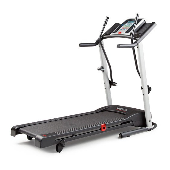
Model No. WLTL34913.0
Serial No.
Write the serial number in the space
above for future reference.
Serial Number
Decal
ACTIVATE YOUR
WARRANTY
To register your product and
activate your warranty today,
go to www.wesloservice.com/
registration.
CUSTOMER CARE
For service at any time, go to
www.wesloservice.com.
Or call 1-866-699-3756
Mon.––Fri. 6 a.m.––6 p.m. MT
Sat. 8 a.m.––12 p.m. MT
Please do not contact the store.
CAUTION
Read all precautions and instruc-
tions in this manual before using
this equipment. Save this manual
for future reference.
USER’'S MANUAL
Advertisement
Table of Contents

Related Manuals for Weslo Crosswalk G 3.2 Treadmill


Summary of Contents for Weslo Crosswalk G 3.2 Treadmill
- Page 1 Model No. WLTL34913.0 USER’’S MANUAL Serial No. Write the serial number in the space above for future reference. Serial Number Decal ACTIVATE YOUR WARRANTY To register your product and activate your warranty today, go to www.wesloservice.com/ registration. CUSTOMER CARE For service at any time, go to www.wesloservice.com.
-
Page 2: Table Of Contents
Apply the decal in the location shown. Note: The decal(s) may not be shown at actual size. WESLO is a registered trademark of ICON IP, Inc. -
Page 3: Important Precautions
4. The treadmill is intended for home use only. WESLO dealer, call the telephone number on Do not use the treadmill in any commercial, the front cover of this manual, or see your rental, or institutional setting. - Page 4 20. The heart rate monitor is not a medical 24. Never insert any object into any opening on device. Various factors, including the user’’s the treadmill. movement, may affect the accuracy of heart rate readings. The heart rate monitor is 25.
- Page 5 STANDARD SERVICE PLANS...
-
Page 6: Before You Begin
Thank you for selecting the new WESLO reading this manual, please see the front cover of this ® CROSSWALK G 3.2 treadmill. The CROSSWALK G manual. To help us assist you, note the product model 3.2 treadmill offers a selection of features designed number and serial number before contacting us. -
Page 7: Part Identification Chart
PART IDENTIFICATION CHART Use the drawings below to identify small parts used for assembly. The number in parentheses below each draw- ing is the key number of the part, from the PART LIST near the end of this manual. The number following the key number is the quantity used for assembly. -
Page 8: Assembly
ASSEMBLY •• To hire an authorized service technician •• Left parts are marked ““L”” or ““Left”” and right parts to assemble your exercise equipment, call are marked ““R”” or ““Right.”” 1-800-445-2480. •• To identify small parts, see page 7. •• Assembly requires two persons. ••... - Page 9 2. With the help of a second person, carefully tip the treadmill onto its side. Unfold the Frame (51) away from the Uprights (53, 54). Orient the Base (52) as shown. Attach the Base to the Left Upright (53) and the Right Upright (54) with four M10 x 58mm Bolts (2) and four M10 Nuts (73).
- Page 10 4. Set the Right Handrail (33) on the console assembly. Make sure that the console wire is Wire Tie not pinched. Remove the tie from the bracket Console Wire on the Right Handrail. If necessary, press the Cage Nut (102) back into place. Start an M5 x 16mm Screw (85) with an M5 Star Washer (7) into the Right Handrail, and Bracket...
- Page 11 6. Set the console assembly on the Uprights (53, 54). Make sure that no wires are pinched. Console Assembly Start four M8 x 15mm Bolts (8) with four M8 Star Washers (5) into the Uprights as shown. Do not tighten the Bolts yet. 7.
- Page 12 9. Attach the Left Upper Body Arm (105) to the Left Upright (53) with two 1/4" x 3 1/2" Screws (103), two 1/4" Flat Washers (101), and two M10 Star Washers (9). Make sure that the Left Upper Body Arm is on the side of the console assem- Console Assembly bly shown.
-
Page 13: Operation And Adjustment
OPERATION AND ADJUSTMENT HOW TO CONNECT THE POWER CORD nominal 120-volt circuit capable of carrying 15 or more amps. To avoid overloading the circuit, do Use a Surge Suppressor not plug other electrical devices, except for low- power devices such as cell phone chargers, into Your treadmill, like other electronic equipment, can be the surge suppressor or into an outlet on the same damaged by sudden voltage changes in your home’’s... - Page 14 CONSOLE DIAGRAM Clip FEATURES OF THE CONSOLE To turn on the power, see page 15. To use the man- ual mode, see page 15. To use a preset workout, The treadmill console offers a selection of features see page 17. designed to make your workouts more effective and enjoyable.
- Page 15 HOW TO TURN ON THE POWER the manual mode by pressing the Workout Select button repeatedly until only zeros appear in the IMPORTANT: If the treadmill has been exposed to displays. cold temperatures, allow it to warm to room tem- perature before you turn on the power.
- Page 16 The lower left dis- hold down the Stop button, insert the key into the play——As you exercise, console, and then release the Stop button. An M this display can show for metric kilometers or an E for English miles will the elapsed time and appear in the priority display.
- Page 17 HOW TO USE A PRESET WORKOUT for the next segment, the speed setting will flash in the display to alert you and the treadmill will 1. Insert the key into the console. automatically adjust to the new speed setting. The workout will continue in this way until the last seg- See HOW TO TURN ON THE POWER on page 15.
- Page 18 HOW TO CHANGE THE INCLINE OF THE TREADMILL HOW TO USE THE UPPER BODY ARMS To vary the intensity of your exercise, you can change As you walk on the treadmill, you can hold the hand- the incline of the treadmill. There are two incline levels. rails or use the upper body arms.
-
Page 19: How To Fold And Move The Treadmill
HOW TO FOLD AND MOVE THE TREADMILL HOW TO FOLD THE TREADMILL HOW TO MOVE THE TREADMILL Remove the key and unplug the power cord. Before moving the treadmill, fold it as described at the CAUTION: You must be able to safely lift 45 lbs. (20 left. -
Page 20: Troubleshooting
TROUBLESHOOTING Most treadmill problems can be solved by follow- b. Make sure that the power cord is plugged in. If the ing the simple steps below. Find the symptom that power cord is plugged in, unplug it, wait for five applies, and follow the steps listed. - Page 21 Locate the Reed Switch (89) and the Magnet (62) c. Your treadmill features a walking belt coated with on the left side of the Pulley (71). Turn the Pulley high-performance lubricant. IMPORTANT: Never until the Magnet is aligned with the Reed Switch. apply silicone spray or other substances to Make sure that the gap between the Magnet the walking belt or the walking platform unless...
- Page 22 b. If the walking belt slips when walked on, rst SYMPTOM: The upperbody arms squeak during remove the key and UNPLUG THE POWER CORD. Using the hex key, turn both idler roller screws clockwise, 1/4 of a turn. When the walk- a.
-
Page 23: Exercise Guidelines
EXERCISE GUIDELINES Burning Fat——To burn fat effectively, you must exer- WARNING: cise at a low intensity level for a sustained period of Before beginning this time. During the first few minutes of exercise, your or any exercise program, consult your physi- body uses carbohydrate calories for energy. - Page 24 SUGGESTED STRETCHES The correct form for several basic stretches is shown at the right. Move slowly as you stretch ——never bounce. 1. Toe Touch Stretch Stand with your knees bent slightly and slowly bend forward from your hips. Allow your back and shoulders to relax as you reach down toward your toes as far as possible.
- Page 25 NOTES...
-
Page 26: Part List
PART LIST Model No. WLTL34913.0 R0913A Key No. Qty. Description Key No. Qty. Description M10 x 110mm Bolt Frame M10 x 58mm Bolt Base M4.2 x 13mm Tek Screw Left Upright M4.2 x 16mm Screw Right Upright M8 Star Washer Idler Roller Warning Decal Motor Belt... - Page 27 Key No. Qty. Description Key No. Qty. Description 1/4" Flat Washer Left Upper Body Arm Cage Nut Right Upper Body Arm 1/4" x 3 1/2" Screw –– User’’s Manual #10 x 3/4" Screw Note: Specifications are subject to change without notice. For information about ordering replacement parts, see the back cover of this manual.
-
Page 28: Exploded Drawing
EXPLODED DRAWING A Model No. WLTL34913.0 R0913A... - Page 29 EXPLODED DRAWING B Model No. WLTL34913.0 R0913A...
- Page 30 EXPLODED DRAWING C Model No. WLTL34913.0 R0913A 43 43...
- Page 31 EXPLODED DRAWING D Model No. WLTL34913.0 R0913A...
-
Page 32: Ordering Replacement Parts
ORDERING REPLACEMENT PARTS To order replacement parts, please see the front cover of this manual. To help us assist you, be prepared to provide the following information when contacting us: •• the model number and serial number of the product (see the front cover of this manual) ••...