Honeywell CM900 Installation Manual
Cm927 / cm921 wireless programmable room thermostat & bdr91 relay box
Hide thumbs
Also See for CM900:
- Installation manual (13 pages) ,
- Installation manual (2 pages) ,
- Installation manual
Table of Contents
Advertisement
CM900 Wireless
Installation Guide
CM927 / CM921 Wireless Programmable
Room Thermostat & BDR91 Relay Box
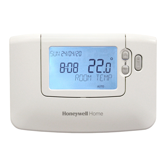
Description
The Honeywell CM900 Wireless (CM927 or
CM921) is a modern wireless programmable
room thermostat based on Honeywell's proven
programming philosophy. To further improve the
ease of use, this product includes an extra large
LCD display with backlighting and LoT Technology
to assist customers during daily use.
The CM927/921 room thermostat communicates
with the BDR91 Relay Box on an 868MHz Radio
Frequency (RF) band to control a single heating
system component such as a boiler, pump or
zone valve. Neither product will communicate with
other RF products that use different frequencies or
communication protocols.
Note: The RF link between the individual room
thermostat (CM927/921) and Relay Box (BDR91)
in system packs provided by Honeywell is pre-
configured at the factory and therefore SHOULD
be installed at the same site. This makes the
installation process fast and easy, but if products
from individual system packs are separated, or
mixed with other pre-configured system packs
during installations please refer to section 5.1
Binding / Rebinding Procedure to bind the desired
units together and allow them to communicate with
each other.
Table of Contents
Section
1) Installation Information ................................. 2
2) Installing the CM900 Wireless System ......... 3
............................................... 4
................................................ 5
3) Basic Operation of the System ..................... 6
....................................... 6
4) Installer Mode ................................................. 6
5) Additional Installation Information ............. 11
........................................ 11
6) Trouble Shooting .......................................... 12
........................................ 12
Page
................................... 3
........................ 4
........................ 4
................. 5
............................. 6
...................................... 6
................................... 7
............ 7
.. 8
.. 8
............................... 9
..... 9
.................. 10
...................... 11
................................ 11
................................. 12
50039987-003 A
Advertisement
Table of Contents

Related Manuals for Honeywell CM900


Summary of Contents for Honeywell CM900
-
Page 1: Table Of Contents
1) Installation Information ......... 2 room thermostat based on Honeywell’s proven programming philosophy. To further improve the 2) Installing the CM900 Wireless System ..3 ease of use, this product includes an extra large ........3 LCD display with backlighting and LoT Technology 2.1 Installing the Relay Box... -
Page 2: Installation Information
2.2.3 Locating the Room Thermostat. If the position is unsuitable the Relay Box will not respond and an alternative position must be selected. = Signal Strength Wall Wall Wall Ceiling Max. Signal Length 30 metres Typical example of Building Fabric Signal losses CM900 Wireless - Programmable Room Thermostat... -
Page 3: Installing The Cm900 Wireless System
2) Installing the CM900 Wireless System Please follow the illustrations and information below in sequence to install the Relay Box and room thermostat correctly. For applications other than gas boilers, enabling special features and to see what other system options are available refer to section 4) Installer Mode. -
Page 4: Installing The Room Thermostat
NOTE: If the green LED is not switched at specified intervals, the red LED is flashing or if you are installing a replacement Relay Box or room thermostat, follow the procedures described in section 5.1 Binding / Rebinding Procedure. CM900 Wireless - Programmable Room Thermostat... -
Page 5: Locating The Room Thermostat
2.2.3 Locating the Room Thermostat While still in the Test Mode, as described in section 2.2.2, the room thermostat should be located taking the following into consideration and reviewing the illustrations below: 1. Find a suitable location where the signal transmission is reliable. Reliable transmission is indicated when the Relay Box is flashing the green LED every 6 seconds. -
Page 6: Basic Operation Of The System
Parameters are divided into two groups: - Category 1 parameters – Room Thermostat Setup - Category 2 parameters – System Setup. These are all listed in section 4.5 Installer Parameters Table. CM900 Wireless - Programmable Room Thermostat... -
Page 7: Entering Installer Mode
4.1 Entering Installer Mode COPY DATE PROG AUTO CM927 1..6 The unit will display the first parameter of installer Move the slider switch to the OFF mode. parameter group category 1 (from Parameter n.1 Press and hold the button and the two &... -
Page 8: Using The Room Thermostat For Specific Applications
The normal lower limit of 5°C can be 1) to the desired upper limit. increased up to 21°C to protect inhabitants from cold. Set parameter 7:LL (category 1) to the desired lower limit. CM900 Wireless - Programmable Room Thermostat... -
Page 9: Installer Parameters Table
4.5 Installer Parameters Table 4.5.1 Category 1 - Room Thermostat Settings Parameter Parameter Factory Default Setting Optional Setting Category 1 Parameters – Room Thermostat Settings Display Description Display Description AM-PM / 24hr 1:CL 24 hr clock display 12 hr – AM/PM clock display format Display format Reset Time/ Temp... -
Page 10: Category 2 - System Settings
Relay 20% on / 80% off Communications Instruction The following Parameters are for the control of other Honeywell Wireless products such as Wireless Underfloor Heating controls and Wireless Radiator controls. For more information please contact Honeywell sales. Room Temperature 8:Su... -
Page 11: Additional Installation Information
Relay Box. The red LED is switched off to confirm successful binding operation. If the red LED still flashes push the button again until binding is successful. 6. Now go to Section 2) Installing the CM900 Wireless System to setup the system. 5.2 Multi-Zone System... -
Page 12: Trouble Shooting
Directive 1999/5/EC, 2006/95/EC and 2004/108/EC. Manufactured for and on behalf of the Environmental and Combustion Controls Division of Honeywell Technologies Sàrl, ACS-ECC EMEA, Z.A. La Pièce 16, 1180 Rolle, Switzerland by its Authorised Representative Honeywell International Inc.