HP ProCurve Switch 6120G/XG Manual
Hp procurve series 6120 blade switches access security guide
Hide thumbs
Also See for ProCurve Switch 6120G/XG:
- Configuration manual (662 pages) ,
- Manual (606 pages) ,
- Management manual (222 pages)
Table of Contents
Advertisement
Advertisement
Table of Contents

Related Manuals for HP ProCurve Switch 6120G/XG


Summary of Contents for HP ProCurve Switch 6120G/XG
- Page 1 ProCurve Series 6120 Switches Access Security Guide August 2009...
- Page 2 ANY KIND WITH REGARD TO THIS MATERIAL, INCLUDING, BUT NOT LIMITED TO, THE IMPLIED WARRANTIES OF Applicable Products MERCHANTABILITY AND FITNESS FOR A PARTICULAR PURPOSE. Hewlett-Packard shall not be liable for errors HP ProCurve Switch 6120G/XG (498358-B21) contained herein or for incidental or consequential damages in...
-
Page 4: Table Of Contents
Contents Product Documentation About Your Switch Manual Set ......xvii Printed Publications......... xvii Electronic Publications . - Page 5 2 Configuring Username and Password Security Contents ............2-1 Overview .
- Page 6 Password Recovery Process ....... . . 2-34 3 Web and MAC Authentication Contents .
- Page 7 Client Status ..........3-60 4 TACACS+ Authentication Contents .
- Page 8 Authentication Services ........5-3 Accounting Services .
- Page 9 2. Configure Accounting Types and the Controls for Sending Reports to the RADIUS Server ....5-42 3. (Optional) Configure Session Blocking and Interim Updating Options .
- Page 10 7 Configuring Secure Socket Layer (SSL) Contents ............7-1 Overview .
- Page 11 Using DHCP Snooping with Option 82 ......8-9 Changing the Remote-id from a MAC to an IP Address ..8-11 Disabling the MAC Address Check .
- Page 12 9 Traffic/Security Filters and Monitors Contents ............9-1 Overview .
- Page 13 Terminology ..........10-6 General 802.1X Authenticator Operation .
- Page 14 Port-Security ..........10-46 Configuring Switch Ports To Operate As Supplicants for 802.1X Connections to Other Switches .
- Page 15 Deploying MAC Lockdown ....... . . 11-26 MAC Lockout ..........11-26 Port Security and MAC Lockout .
- Page 16 Building IP Masks ......... . . 12-10 Configuring One Station Per Authorized Manager IP Entry .
-
Page 18: Product Documentation
Product Documentation About Your Switch Manual Set N o t e For the latest version of switch documentation, please visit any of the follow- ing websites: www.procurve.com/manuals www.hp.com/go/bladesystem/documentation h18004.www1.hp.com/products/blades/components/c-class-tech-installing.html Printed Publications The publication listed below is printed and shipped with your switch. The latest version is also available in PDF format, as described in the Note at the top of this page. -
Page 19: Software Feature Index
Software Feature Index This feature index indicates which manual to consult for information on a given software feature. N o t e This Index does not cover IPv6 capable software features. For information on IPv6 protocol operations and features (such as DHCPv6, DNS for IPv6, and Ping6), refer to the IPv6 Configuration Guide. - Page 20 Intelligent Edge Software Manual Features Management Advanced Multicast and Access Traffic Routing Security Configuration Management Guide Downloading Software Event Log Factory Default Settings Flow Control (802.3x) File Transfers Friendly Port Names GVRP Identity-Driven Management (IDM) IGMP Interface Access (Telnet, Console/Serial, Web) IP Addressing Jumbo Packets LACP...
- Page 21 Intelligent Edge Software Manual Features Management Advanced Multicast and Access Traffic Routing Security Configuration Management Guide Port Monitoring Port Security Port Status Port Trunking (LACP) Port-Based Access Control (802.1X) Protocol VLANS Quality of Service (QoS) RADIUS Authentication and Accounting RADIUS-Based Configuration RMON 1,2,3,9 Secure Copy SFTP...
- Page 22 Intelligent Edge Software Manual Features Management Advanced Multicast and Access Traffic Routing Security Configuration Management Guide VLANs Web Authentication RADIUS Support Web-based Authentication Web UI...
-
Page 23: Security Overview
Security Overview Contents Security Overview Contents Introduction ..........1-2 About This Guide . -
Page 24: Introduction
Security Overview Introduction Introduction This chapter provides an overview of the security features included on your switch. Table 1-1 on page 1-3 outlines the access security and authentication features, while Table 1-2 on page 1-7 highlights the additional features designed to help secure and protect your network. For detailed information on individual features, see the references provided. -
Page 25: Access Security Features
Security Overview Access Security Features Access Security Features This section provides an overview of the switch’s access security features, authentication protocols, and methods. Table 1-1 lists these features and provides summary configuration guidelines. For more in-depth information, see the references provided (all chapter and page references are to this Access Security Guide unless a different manual name is indicated). - Page 26 Security Overview Access Security Features Feature Default Security Guidelines More Information and Setting Configuration Details Telnet and enabled The default remote management protocols enabled on “Quick Start: Using the Web-browser the switch are plain text protocols, which transfer Management Interface access passwords in open or plain text that is easily captured.
- Page 27 Security Overview Access Security Features Feature Default Security Guidelines More Information and Setting Configuration Details disabled Secure Socket Layer (SSL) and Transport Layer Security “Quick Start: Using the (TLS) provide remote Web browser access to the switch Management Interface via authenticated transactions and encrypted paths Wizard”...
- Page 28 Security Overview Access Security Features Feature Default Security Guidelines More Information and Setting Configuration Details 802.1X Access none This feature provides port-based or user-based Chapter 13 “Configuring Control authentication through a RADIUS server to protect the Port-Based and User-Based switch from unauthorized access and to enable the use Access Control (802.1X)”...
-
Page 29: Network Security Features
Security Overview Network Security Features Network Security Features This section outlines features and defence mechanisms for protecting access through the switch to the network. For more detailed information, see the indicated chapters. Table 1-2. Network Security—Default Settings and Security Guidelines Feature Default Security Guidelines... - Page 30 Security Overview Network Security Features Feature Default Security Guidelines More Information and Setting Configuration Details Connection- none This feature helps protect the network from attack and Chapter 3, “Virus Throttling Rate Filtering is recommended for use on the network edge. It is (Connection-Rate Filtering)”...
-
Page 31: Getting Started With Access Security
Security Overview Getting Started with Access Security Getting Started with Access Security ProCurve switches are designed as “plug and play” devices, allowing quick and easy installation in your network. In its default configuration the switch is open to unauthorized access of various types. When preparing the switch for network operation, therefore, ProCurve strongly recommends that you enforce a security policy to help ensure that the ease in getting started is not used by unauthorized persons as an opportunity for access and possible... -
Page 32: Quick Start: Using The Management Interface Wizard
Security Overview Getting Started with Access Security Keeping the switch in a locked wiring closet or other secure space helps to prevent unauthorized physical access. As additional precautions, you can do the following: Disable or re-enable the password-clearing function of the Clear button. ■... - Page 33 Security Overview Getting Started with Access Security The welcome banner appears and the first setup option is displayed (Operator password). As you advance through the wizard, each setup option displays the current value in brackets [ ] as shown in Figure 1-1. Welcome to the Management Interface Setup Wizard This wizard will help you with the initial setup of the various management interfaces.
-
Page 34: Web: Management Interface Wizard
Security Overview Getting Started with Access Security When you enter the wizard, you have the following options: • To update a setting, type in a new value, or press [Enter] to keep the current value. • To quit the wizard without saving any changes, press [CTRL-C] at any time. - Page 35 Security Overview Getting Started with Access Security The Welcome window appears. Figure 1-2. Management Interface Wizard: Welcome Window This page allows you to choose between two setup types: Typical—provides a multiple page, step-by-step method to configure • security settings, with on-screen instructions for each option. •...
- Page 36 Security Overview Getting Started with Access Security The summary setup screen displays the current configuration settings for all setup options (see Figure 1-3). Figure 1-3. Management Interface Wizard: Summary Setup From this screen, you have the following options: • To change any setting that is shown, type in a new value or make a different selection.
-
Page 37: Snmp Security Guidelines
Security Overview Getting Started with Access Security SNMP Security Guidelines In the default configuration, the switch is open to access by management stations running SNMP (Simple Network Management Protocol) management applications capable of viewing and changing the settings and status data in the switch’s MIB (Management Information Base). - Page 38 Security Overview Getting Started with Access Security If SNMP access to the hpSwitchAuth MIB is considered a security risk in your network, then you should implement the following security precautions when downloading and booting from the software: ■ If SNMP access to the authentication configuration (hpSwitchAuth) MIB described above is not desirable for your network, then immediately after downloading and booting from the software for the first time, use the following command to disable this feature:...
-
Page 39: Precedence Of Security Options
Security Overview Precedence of Security Options Precedence of Security Options This section explains how port-based security options, and client-based attributes used for authentication, get prioritized on the switch. Precedence of Port-Based Security Options Where the switch is running multiple security options, it implements network traffic security based on the OSI (Open Systems Interconnection model) precedence of the individual options, from the lowest to the highest. -
Page 40: Network Immunity Manager
Security Overview Precedence of Security Options value applied to a client session is determined in the following order (from highest to lowest priority) in which a value configured with a higher priority overrides a value configured with a lower priority: Attribute profiles applied through the Network Immunity network-man- agement application using SNMP (see “Network Immunity Manager”) 802.1X authentication parameters (RADIUS-assigned) -
Page 41: Arbitrating Client-Specific Attributes
Security Overview Precedence of Security Options The profile of attributes applied for each client (MAC address) session is stored in the hpicfUsrProfile MIB, which serves as the configuration interface for Network Immunity Manager. A client profile consists of NIM-configured, RADIUS-assigned, and statically configured parameters. Using show commands for 802.1X, web or MAC authentication, you can verify which RADIUS -assigned and statically configured parameters are supported and if they are supported on a per-port or per-client basis. - Page 42 Security Overview Precedence of Security Options Client-specific configurations are applied on a per-parameter basis on a port. In a client-specific profile, if DCA detects that a parameter has configured values from two or more levels in the hierarchy of precedence described above, DCA decides which parameters to add or remove, or whether to fail the authentication attempt due to an inability to apply the parameters.
-
Page 43: Procurve Identity-Driven Manager (Idm)
Security Overview ProCurve Identity-Driven Manager (IDM) ProCurve Identity-Driven Manager (IDM) IDM is a plug-in to ProCurve Manager Plus (PCM+) and uses RADIUS-based technologies to create a user-centric approach to network access management and network activity tracking and monitoring. IDM enables control of access security policy from a central management server, with policy enforcement to the network edge, and protection against both external and internal threats. -
Page 44: Configuring Username And Password Security
Configuring Username and Password Security Contents Overview ........... . . 2-3 Configuring Local Password Security . - Page 45 Configuring Username and Password Security Contents Re-Enabling the Clear Button and Setting or Changing the “Reset-On-Clear” Operation ....2-30 Changing the Operation of the Reset+Clear Combination ..2-31 Password Recovery .
-
Page 46: Overview
Configuring Username and Password Security Overview Overview Feature Default Menu Set Usernames none — — page 2-9 Set a Password none page page 2-8 page 2-9 Delete Password Protection page page 2-8 page 2-9 show front-panel-security — page 1-13 — front-panel-security —... - Page 47 Configuring Username and Password Security Overview Level Actions Permitted Manager: Access to all console interface areas. This is the default level. That is, if a Manager password has not been set prior to starting the current console session, then anyone having access to the console can access any area of the console interface.
- Page 48 Configuring Username and Password Security Overview N o t e s The manager and operator passwords and (optional) usernames control access to the menu interface, CLI, and web browser interface. If you configure only a Manager password (with no Operator password), and in a later session the Manager password is not entered correctly in response to a prompt from the switch, then the switch does not allow management access for that session.
-
Page 49: Configuring Local Password Security
Configuring Username and Password Security Configuring Local Password Security Configuring Local Password Security Menu: Setting Passwords As noted earlier in this section, usernames are optional. Configuring a user- name requires either the CLI or the web browser interface. From the Main Menu select: 3. - Page 50 Configuring Username and Password Security Configuring Local Password Security To Delete Password Protection (Including Recovery from a Lost Password): This procedure deletes all usernames (if configured) and pass- words (Manager and Operator). If you have physical access to the switch, press and hold the Clear button (on the front of the switch) for a minimum of one second to clear all password protection, then enter new passwords as described earlier in this chapter.
-
Page 51: Cli: Setting Passwords And Usernames
Configuring Username and Password Security Configuring Local Password Security CLI: Setting Passwords and Usernames Commands Used in This Section password See below. Configuring Manager and Operator Passwords. N o t e You can configure manager and operator passwords in one step. See “Saving Security Credentials in a Config File”... -
Page 52: Web: Setting Passwords And Usernames
Configuring Username and Password Security Configuring Local Password Security If you want to remove both operator and manager password protection, use the no password all command. Web: Setting Passwords and Usernames In the web browser interface you can enter passwords and (optional) user- names. -
Page 53: Saving Security Credentials In A Config File
Configuring Username and Password Security Saving Security Credentials in a Config File Saving Security Credentials in a Config File You can store and view the following security settings in internal flash memory by entering the include-credentials command: ■ Local manager and operator passwords and (optional) user names that control access to a management session on the switch through the CLI, menu interface, or web browser interface SNMP security credentials used by network management stations to... -
Page 54: Enabling The Storage And Display Of Security Credentials
Configuring Username and Password Security Saving Security Credentials in a Config File The chapter on “Switch Memory and Configuration” in the Management ■ and Configuration Guide. ■ “Configuring Local Password Security” on page 2-6 in this guide. Enabling the Storage and Display of Security Credentials To enable the security settings, enter the include-credentials command. -
Page 55: Local Manager And Operator Passwords
Configuring Username and Password Security Saving Security Credentials in a Config File Local Manager and Operator Passwords The information saved to the running-config file when the include-credentials command is entered includes: password manager [user-name <name>] <hash-type> <pass-hash> password operator [user-name <name>] <hash-type> <pass-hash> where <name>... -
Page 56: Snmp Security Credentials
Configuring Username and Password Security Saving Security Credentials in a Config File user-name <name>: the optional text string of the user name associated with the password. <hash-type>: specifies the type of algorithm (if any) used to hash the password. Valid values are plaintext or sha-1 <password>: the clear ASCII text string or SHA-1 hash of the password. -
Page 57: 802.1X Port-Access Credentials
Configuring Username and Password Security Saving Security Credentials in a Config File [priv <priv-pass>] is the (optional) hashed privacy password used by a privacy protocol to encrypt SNMPv3 messages between the switch and the station. The following example shows the additional security credentials for SNMPv3 users that can be saved in a running-config file: snmpv3 user boris \ auth md5 “9e4cfef901f21cf9d21079debeca453”... -
Page 58: Tacacs+ Encryption Key Authentication
Configuring Username and Password Security Saving Security Credentials in a Config File The password port-access values are configured separately from the manager and operator passwords configured with the password manager and password operator commands and used for management access to the switch. For information on the new password command syntax, see “Password Command Options”... -
Page 59: Ssh Client Public-Key Authentication
Configuring Username and Password Security Saving Security Credentials in a Config File during authentication sessions. Both the switch and the server have a copy of the key; the key is never transmitted across the network. For more information, refer to “3. Configure the Switch To Access a RADIUS Server” on page 6-14 in this guide. - Page 60 Configuring Username and Password Security Saving Security Credentials in a Config File “keystring”: a legal SSHv2 (RSA or DSA) public key. The text string for the public key must be a single quoted token. If the keystring contains double-quotes, it can be quoted with single quotes ('keystring').
- Page 61 Configuring Username and Password Security Saving Security Credentials in a Config File To display the SSH public-key configurations (72 characters per line) stored in a configuration file, enter the show config or show running-config command. The following example shows the SSH public keys configured for manager access, along with the hashed content of each SSH client public-key, that are stored in a configuration file: include-credentials...
-
Page 62: Operating Notes
Configuring Username and Password Security Saving Security Credentials in a Config File Operating Notes C a u t i o n When you first enter the include-credentials command to save the ■ additional security credentials to the running configuration, these settings are moved from internal storage on the switch to the running-config file. - Page 63 Configuring Username and Password Security Saving Security Credentials in a Config File • copy config <source-filename> config <target-filename>: Makes a local copy of an existing startup-config file by copying the contents of the startup-config file in one memory slot to a new startup-config file in another, empty memory slot.
-
Page 64: Restrictions
Configuring Username and Password Security Saving Security Credentials in a Config File Restrictions The following restrictions apply when you enable security credentials to be stored in the running configuration with the include-credentials command: ■ The private keys of an SSH host cannot be stored in the running configuration. - Page 65 Configuring Username and Password Security Saving Security Credentials in a Config File the username and password used as 802.1X authentication credentials for access to the switch. You can store the password port-access values in the running configuration file by using the include-credentials command. Note that the password port-access values are configured separately from local operator username and passwords configured with the password operator command and used for management access to the switch.
-
Page 66: Front-Panel Security
Configuring Username and Password Security Front-Panel Security Front-Panel Security The front-panel security features provide the ability to independently enable or disable some of the functions of the two buttons located on the front of the switch for clearing the password (Clear button) or restoring the switch to its factory default configuration (Reset+Clear buttons together). -
Page 67: Front-Panel Button Functions
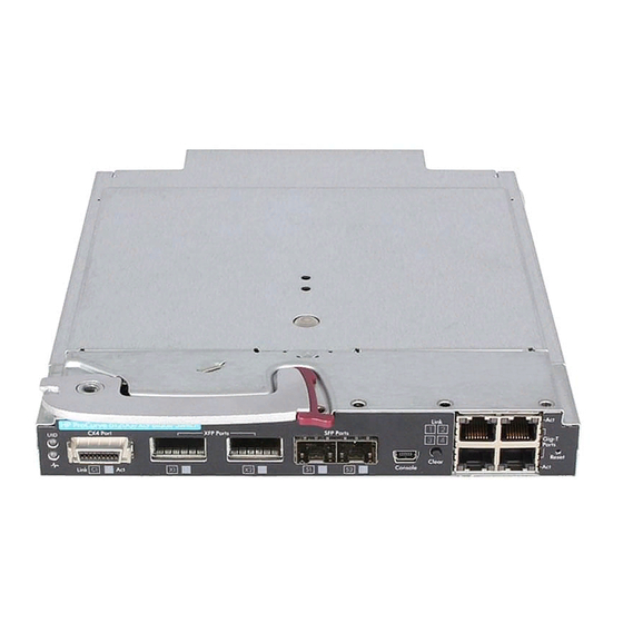
This section describes the functionality of the Clear and Reset buttons located on the front panel of the switch. Reset Button Clear Button Figure 2-6. Front-Panel Button Locations on a ProCurve 6120G/XG Switch Clear Button Reset Button Figure 2-7. Front-Panel Button Locations on a ProCurve 6120XG Switch... -
Page 68: Clear Button
Configuring Username and Password Security Front-Panel Security Clear Button Pressing the Clear button alone for five seconds resets the password(s) configured on the switch. Reset Clear Figure 2-8. Press the Clear Button for Five Seconds To Reset the Password(s) Reset Button Pressing the Reset button alone for one second causes the switch to reboot. - Page 69 Configuring Username and Password Security Front-Panel Security While holding the Reset button, press and hold the Clear button for five seconds. Clear Reset Release the Reset button. Clear Reset If the Clear button is held for greater then 2.5 seconds, configuration will be cleared, and the switch will reboot.
-
Page 70: Configuring Front-Panel Security
Configuring Username and Password Security Front-Panel Security Configuring Front-Panel Security Using the front-panel-security command from the global configuration context in the CLI you can: • Disable or re-enable the password-clearing function of the Clear button. Disabling the Clear button means that pressing it does not remove local password protection from the switch. - Page 71 Configuring Username and Password Security Front-Panel Security Reset-on-clear: Shows the status of the reset-on-clear option (Enabled or Disabled). When reset-on-clear is disabled and Clear Password is enabled, then pressing the Clear button erases the local usernames and passwords from the switch. When reset-on-clear is enabled, pressing the Clear button erases the local usernames and passwords from the switch and reboots the switch.
-
Page 72: Disabling The Clear Password Function Of The Clear Button
Configuring Username and Password Security Front-Panel Security Disabling the Clear Password Function of the Clear Button Syntax: no front-panel-security password-clear In the factory-default configuration, pressing the Clear button on the switch’s front panel erases any local usernames and passwords configured on the switch. This command disables the password clear function of the Clear button, so that pressing it has no effect on any local usernames and passwords. -
Page 73: Re-Enabling The Clear Button And Setting Or Changing The "Reset-On-Clear" Operation
Configuring Username and Password Security Front-Panel Security Re-Enabling the Clear Button and Setting or Changing the “Reset-On-Clear” Operation Syntax: [no] front-panel-security password-clear reset-on-clear This command does both of the following: • Re-enables the password-clearing function of the Clear button on the switch’s front panel. •... -
Page 74: Changing The Operation Of The Reset+Clear Combination
Configuring Username and Password Security Front-Panel Security Shows password-clear disabled. Enables password-clear, with reset-on- clear disabled by the “no” statement at the beginning of the command. Shows password-clear enabled, with reset-on-clear disabled. Figure 2-12. Example of Re-Enabling the Clear Button’s Default Operation Changing the Operation of the Reset+Clear Combination In their default configuration, using the Reset+Clear buttons in the combina- tion described under “Restoring the Factory Default Configuration”... -
Page 75: Password Recovery
Configuring Username and Password Security Password Recovery The command to disable the factory-reset operation produces this caution. To complete the command, press [Y]. To abort the command, press [N]. Completes the command to disable the factory reset option. Displays the current front- panel-security configuration, with Factory Reset disabled. - Page 76 Configuring Username and Password Security Password Recovery factory-default configuration. This can disrupt network operation and make it necessary to temporarily disconnect the switch from the network to prevent unauthorized access and other problems while it is being reconfigured. Also, with factory-reset enabled, unauthorized users can use the Reset+Clear button combination to reset the switch to factory-default configuration and gain management access to the switch.
-
Page 77: Password Recovery Process
Configuring Username and Password Security Password Recovery Figure 2-14. Example of the Steps for Disabling Password-Recovery Password Recovery Process If you have lost the switch’s manager username/password, but password- recovery is enabled, then you can use the Password Recovery Process to gain management access to the switch with an alternate password supplied by ProCurve. -
Page 78: Web And Mac Authentication
Web and MAC Authentication Contents Overview ........... . . 3-3 Web Authentication . - Page 79 Web and MAC Authentication Contents Overview ..........3-50 Configuration Commands for MAC Authentication .
-
Page 80: Overview
Web and MAC Authentication Overview Overview Feature Default Menu Configure Web Authentication — 3-20 — Configure MAC Authentication — 3-50 — Display Web Authentication Status and Configuration — 3-28 — Display MAC Authentication Status and Configuration — 3-54 — Web and MAC authentication are designed for employment on the “edge” of a network to provide port-based security measures for protecting private networks and a switch from unauthorized access. -
Page 81: Mac Authentication
Web and MAC Authentication Overview Note A proxy server is not supported for use by a browser on a client device that accesses the network through a port configured for web authentication. In the login page, a client enters a username and password, which the ■... -
Page 82: Authorized And Unauthorized Client Vlans
Web and MAC Authentication Overview Each new Web/MAC Auth client always initiates a MAC authentica- ■ tion attempt. This same client can also initiate Web authentication at any time before the MAC authentication succeeds. If either authenti- cation succeeds then the other authentication (if in progress) is ended. -
Page 83: Radius-Based Authentication
Web and MAC Authentication How Web and MAC Authentication Operate clients by using an “unauthorized” VLAN for each session. The unauthorized VLAN ID assignment can be the same for all ports, or different, depending on the services and access you plan to allow for unauthenticated clients. You configure access to an optional, unauthorized VLAN when you configure Web and MAC authentication on a port. -
Page 84: Web-Based Authentication
Web and MAC Authentication How Web and MAC Authentication Operate Web-based Authentication When a client connects to a Web-Auth enabled port, communication is redi- rected to the switch. A temporary IP address is assigned by the switch and a login screen is presented for the client to enter their username and password. The default User Login screen is shown in Figure 3-1. - Page 85 Web and MAC Authentication How Web and MAC Authentication Operate If the client is authenticated and the maximum number of clients allowed on the port (client-limit) has not been reached, the port is assigned to a static, untagged VLAN for network access. After a successful login, a client may be redirected to a URL if you specify a URL value (redirect-url) when you configure web authentication.
-
Page 86: Mac-Based Authentication
Web and MAC Authentication How Web and MAC Authentication Operate A client may not be authenticated due to invalid credentials or a RADIUS server timeout. The max-retries parameter specifies how many times a client may enter their credentials before authentication fails. The server-timeout parameter sets how long the switch waits to receive a response from the RADIUS server before timing out. - Page 87 Web and MAC Authentication How Web and MAC Authentication Operate The assigned port VLAN remains in place until the session ends. Clients may be forced to reauthenticate after a fixed period of time (reauth-period) or at any time during a session (reauthenticate). An implicit logoff period can be set if there is no activity from the client after a given amount of time (logoff-period).
-
Page 88: Terminology
Web and MAC Authentication Terminology Terminology Authorized-Client VLAN: Like the Unauthorized-Client VLAN, this is a conventional, static, untagged, port-based VLAN previously configured on the switch by the System Administrator. The intent in using this VLAN is to provide authenticated clients with network access and services. When the client connection terminates, the port drops its membership in this VLAN. -
Page 89: Operating Rules And Notes
Web and MAC Authentication Operating Rules and Notes Operating Rules and Notes ■ The switch supports concurrent 802.1X , Web and MAC authentication operation on a port (with up to 2 clients allowed). However, concur- rent operation of Web and MAC authentication with other types of authentication on the same port is not supported. - Page 90 Web and MAC Authentication Operating Rules and Notes If there is a RADIUS-assigned VLAN, then, for the duration of the client session, the port belongs to this VLAN and temporarily drops all other VLAN memberships. If there is no RADIUS-assigned VLAN, then, for the duration of the client session, the port belongs to the Authorized VLAN (if configured) and temporarily drops all other VLAN memberships.
-
Page 91: Setup Procedure For Web/Mac Authentication
Web and MAC Authentication Setup Procedure for Web/MAC Authentication We b / M A C Web or MAC authentication and LACP are not supported at the same time on A u t h e n t i c a t i on a port. - Page 92 Web and MAC Authentication Setup Procedure for Web/MAC Authentication ProCurve (config)# show port-access config Port Access Status Summary Port-access authenticator activated [No] : Yes Allow RADIUS-assigned dynamic (GVRP) VLANs [No] : Yes Supplicant Authenticator Web Auth Mac Auth Port Enabled Enabled Enabled Enabled...
-
Page 93: Configuring The Radius Server To Support Mac Authentication
Web and MAC Authentication Setup Procedure for Web/MAC Authentication Note that when configuring a RADIUS server to assign a VLAN, you can use either the VLAN’s name or VID. For example, if a VLAN configured in the switch has a VID of 100 and is named vlan100, you could configure the RADIUS server to use either “100”... -
Page 94: Configuring The Switch To Access A Radius Server
Web and MAC Authentication Setup Procedure for Web/MAC Authentication aa-bb-cc-dd-ee-ff aa:bb:cc:dd:ee:ff AABBCCDDEEFF AABBCC-DDEEFF AA-BB-CC-DD-EE-FF AA:BB:CC:DD:EE:FF ■ If the device is a switch or other VLAN-capable device, use the base MAC address assigned to the device, and not the MAC address assigned to the VLAN through which the device communicates with the authenticator switch. - Page 95 Web and MAC Authentication Setup Procedure for Web/MAC Authentication Syntax: [no] radius-server [host < ip-address >] [oobm] Adds a server to the RADIUS configuration or (with no) deletes a server from the configuration. You can config- ure up to three RADIUS server addresses. The switch uses the first server it successfully accesses.
- Page 96 Web and MAC Authentication Setup Procedure for Web/MAC Authentication For example, to configure the switch to access a RADIUS server at IP address 192.168.32.11 using a server specific shared secret key of ‘1A7rd’ Figure 3-5. Example of Configuring a Switch To Access a RADIUS Server 3-19...
-
Page 97: Configuring Web Authentication
Web and MAC Authentication Configuring Web Authentication Configuring Web Authentication Overview If you have not already done so, configure a local username and password pair on the switch. Identify or create a redirect URL for use by authenticated clients. Pro- Curve recommends that you provide a redirect URL when using Web Authentication. -
Page 98: Configuration Commands For Web Authentication
Web and MAC Authentication Configuring Web Authentication • You can block only incoming traffic on a port before authentication occurs. Outgoing traffic with unknown destination addresses is flooded on unauthenticated ports configured for web authentication. For example, Wake-on-LAN traffic is transmitted on a web-authenti- cated egress port that has not yet transitioned to the authenticated state;... - Page 99 Web and MAC Authentication Configuring Web Authentication Syntax: aaa port-access <port-list > controlled-directions <both | in> After you enable web-based authentication on specified ports, you can use the aaa port-access controlled-direc- tions command to configure how a port transmits traffic before it successfully authenticates a client and enters the authenticated state.
- Page 100 Web and MAC Authentication Configuring Web Authentication Syntax: aaa port-access <port-list > controlled-directions <both | in> — Continued — Notes: ■ For information on how to configure the prerequisites for using the aaa port-access controlled-directions in command, see Chapter 4, “Multiple Instance Spanning-Tree Operation”...
- Page 101 Web and MAC Authentication Configuring Web Authentication Syntax: [no] aaa port-access web-based <port-list> Enables web-based authentication on the specified ports. Use the no form of the command to disable web- based authentication on the specified ports. Syntax: aaa port-access web-based <port-list> [auth-vid <vid>]] no aaa port-access web-based <port-list>...
- Page 102 Web and MAC Authentication Configuring Web Authentication Specifies the base address/mask for the temporary IP pool used by DHCP. The base address can be any valid ip address (not a multicast address). Valid mask range value is <255.255.240.0 - 255.255.255.0>. (Default: 192.168.0.0/255.255.255.0) Syntax: aaa port-access web-based [dhcp-lease <5 - 25>]...
- Page 103 Web and MAC Authentication Configuring Web Authentication ProCurve Switch (config)# no aaa port-access web-based 47 ewa-server 10.0.12.181 ProCurve Switch (config)# Figure 7. Removing a Web Server with the aaa port-access web-based ews- server Command aaa port-access web-based <port-list > logoff-period <60-9999999>...
- Page 104 Web and MAC Authentication Configuring Web Authentication Syntax: aaa port-access web-based <port-list > [reauth-period <0 - 9999999>] Specifies the time period, in seconds, the switch enforces on a client to re-authenticate. When set to 0, reauthentication is disabled. (Default: 300 seconds) Syntax: aaa port-access web-based <port-list>...
-
Page 105: Show Commands For Web Authentication
Web and MAC Authentication Configuring Web Authentication Show Commands for Web Authentication Command Page show port-access web-based [port-list] 3-28 show port-access web-based clients [port-list] 3-29 show port-access web-based clients <port-list> detailed 3-30 show port-access web-based config [port-list] 3-31 show port-access web-based config <port-list> detailed 3-32 show port-access web-based config [port-list] auth-server 3-33... - Page 106 Web and MAC Authentication Configuring Web Authentication ProCurve (config)# show port-access web-based Port Access Web-Based Status Auth Unauth Untagged Tagged Port Cntrl Port Clients Clients VLAN VLANs ----- -------- -------- -------- ------ -------- ------ 4006 70000000 MACbased No Figure 4. Example of show port-access web-based Command Output Syntax: show port-access web-based clients [port-list]...
- Page 107 Web and MAC Authentication Configuring Web Authentication Syntax: show port-access web-based clients <port-list> detailed Displays detailed information on the status of web- authenticated client sessions on specified switch ports. ProCurve (config)# show port-access web-based clients 1 detailed Port Access Web-Based Client Status Detailed Client Base Details : Port Session Status : authenticated...
- Page 108 Web and MAC Authentication Configuring Web Authentication Syntax: show port-access web-based config [port-list] Displays the currently configured Web Authentication settings for all switch ports or specified ports, including: • Temporary DHCP base address and mask • Support for RADIUS-assigned dynamic VLANs (Yes or •...
- Page 109 Web and MAC Authentication Configuring Web Authentication Syntax: show port-access web-based config <port-list> detailed Displays more detailed information on the currently config- ured Web Authentication settings for specified ports. ProCurve (config)# show port-access web-based config 1 detailed Port Access Web-Based Detailed Configuration Port Web-based enabled : Yes Client Limit...
- Page 110 Web and MAC Authentication Configuring Web Authentication Syntax: show port-access web-based config [port-list] auth-server Displays the currently configured Web Authentication settings for all switch ports or specified ports and includes RADIUS server-specific settings, such as: • Timeout waiting period • Number of timeouts supported before authentication login fails •...
-
Page 111: Customizing Web Authentication Html Files (Optional)
Web and MAC Authentication Customizing Web Authentication HTML Files (Optional) Customizing Web Authentication HTML Files (Optional) The Web Authentication process displays a series of web pages and status messages to the user during login. The web pages that are displayed can be: ■... -
Page 112: Customizing Html Templates
Web and MAC Authentication Customizing Web Authentication HTML Files (Optional) To configure a web server on your network, follow the instructions ■ in the documentation provided with the server. ■ Before you enable custom Web Authentication pages, you should: • Determine the IP address or host name of the web server(s) that will host your custom pages. -
Page 113: Customizable Html Templates
Web and MAC Authentication Customizing Web Authentication HTML Files (Optional) Customizable HTML Templates The sample HTML files described in the following sections are customizable templates. To help you create your own set HTML files, a set of the templates can be found on the download page for ‘K’ software. File Name Page 3-36... - Page 114 Web and MAC Authentication Customizing Web Authentication HTML Files (Optional) <!-- ProCurve Web Authentication Template index.html --> <html> <head> <title>User Login</title> </head> <body> <h1>User Login</h1> <p>In order to access this network, you must first log in.</p> <form action="/webauth/loginprocess" method="POST"> <table> <tr>...
- Page 115 Web and MAC Authentication Customizing Web Authentication HTML Files (Optional) Access Granted Page (accept.html). Figure 9-10. Access Granted Page The accept.html file is the web page used to confirm a valid client login. This web page is displayed after a valid username and password are entered and accepted.
- Page 116 Web and MAC Authentication Customizing Web Authentication HTML Files (Optional) <!-- ProCurve Web Authentication Template accept.html --> <html> <head> <title>Access Granted</title> <!-- The following line is required to automatically redirect --> <meta http-equiv="refresh"content="<!- ESI(WAUTHREDIRECTTIMEGET, 1) ->;URL=<! ESI(WAUTHREDIRECTURLGET, 1) ->"/> </head> <body>...
- Page 117 Web and MAC Authentication Customizing Web Authentication HTML Files (Optional) Authenticating Page (authen.html). Figure 12. Authenticating Page The authen.html file is the web page used to process a client login and is refreshed while user credentials are checked and verified. <!-- ProCurve Web Authentication Template authen.html...
- Page 118 Web and MAC Authentication Customizing Web Authentication HTML Files (Optional) Invalid Credentials Page (reject_unauthvlan.html). Figure 10. Invalid Credentials Page The reject_unauthvlan.html file is the web page used to display login failures in which an unauthenticated client is assigned to the VLAN configured for unauthorized client sessions.
- Page 119 Web and MAC Authentication Customizing Web Authentication HTML Files (Optional) <!-- ProCurve Web Authentication Template reject_unauthvlan.html --> <html> <head> <title>Invalid Credentials</title> <!-- The following line is required to automatically redirect --> <meta http-equiv="refresh"content="<!- ESI(WAUTHREDIRECTTIMEGET, 1) ->;URL=<! ESI(WAUTHREDIRECTURLGET, 1) ->"/> </head> <body>...
- Page 120 Web and MAC Authentication Customizing Web Authentication HTML Files (Optional) Timeout Page (timeout.html). Figure 15. Timeout Page The timeout.html file is the web page used to return an error message if the RADIUS server is not reachable. You can configure the time period (in seconds) that the switch waits for a response from the RADIUS server used to verify client credentials with the aaa port-access web-based server-timeout command when you enable Web Authentication.
- Page 121 Web and MAC Authentication Customizing Web Authentication HTML Files (Optional) Retry Login Page (retry_login.html). Figure 17. Retry Login Page The retry_login.html file is the web page displayed to a client that has entered an invalid username and/or password, and is given another opportunity to log The WAUTHRETRIESLEFTGET ESI displays the number of login retries that remain for a client that entered invalid login credentials.
- Page 122 Web and MAC Authentication Customizing Web Authentication HTML Files (Optional) <!-- ProCurve Web Authentication Template retry_login.html --> <html> <head> <title>Invalid Credentials</title> <!-- The following line is required to automatically redirect the user back to the login page. --> <meta http-equiv="refresh" content="5;URL=/EWA/index.html"> </head>...
- Page 123 Web and MAC Authentication Customizing Web Authentication HTML Files (Optional) SSL Redirect Page (sslredirect.html). Figure 19. SSL Redirect Page The sslredirect file is the web page displayed when a client is redirected to an SSL server to enter credentials for Web Authentication. If you have enabled SSL on the switch, you can enable secure SSL-based Web Authentication by entering the aaa port-access web-based ssl-login command when you enable Web Authentication.
- Page 124 Web and MAC Authentication Customizing Web Authentication HTML Files (Optional) <!-- ProCurve Web Authentication Template sslredirect.html --> <html> <head> <title>User Login SSL Redirect</title> <meta http-equiv="refresh" content="5;URL=https://<!- ESI(WAUTHSSLSRVGET,1 ->/EWA/index.html"> </head> <body> <h1>User Login SSL Redirect</h1> <p>In order to access this network, you must first log in.</p> <p>Redirecting in 5 seconds to secure page for you to enter credentials or <...
- Page 125 Web and MAC Authentication Customizing Web Authentication HTML Files (Optional) Access Denied Page (reject_novlan.html). Figure 11. Access Denied Page The reject_novlan file is the web page displayed after a client login fails and no VLAN is configured for unauthorized clients. The WAUTHQUIETTIMEGET ESI inserts the time period used to block an unauthorized client from attempting another login.
- Page 126 Web and MAC Authentication Customizing Web Authentication HTML Files (Optional) <!-- ProCurve Web Authentication Template reject_novlan.html --> <html> <head> <title>Access Denied</title> <!-- The line below is required to automatically redirect the user back to the login page. --> <meta http-equiv="refresh" content="<!- ESI(WAUTHQUIETTIMEGET,1) ->;URL=/EW index.html">...
-
Page 127: Configuring Mac Authentication On The Switch
Web and MAC Authentication Configuring MAC Authentication on the Switch Configuring MAC Authentication on the Switch Overview If you have not already done so, configure a local username and password pair on the switch. If you plan to use multiple VLANs with MAC Authentication, ensure that these VLANs are configured on the switch and that the appropriate port assignments have been made. -
Page 128: Configuration Commands For Mac Authentication
Web and MAC Authentication Configuring MAC Authentication on the Switch Configuration Commands for MAC Authentication Command Page Configuration Level aaa port-access mac-based addr-format 3-51 [no] aaa port-access mac-based [e] < port-list > 3-52 [addr-limit] 3-52 [addr-moves] 3-52 [auth-vid] 3-52 [logoff-period] 3-53 [max-requests] 3-53... - Page 129 Web and MAC Authentication Configuring MAC Authentication on the Switch Syntax: [no] aaa port-access mac-based < port-list > Enables MAC-based authentication on the specified ports. Use the no form of the command to disable MAC- based authentication on the specified ports. Syntax: aaa port-access mac-based [e] <...
- Page 130 Web and MAC Authentication Configuring MAC Authentication on the Switch aaa port-access mac-based [e] < port-list > Syntax: [logoff-period] <60-9999999> Specifies the period, in seconds, that the switch enforces for an implicit logoff. This parameter is equivalent to the MAC age interval in a traditional switch sense.
-
Page 131: Show Commands For Mac-Based Authentication
Web and MAC Authentication Configuring MAC Authentication on the Switch Syntax: aaa port-access mac-based [e] < port-list > [unauth-vid <vid>] no aaa port-access mac-based [e] < port-list > [unauth-vid] Specifies the VLAN to use for a client that fails authen- tication. - Page 132 Web and MAC Authentication Configuring MAC Authentication on the Switch ProCurve (config)# show port-access mac-based Port Access MAC-Based Status Auth Unauth Untagged Tagged Port Cntrl Port Clients Clients VLAN VLANs ---- ------- ------- -------- ------ -------- ------ 2003 70000000 MACbased No Figure 3-22.
- Page 133 Web and MAC Authentication Configuring MAC Authentication on the Switch Syntax: show port-access mac-based clients <port-list> detailed Displays detailed information on the status of MAC- authenticated client sessions on specified ports. ProCurve (config)# show port-access mac-based clients 1 detailed Port Access MAC-Based Client Status Detailed Client Base Details : Port Session Status : authenticated...
- Page 134 Web and MAC Authentication Configuring MAC Authentication on the Switch Syntax: show port-access mac-based config [port-list] Displays the currently configured MAC Authentication settings for all switch ports or specified ports, including: • MAC address format • Support for RADIUS-assigned dynamic VLANs (Yes or •...
- Page 135 Web and MAC Authentication Configuring MAC Authentication on the Switch Syntax: show port-access mac-based config <port-list> detailed Displays more detailed information on the currently config- ured MAC Authentication settings for specified ports. ProCurve (config)# show port-access mac-based config 1 detailed Port Access MAC-Based Detailed Configuration Port Web-based enabled : Yes...
- Page 136 Web and MAC Authentication Configuring MAC Authentication on the Switch Syntax: show port-access mac-based config [port-list] auth-server Displays the currently configured Web Authentication settings for all switch ports or specified ports and includes RADIUS server-specific settings, such as: • Timeout waiting period •...
-
Page 137: Client Status
Web and MAC Authentication Client Status Client Status The table below shows the possible client status information that may be reported by a Web-based or MAC-based ‘show... clients’ command. Reported Status Available Network Possible Explanations Connection authenticated Authorized VLAN Client authenticated. Remains connected until logoff-period or reauth-period expires. -
Page 138: Contents
TACACS+ Authentication Contents Overview ........... . . 4-2 Terminology Used in TACACS Applications: . -
Page 139: Overview
TACACS+ Authentication Overview Overview Feature Default Menu view the switch’s authentication configuration — page 4-9 — view the switch’s TACACS+ server contact — page — configuration 4-10 configure the switch’s authentication methods disabled — page — 4-11 configure the switch to contact TACACS+ server(s) disabled —... -
Page 140: Terminology Used In Tacacs Applications
TACACS+ Authentication Terminology Used in TACACS Applications: TACACS+ server for authentication services. If the switch fails to connect to any TACACS+ server, it defaults to its own locally assigned passwords for authentication control if it has been configured to do so. For both Console and Telnet access you can configure a login (read-only) and an enable (read/ write) privilege level access. - Page 141 TACACS+ Authentication Terminology Used in TACACS Applications: face. (Using the menu interface you can assign a local password, but not a username.) Because this method assigns passwords to the switch instead of to individuals who access the switch, you must distribute the password information on each switch to everyone who needs to access the switch, and you must configure and manage password protection on a per-switch basis.
-
Page 142: General System Requirements
TACACS+ Authentication General System Requirements General System Requirements To use TACACS+ authentication, you need the following: A TACACS+ server application installed and configured on one or ■ more servers or management stations in your network. (There are several TACACS+ software packages available.) A switch configured for TACACS+ authentication, with access to one ■... - Page 143 TACACS+ Authentication General Authentication Setup Procedure other access type (console, in this case) open in case the Telnet access fails due to a configuration problem. The following procedure outlines a general setup procedure. Note If a complete access lockout occurs on the switch as a result of a TACACS+ configuration, see “Troubleshooting TACACS+ Operation”...
- Page 144 TACACS+ Authentication General Authentication Setup Procedure N o t e o n When a TACACS+ server authenticates an access request from a switch, Privil ege Levels it includes a privilege level code for the switch to use in determining which privilege level to grant to the terminal requesting access.
-
Page 145: Configuring Tacacs+ On The Switch
TACACS+ Authentication Configuring TACACS+ on the Switch configuration in your TACACS+ server application for mis-configura- tions or missing data that could affect the server’s interoperation with the switch. After your testing shows that Telnet access using the TACACS+ server is working properly, configure your TACACS+ server application for console access. -
Page 146: Cli Commands Described In This Section
TACACS+ Authentication Configuring TACACS+ on the Switch CLI Commands Described in this Section Command Page show authentication show tacacs 4-10 aaa authentication 4-11 through 4-17 console Telnet num-attempts <1-10 > tacacs-server 4-18 host < ip-addr > 4-18 4-22 timeout < 1-255 > 4-23 Viewing the Switch’s Current Authentication Configuration... -
Page 147: Viewing The Switch's Current Tacacs+ Server Contact Configuration
TACACS+ Authentication Configuring TACACS+ on the Switch Viewing the Switch’s Current TACACS+ Server Contact Configuration This command lists the timeout period, encryption key, and the IP addresses of the first-choice and backup TACACS+ servers the switch can contact. Syntax: show tacacs For example, if the switch was configured for a first-choice and two backup TACACS+ server addresses, the default timeout period, and paris-1 for a (global) encryption key, show tacacs would produce a listing similar to the... -
Page 148: Configuring The Switch's Authentication Methods
TACACS+ Authentication Configuring TACACS+ on the Switch Configuring the Switch’s Authentication Methods The aaa authentication command configures access control for the following access methods: ■ Console Telnet ■ ■ ■ ■ Port-access (802.1X) However, TACACS+ authentication is only used with the console, Telnet, or SSH access methods. -
Page 149: Authentication Parameters
TACACS+ Authentication Configuring TACACS+ on the Switch Syntax: aaa authentication < console | telnet | ssh | web | port-access > Selects the access method for configuration. < enable> The server grants privileges at the Manager privilege level. <login [privilege-mode] > The server grants privileges at the Operator privilege level. -
Page 150: Configuring The Tacacs+ Server For Single Login
TACACS+ Authentication Configuring TACACS+ on the Switch Name Default Range Function enable Specifies the Manager (read/write) privilege level for the access method being configured. login <privilege- privilege-mode login: Specifies the Operator (read-only) privilege level for the mode> disabled access method being configured. The privilege-mode option enables TACACS+ for a single login. - Page 151 TACACS+ Authentication Configuring TACACS+ on the Switch Figure 4-4. Advanced TACACS+ Settings Section of the TACACS+ Server User Setup Then scroll down to the section that begins with “Shell” (See Figure 4-5). Check the Shell box. Check the Privilege level box and set the privilege level to 15 to allow “root” privileges.
- Page 152 TACACS+ Authentication Configuring TACACS+ on the Switch Figure 4-5. The Shell Section of the TACACS+ Server User Setup As shown in the next table, login and enable access is always available locally through a direct terminal connection to the switch’s console port. However, for Telnet access, you can configure TACACS+ to deny access if a TACACS+ server goes down or otherwise becomes unavailable to the switch.
- Page 153 TACACS+ Authentication Configuring TACACS+ on the Switch Table 4-2. Primary/Secondary Authentication Table Access Method and Authentication Options Effect on Access Attempts Privilege Level Primary Secondary Console — Login local none* Local username/password access only. tacacs local If Tacacs+ server unavailable, uses local username/password access. Console —...
- Page 154 TACACS+ Authentication Configuring TACACS+ on the Switch For example, here is a set of access options and the corresponding commands to configure them: Console Login (Operator or Read-Only) Access: Primary using TACACS+ server. Secondary using Local. ProCurve (config)# aaa authentication console login tacacs local Console Enable (Manager or Read/Write) Access: Primary using TACACS+ server.
-
Page 155: Configuring The Switch's Tacacs+ Server Access
TACACS+ Authentication Configuring TACACS+ on the Switch Configuring the Switch’s TACACS+ Server Access The tacacs-server command configures these parameters: The host IP address(es) for up to three TACACS+ servers; one first- ■ choice and up to two backups. Designating backup servers provides for a continuation of authentication services in case the switch is unable to contact the first-choice server. - Page 156 TACACS+ Authentication Configuring TACACS+ on the Switch Syntax: tacacs-server host < ip-addr > [oobm] [key < key-string >] Adds a TACACS+ server and optionally assigns a server-specific encryption key. The oobm parameter specifies that the operation will go out from the out-of-band management interface. If this parameter is not specified, the operation goes out from the data interface.
- Page 157 TACACS+ Authentication Configuring TACACS+ on the Switch Name Default Range Specifies the IP address of a device running a TACACS+ server application. Optionally, can also specify the unique, per-server encryption key to use when each assigned server has its own, unique key. For more on the encryption key, see “Using the Encryption Key”...
- Page 158 TACACS+ Authentication Configuring TACACS+ on the Switch Name Default Range Specifies the optional, global “encryption key” that is also assigned in the TACACS+ server(s) that the switch will access for authentication. This option is subordinate to any “per-server” encryption keys you assign, and applies only to accessing TACACS+ servers for which you have not given the switch a “per-server”...
- Page 159 TACACS+ Authentication Configuring TACACS+ on the Switch The “10” server is now the “first-choice” TACACS+ authentication device. Figure 4-7. Example of the Switch After Assigning a Different “First-Choice” Server To remove the 10.28.227.15 device as a TACACS+ server, you would use this command: ProCurve(config)# no tacacs-server host 10.28.227.15 Configuring an Encryption Key.
- Page 160 TACACS+ Authentication Configuring TACACS+ on the Switch To delete a per-server encryption key in the switch, re-enter the tacacs-server host command without the key parameter. For example, if you have north01 configured as the encryption key for a TACACS+ server with an IP address of 10.28.227.104 and you want to eliminate the key, you would use this command: ProCurve(config)# tacacs-server host 10.28.227.104 Note...
-
Page 161: How Authentication Operates
TACACS+ Authentication How Authentication Operates How Authentication Operates General Authentication Process Using a TACACS+ Server Authentication through a TACACS+ server operates generally as described below. For specific operating details, refer to the documentation you received with your TACACS+ server application. Terminal “A”... - Page 162 TACACS+ Authentication How Authentication Operates When the requesting terminal responds to the prompt with a password, the switch forwards it to the TACACS+ server and one of the following actions occurs: • If the username/password pair received from the requesting terminal matches a username/password pair previously stored in the server, then the server passes access permission through the switch to the terminal.
-
Page 163: Local Authentication Process
TACACS+ Authentication How Authentication Operates Local Authentication Process When the switch is configured to use TACACS+, it reverts to local authenti- cation only if one of these two conditions exists: “Local” is the authentication option for the access method being used. ■... -
Page 164: Using The Encryption Key
TACACS+ Authentication How Authentication Operates Using the Encryption Key General Operation When used, the encryption key (sometimes termed “key”, “secret key”, or “secret”) helps to prevent unauthorized intruders on the network from reading username and password information in TACACS+ packets moving between the switch and a TACACS+ server. -
Page 165: Controlling Web Browser Interface Access When Using Tacacs+ Authentication
TACACS+ Authentication Controlling Web Browser Interface Access When Using TACACS+ Authentication For example, you would use the next command to configure a global encryp- tion key in the switch to match a key entered as in two target north40campus TACACS+ servers. (That is, both servers use the same key for your switch.) Note that you do not need the server IP addresses to configure a global key in the switch: ProCurve(config)# tacacs-server key north40campus... -
Page 166: Messages Related To Tacacs+ Operation
TACACS+ Authentication Messages Related to TACACS+ Operation Messages Related to TACACS+ Operation The switch generates the CLI messages listed below. However, you may see other messages generated in your TACACS+ server application. For informa- tion on such messages, refer to the documentation you received with the application. - Page 167 TACACS+ Authentication Operating Notes When TACACS+ is not enabled on the switch—or when the switch’s ■ only designated TACACS+ servers are not accessible— setting a local Operator password without also setting a local Manager password does not protect the switch from manager-level access by unauthor- ized persons.
-
Page 168: Radius Authentication, Authorization, And Accounting
RADIUS Authentication, Authorization, and Accounting Contents Overview ........... . . 5-3 Authentication Services . - Page 169 RADIUS Authentication, Authorization, and Accounting Contents Example Configuration on Cisco Secure ACS for MS Windows 5-30 Example Configuration Using FreeRADIUS ....5-32 VLAN Assignment in an Authentication Session ....5-34 Tagged and Untagged VLAN Attributes .
-
Page 170: Overview
RADIUS Authentication, Authorization, and Accounting Overview Overview Feature Default Menu Configuring RADIUS Authentication None Configuring RADIUS Accounting None 5-37 Configuring RADIUS Authorization None 5-26 Viewing RADIUS Statistics 5-46 RADIUS (Remote Authentication Dial-In User Service) enables you to use up to three servers (one primary server and one or two backups) and maintain separate authentication and accounting for each RADIUS server employed. -
Page 171: Accounting Services
RADIUS Authentication, Authorization, and Accounting Overview Note The switch does not support RADIUS security for SNMP (network manage- ment) access. For information on blocking access through the web browser interface, refer to “Controlling Web Browser Interface Access” on page 5-25. Accounting Services RADIUS accounting on the switch collects resource consumption data and forwards it to the RADIUS server. -
Page 172: Terminology
RADIUS Authentication, Authorization, and Accounting Terminology Terminology AAA: Authentication, Authorization, and Accounting groups of services pro- vided by the carrying protocol. CHAP (Challenge-Handshake Authentication Protocol): A challenge- response authentication protocol that uses the Message Digest 5 (MD5) hashing scheme to encrypt a response to a challenge from a RADIUS server. CoS (Class of Service): Support for priority handling of packets traversing the switch, based on the IEEE 802.1p priority carried by each packet. -
Page 173: Switch Operating Rules For Radius
RADIUS Authentication, Authorization, and Accounting Switch Operating Rules for RADIUS Vendor-Specific Attribute: A vendor-defined value configured in a RADIUS server to specific an optional switch feature assigned by the server during an authenticated client session. Switch Operating Rules for RADIUS ■... -
Page 174: General Radius Setup Procedure
RADIUS Authentication, Authorization, and Accounting General RADIUS Setup Procedure General RADIUS Setup Procedure Preparation: Configure one to three RADIUS servers to support the switch. (That is, one primary server and one or two backups.) Refer to the documentation provided with the RADIUS server application. Before configuring the switch, collect the information outlined below. -
Page 175: Configuring The Switch For Radius Authentication
RADIUS Authentication, Authorization, and Accounting Configuring the Switch for RADIUS Authentication • Determine how many times you want the switch to try contacting a RADIUS server before trying another RADIUS server or quitting. (This depends on how many RADIUS servers you have configured the switch to access.) •... -
Page 176: Outline Of The Steps For Configuring Radius Authentication
RADIUS Authentication, Authorization, and Accounting Configuring the Switch for RADIUS Authentication Outline of the Steps for Configuring RADIUS Authentication There are three main steps to configuring RADIUS authentication: Configure RADIUS authentication for controlling access through one or more of the following •... -
Page 177: Configure Authentication For The Access Methods You Want Radius To Protect
RADIUS Authentication, Authorization, and Accounting Configuring the Switch for RADIUS Authentication • Timeout Period: The timeout period the switch waits for a RADIUS server to reply. (Default: 5 seconds; range: 1 to 15 seconds.) • Retransmit Attempts: The number of retries when there is no server response to a RADIUS authentication request. - Page 178 RADIUS Authentication, Authorization, and Accounting Configuring the Switch for RADIUS Authentication ure local for the secondary method. This prevents the possibility of being completely locked out of the switch in the event that all primary access methods fail. Syntax: aaa authentication < console | telnet | ssh | web | < enable | login <local | radius>>...
- Page 179 RADIUS Authentication, Authorization, and Accounting Configuring the Switch for RADIUS Authentication Figure 5-2 shows an example of the show authentication command displaying authorized as the secondary authentication method for port-access, Web-auth access, and MAC-auth access. Since the configuration of authorized means no authentication will be performed and the client has unconditional access to the network, the “Enable Primary”...
-
Page 180: Enable The (Optional) Access Privilege Option
RADIUS Authentication, Authorization, and Accounting Configuring the Switch for RADIUS Authentication Note: The Webui access task shown in this figure is available only on the switches covered in this guide. The switch now allows Telnet and SSH authentication only through RADIUS. -
Page 181: Configure The Switch To Access A Radius Server
RADIUS Authentication, Authorization, and Accounting Configuring the Switch for RADIUS Authentication this default behavior for clients with Enable (manager) access. That is, with privilege-mode enabled, the switch immediately allows Enable (Manager) access to a client for whom the RADIUS server specifies this access level. Syntax: [no] aaa authentication login privilege-mode When enabled, the switch reads the Service-Type field in the client authentication received from a RADIUS server. - Page 182 RADIUS Authentication, Authorization, and Accounting Configuring the Switch for RADIUS Authentication Note If you want to configure RADIUS accounting on the switch, go to page 5-37: “Configuring RADIUS Accounting” instead of continuing here. Syntax: [no] radius-server host < ip-address > [oobm] Adds a server to the RADIUS configuration or (with no) deletes a server from the configuration.
- Page 183 RADIUS Authentication, Authorization, and Accounting Configuring the Switch for RADIUS Authentication [key < key-string >] Optional. Specifies an encryption key for use during authentication (or accounting) sessions with the specified server. This key must match the encryption key used on the RADIUS server.
-
Page 184: Configure The Switch's Global Radius Parameters
RADIUS Authentication, Authorization, and Accounting Configuring the Switch for RADIUS Authentication Figure 5-4. Sample Configuration for RADIUS Server Before Changing the Key and Adding Another Server To make the changes listed prior to figure 5-4, you would do the following: Changes the key for the existing server to... - Page 185 RADIUS Authentication, Authorization, and Accounting Configuring the Switch for RADIUS Authentication Global server key: The server key the switch will use for contacts ■ with all RADIUS servers for which there is not a server-specific key configured by radius-server host < ip-address > key < key-string >. This key is optional if you configure a server-specific key for each RADIUS server entered in the switch.
- Page 186 RADIUS Authentication, Authorization, and Accounting Configuring the Switch for RADIUS Authentication radius-server retransmit < 1 - 5 > If a RADIUS server fails to respond to an authentica- tion request, specifies how many retries to attempt before closing the session. Default: 3; Range: 1 - 5) Note Where the switch has multiple RADIUS servers configured to support authen- tication requests, if the first server fails to respond, then the switch tries the...
- Page 187 RADIUS Authentication, Authorization, and Accounting Configuring the Switch for RADIUS Authentication Note: The Webui access task shown in this figure is available only on the switches covered in this guide. After two attempts failing due to username or password entry errors, the switch will terminate the session.
-
Page 188: Using Snmp To View And Configure Switch Authentication Features
RADIUS Authentication, Authorization, and Accounting Using SNMP To View and Configure Switch Authentication Features Using SNMP To View and Configure Switch Authentication Features SNMP MIB object access is available for switch authentication configuration (hpSwitchAuth) features. This means that the switches covered by this Guide allow, by default, manager-only SNMP read/write access to a subset of the authentication MIB objects for the following features: ■... -
Page 189: Changing And Viewing The Snmp Access Configuration
RADIUS Authentication, Authorization, and Accounting Using SNMP To View and Configure Switch Authentication Features Changing and Viewing the SNMP Access Configuration Syntax: snmp-server mib hpswitchauthmib < excluded | included > included: Enables manager-level SNMP read/write access to the switch’s authentication configuration (hpSwitchAuth) MIB. excluded: Disables manager-level SNMP read/write access to the switch’s authentication configuration (hpSwitchAuth) MIB. - Page 190 RADIUS Authentication, Authorization, and Accounting Using SNMP To View and Configure Switch Authentication Features An alternate method of determining the current Authentication MIB access state is to use the show run command. ProCurve(config)# show run Running configuration: ; 498358-B21 Configuration Editor; Created on release #Z.14.XX hostname "ProCurve"...
-
Page 191: Local Authentication Process
RADIUS Authentication, Authorization, and Accounting Local Authentication Process Local Authentication Process When the switch is configured to use RADIUS, it reverts to local authentication only if one of these two conditions exists: Local is the authentication option for the access method being used. ■... -
Page 192: Controlling Web Browser Interface Access
RADIUS Authentication, Authorization, and Accounting Controlling Web Browser Interface Access Controlling Web Browser Interface Access To help prevent unauthorized access through the web browser interface, do one or more of the following: ■ Configure the switch to support RADIUS authentication for web browser interface access (Web Authentication, Chapter 7). -
Page 193: Commands Authorization
RADIUS Authentication, Authorization, and Accounting Commands Authorization Commands Authorization The RADIUS protocol combines user authentication and authorization steps into one phase. The user must be successfully authenticated before the RADIUS server will send authorization information (from the user’s profile) to the Network Access Server (NAS). After user authentication has occurred, the authorization information provided by the RADIUS server is stored on the NAS for the duration of the user’s session. -
Page 194: Enabling Authorization
RADIUS Authentication, Authorization, and Accounting Commands Authorization Enabling Authorization To configure authorization for controlling access to the CLI commands, enter this command at the CLI. Syntax: [no] aaa authorization <commands> <radius | none> Configures authorization for controlling access to CLI commands. -
Page 195: Displaying Authorization Information
RADIUS Authentication, Authorization, and Accounting Commands Authorization Displaying Authorization Information You can show the authorization information by entering this command: Syntax: show authorization Configures authorization for controlling access to CLI commands. When enabled, the switch checks the list of commands supplied by the RADIUS server during user authentication to determine if a command entered by the user can be executed. - Page 196 RADIUS Authentication, Authorization, and Accounting Commands Authorization The results of using the HP-Command-String and HP-Command-Exception attributes in various combinations are shown below. HP-Command-String HP-Command-Exception Description Not present Not present If command authorization is enabled and the RADIUS server does not provide any authorization attributes in an Access-Accept packet, the user is denied access to the server.
-
Page 197: Example Configuration On Cisco Secure Acs For Ms Windows
RADIUS Authentication, Authorization, and Accounting Commands Authorization Example Configuration on Cisco Secure ACS for MS Windows It is necessary to create a dictionary file that defines the VSAs so that the RADIUS server application can determine which VSAs to add to its user interface. - Page 198 RADIUS Authentication, Authorization, and Accounting Commands Authorization Profile=IN OUT Enums=Hp-Command-Exception-Types [Hp-Command-Exception-Types] 0=PermitList 1=DenyList Copy the hp.ini dictionary file to c:\program files\cisco acs 3.2\utils (or the \utils directory wherever acs is installed). From the command prompt execute the following command: c:\Program files\CiscoSecure ACS v3.2\utils> csutil -addudv 0 hp.ini The zero (0) is the slot number.
-
Page 199: Example Configuration Using Freeradius
RADIUS Authentication, Authorization, and Accounting Commands Authorization Right click and then select New > key. Add the vendor Id number that you determined in step 4 (100 in the example). Restart all Cisco services. The newly created HP RADIUS VSA appears only when you configure an AAA client (NAS) to use the HP VSA RADIUS attributes. - Page 200 RADIUS Authentication, Authorization, and Accounting Commands Authorization dictionary.hp As posted to the list by User <user_email> Version: $Id: dictionary.hp, v 1.0 2006/02/23 17:07:07 VENDOR # HP Extensions ATTRIBUTE Hp-Command-String string ATTRIBUTE Hp-Command-Exception integer # Hp-Command-Exception Attribute Values VALUE Hp-Command-Exception Permit-List VALUE Hp-Command-Exception Deny-List...
-
Page 201: Vlan Assignment In An Authentication Session
RADIUS Authentication, Authorization, and Accounting VLAN Assignment in an Authentication Session VLAN Assignment in an Authentication Session A switch supports concurrent 802.1X and either Web- or MAC-authentication sessions on a port (with up to 32 clients allowed). If you have configured RADIUS as the primary authentication method for a type of access, when a client authenticates on a port, the RADIUS server assigns an untagged VLAN that is statically configured on the switch for use in the authentication session. -
Page 202: Tagged And Untagged Vlan Attributes
RADIUS Authentication, Authorization, and Accounting VLAN Assignment in an Authentication Session Tagged and Untagged VLAN Attributes When you configure a user profile on a RADIUS server to assign a VLAN to an authenticated client, you can use either the VLAN’s name or VLAN ID (VID) number. -
Page 203: Additional Radius Attributes
RADIUS Authentication, Authorization, and Accounting VLAN Assignment in an Authentication Session Additional RADIUS Attributes The following attributes are included in Access-Request and Access-Account- ing packets sent from the switch to the RADIUS server to advertise switch capabilities, report information on authentication sessions, and dynamically reconfigure authentication parameters: MS-RAS-Vendor (RFC 2548): Allows ProCurve switches to inform a ■... -
Page 204: Configuring Radius Accounting
RADIUS Authentication, Authorization, and Accounting Configuring RADIUS Accounting Configuring RADIUS Accounting RADIUS Accounting Commands Page [no] radius-server host < ip-address > 5-40 [acct-port < port-number >] 5-40 [key < key-string >] 5-40 [no] aaa accounting < exec | network | system | commands> 5-44 <... - Page 205 RADIUS Authentication, Authorization, and Accounting Configuring RADIUS Accounting Exec accounting: Provides records holding the information listed ■ below about login sessions (console, Telnet, and SSH) on the switch: • Acct-Authentic • Acct-Status-Type • NAS-Identifier • Acct-Delay-Time • Acct-Terminate-Cause • NAS-IP-Address •...
-
Page 206: Operating Rules For Radius Accounting
RADIUS Authentication, Authorization, and Accounting Configuring RADIUS Accounting Operating Rules for RADIUS Accounting You can configure up to four types of accounting to run simulta- ■ neously: exec, system, network, and commands. RADIUS servers used for accounting are also used for authentication. ■... -
Page 207: Configure The Switch To Access A Radius Server
RADIUS Authentication, Authorization, and Accounting Configuring RADIUS Accounting must match the encryption key used on the specified RADIUS server. For more information, refer to the “[key < key-string >]” parameter on page 5-14. (Default: null) Configure accounting types and the controls for sending reports to the RADIUS server. - Page 208 RADIUS Authentication, Authorization, and Accounting Configuring RADIUS Accounting [key < key-string >] Optional. Specifies an encryption key for use during accounting or authentication sessions with the speci- fied server. This key must match the encryption key used on the RADIUS server. Use this command only if the specified server requires a different encryption key than configured for the global encryption key.
-
Page 209: Configure Accounting Types And The Controls For Sending Reports To The Radius Server
RADIUS Authentication, Authorization, and Accounting Configuring RADIUS Accounting For example, suppose you want to the switch to use the RADIUS server described below for both authentication and accounting purposes. IP address: 10.33.18.151 ■ ■ A non-default UDP port number of 1750 for accounting. For this example, assume that all other RADIUS authentication parameters for accessing this server are acceptable at their default settings, and that RADIUS is already configured as an authentication method for one or more... - Page 210 RADIUS Authentication, Authorization, and Accounting Configuring RADIUS Accounting Note that there is no time span associated with using the system option. It simply causes the switch to transmit whatever accounting data it currently has when one of the above events occurs. Network: Use Network if you want to collect accounting information ■...
-
Page 211: Optional) Configure Session Blocking And Interim Updating Options
RADIUS Authentication, Authorization, and Accounting Configuring RADIUS Accounting For example, to configure RADIUS accounting on the switch with start-stop for exec functions and stop-only for system functions: Configures exec and system accounting and controls. Summarizes the switch’s accounting configuration. Exec and System accounting are active. - Page 212 RADIUS Authentication, Authorization, and Accounting Configuring RADIUS Accounting To continue the example in figure 5-12, suppose that you wanted the switch to: Send updates every 10 minutes on in-progress accounting sessions. ■ ■ Block accounting for unknown users (no username). Update Period Suppress Unknown User Figure 5-13.
-
Page 213: Viewing Radius Statistics
RADIUS Authentication, Authorization, and Accounting Viewing RADIUS Statistics Viewing RADIUS Statistics General RADIUS Statistics Syntax: show radius [host < ip-addr >] Shows general RADIUS configuration, including the server IP addresses. Optional form shows data for a specific RADIUS host. To use show radius, the server’s IP address must be configured in the switch, which. - Page 214 RADIUS Authentication, Authorization, and Accounting Viewing RADIUS Statistics Figure 5-15. RADIUS Server Information From the Show Radius Host Command Term Definition Round Trip Time The time interval between the most recent Accounting-Response and the Accounting- Request that matched it from this RADIUS accounting server. PendingRequests The number of RADIUS Accounting-Request packets sent to this server that have not yet timed out or received a response.
-
Page 215: Radius Authentication Statistics
RADIUS Authentication, Authorization, and Accounting Viewing RADIUS Statistics Term Definition Requests The number of RADIUS Accounting-Request packets sent. This does not include retransmissions. AccessChallenges The number of RADIUS Access-Challenge packets (valid or invalid) received from this server. AccessAccepts The number of RADIUS Access-Accept packets (valid or invalid) received from this server. AccessRejects The number of RADIUS Access-Reject packets (valid or invalid) received from this server. -
Page 216: Radius Accounting Statistics
RADIUS Authentication, Authorization, and Accounting Viewing RADIUS Statistics Figure 5-17. Example of RADIUS Authentication Information from a Specific Server RADIUS Accounting Statistics Syntax: show accounting Lists configured accounting interval, “Empty User” suppres- sion status, accounting types, methods, and modes. show radius accounting Lists accounting statistics for the RADIUS server(s) config- ured in the switch (using the radius-server host command). -
Page 217: Changing Radius-Server Access Order
RADIUS Authentication, Authorization, and Accounting Changing RADIUS-Server Access Order Figure 5-19. Example of RADIUS Accounting Information for a Specific Server Figure 5-20. Example Listing of Active RADIUS Accounting Sessions on the Switch Changing RADIUS-Server Access Order The switch tries to access RADIUS servers according to the order in which their IP addresses are listed by the show radius command. - Page 218 RADIUS Authentication, Authorization, and Accounting Changing RADIUS-Server Access Order RADIUS server IP addresses listed in the order in which the switch will try to access them. In this case, the server at IP address 1.1.1.1 is first. Note: If the switch successfully accesses the first server, it does not try to access any other servers in the list, even if the client is denied access by the first server.
- Page 219 RADIUS Authentication, Authorization, and Accounting Changing RADIUS-Server Access Order Removes the “003” and “001” addresses from the RADIUS server list. Inserts the “003” address in the first position in the RADIUS server list, and inserts the “001” address in the last position in the list. Shows the new order in which the switch searches for a RADIUS server.
-
Page 220: Messages Related To Radius Operation
RADIUS Authentication, Authorization, and Accounting Messages Related to RADIUS Operation Messages Related to RADIUS Operation Message Meaning A designated RADIUS server is not responding to an Can’t reach RADIUS server < x.x.x.x >. authentication request. Try pinging the server to determine whether it is accessible to the switch. - Page 221 Configuring Secure Shell (SSH) Contents Overview ........... . . 6-2 Terminology .
-
Page 222: Configuring Secure Shell (Ssh)
Configuring Secure Shell (SSH) Overview Overview Feature Default Menu Generating a public/private key pair on the switch page 6-10 Using the switch’s public key page 6-13 Enabling SSH Disabled page 6-15 Enabling client public-key authentication Disabled pages 6-21, 6-24 Enabling user authentication Disabled page 6-20 The switches covered in this guide use Secure Shell version 2 (SSHv2) to... -
Page 223: Terminology
Configuring Secure Shell (SSH) Terminology Note SSH in ProCurve switches is based on the OpenSSH software toolkit. For more information on OpenSSH, visit www.openssh.com . Switch SSH and User Password Authentication . This option is a subset of the client public-key authentication shown in figure 6-1. It occurs if the switch has SSH enabled but does not have login access (login public-key) configured to authenticate the client’s key. - Page 224 Configuring Secure Shell (SSH) Terminology Enable Level: Manager privileges on the switch. ■ Login Level: Operator privileges on the switch. ■ ■ Local password or username: A Manager-level or Operator-level password configured in the switch. ■ SSH Enabled: (1) A public/private key pair has been generated on the switch (generate ssh [dsa | rsa]) and (2) SSH is enabled (ip ssh).
-
Page 225: Prerequisite For Using Ssh
Configuring Secure Shell (SSH) Prerequisite for Using SSH Prerequisite for Using SSH Before using the switch as an SSH server, you must install a publicly or commercially available SSH client application on the computer(s) you use for management access to the switch. If you want client public-key authentication (page 6-2), then the client program must have the capability to generate or import keys. -
Page 226: Steps For Configuring And Using Ssh For Switch And Client Authentication
Configuring Secure Shell (SSH) Steps for Configuring and Using SSH for Switch and Client Authentication Steps for Configuring and Using SSH for Switch and Client Authentication For two-way authentication between the switch and an SSH client, you must use the login (Operator) level. Table 6-1. - Page 227 Configuring Secure Shell (SSH) Steps for Configuring and Using SSH for Switch and Client Authentication B. Switch Preparation Assign a login (Operator) and enable (Manager) password on the switch (page 6-10). Generate a public/private key pair on the switch (page 6-10). You need to do this only once.
-
Page 228: General Operating Rules And Notes
Configuring Secure Shell (SSH) General Operating Rules and Notes General Operating Rules and Notes ■ Public keys generated on an SSH client must be exportable to the switch. The switch can only store 10 client key pairs. The switch’s own public/private key pair and the (optional) client ■... -
Page 229: Configuring The Switch For Ssh Operation
Configuring Secure Shell (SSH) Configuring the Switch for SSH Operation Configuring the Switch for SSH Operation SSH-Related Commands in This Section Page show ip ssh 6-19 show crypto client-public-key [<manager | operator>] 6-27 [keylist-str] [< babble | fingerprint>] show crypto host-public-key [< babble | fingerprint >] 6-14 show authentication 6-23... -
Page 230: Assigning A Local Login (Operator) And Enable (Manager) Password
Configuring Secure Shell (SSH) Configuring the Switch for SSH Operation 1. Assigning a Local Login (Operator) and Enable (Manager) Password At a minimum, ProCurve recommends that you always assign at least a Manager password to the switch. Otherwise, under some circumstances, anyone with Telnet, web, or serial port access could modify the switch’s configuration. - Page 231 Configuring Secure Shell (SSH) Configuring the Switch for SSH Operation Note When you generate a host key pair on the switch, the switch places the key pair in flash memory (and not in the running-config file). Also, the switch maintains the key pair across reboots, including power cycles. You should consider this key pair to be “permanent”;...
- Page 232 Configuring Secure Shell (SSH) Configuring the Switch for SSH Operation show crypto host-public-key Displays switch’s public key. Displays the version 1 and version 2 views of the key. [ babble ] Displays hashes of the switch’s public key in phonetic format.
-
Page 233: Configuring Key Lengths
Configuring Secure Shell (SSH) Configuring the Switch for SSH Operation Notes "Zeroizing" the switch’s key automatically disables SSH (sets ip ssh to no). Thus, if you zeroize the key and then generate a new key, you must also re- enable SSH with the ip ssh command before the switch can resume SSH operation. - Page 234 Configuring Secure Shell (SSH) Configuring the Switch for SSH Operation (The generated public key on the switch is always 896 bits.) With a direct serial connection from a management station to the switch: Use a terminal application such as HyperTerminal to display the switch’s public key with the show crypto host-public-key command (figure 6-5).
-
Page 235: Enabling Ssh On The Switch And Anticipating Ssh Client Contact Behavior
Configuring Secure Shell (SSH) Configuring the Switch for SSH Operation Non-encoded ASCII numeric string: Requires a client ability to ■ display the keys in the “known hosts” file in the ASCII format. This method is tedious and error-prone due to the length of the keys. (See figure 6-7 on page 6-14.) Phonetic hash: Outputs the key as a relatively short series of alpha- ■... - Page 236 Configuring Secure Shell (SSH) Configuring the Switch for SSH Operation Note Before enabling SSH on the switch you must generate the switch’s public/ private key pair. If you have not already done so, refer to “2. Generating the Switch’s Public and Private Key Pair” on page 6-10. When configured for SSH, the switch uses its host public-key to authenticate itself to SSH clients.
- Page 237 Configuring Secure Shell (SSH) Configuring the Switch for SSH Operation To disable SSH on the switch, do either of the following: Execute no ip ssh. ■ ■ Zeroize the switch’s existing key pair. (page 6-11). Syntax: [no] ip ssh Enables or disables SSH on the switch. [cipher <cipher-type>] Specify a cipher type to use for connection.
- Page 238 Configuring Secure Shell (SSH) Configuring the Switch for SSH Operation [mac <mac-type>] Allows configuration of the set of MACs that can be selected. Valid types are: • hmac-md5 • hmac-sha1 • hmac-sha1-96 • hmac-md5-96 Default: All MAC types are available. Use the no form of the command to disable a MAC type.
- Page 239 Configuring Secure Shell (SSH) Configuring the Switch for SSH Operation N o t e o n P o r t ProCurve recommends using the default TCP port number (22). However, you Num b er can use ip ssh port to specify any TCP port for SSH connections except those reserved for other purposes.
-
Page 240: Configuring The Switch For Ssh Authentication
Configuring Secure Shell (SSH) Configuring the Switch for SSH Operation access to the serial port (and the Clear button, which removes local password protection), keep physical access to the switch restricted to authorized per- sonnel. 5. Configuring the Switch for SSH Authentication Note that all methods in this section result in authentication of the switch’s public key by an SSH client. - Page 241 Configuring Secure Shell (SSH) Configuring the Switch for SSH Operation Option B: Configuring the Switch for Client Public-Key SSH Authentication. If configured with this option, the switch uses its public key to authenticate itself to a client, but the client must also provide a client public-key for the switch to authenticate.
- Page 242 Configuring Secure Shell (SSH) Configuring the Switch for SSH Operation Syntax: aaa authentication ssh enable < local | tacacs | radius > < local | none > Configures a password method for the primary and second- ary enable (Manager) access. If you do not specify an optional secondary method, it defaults to none.
- Page 243 Configuring Secure Shell (SSH) Configuring the Switch for SSH Operation Configures Manager user- Configures the name and password. switch to allow SSH access only ProCurve(config)# password manager user-name leader for a client whose public key New password for Manager: ******** matches one of the Please retype new password for Manager: ******** keys in the public...
-
Page 244: Use An Ssh Client To Access The Switch
Configuring Secure Shell (SSH) Further Information on SSH Client Public-Key Authentication 6. Use an SSH Client To Access the Switch Test the SSH configuration on the switch to ensure that you have achieved the level of SSH operation you want for the switch. If you have problems, refer to "RADIUS-Related Problems"... - Page 245 Configuring Secure Shell (SSH) Further Information on SSH Client Public-Key Authentication The client sends its public key to the switch with a request for authenti- cation. The switch compares the client’s public key to those stored in the switch’s client-public-key file. (As a prerequisite, you must use the switch’s copy tftp command to download this file to flash.) If there is not a match, and you have not configured the switch to accept a login password as a secondary authentication method, the switch denies...
- Page 246 Configuring Secure Shell (SSH) Further Information on SSH Client Public-Key Authentication To Create a Client-Public-Key Text File. These steps describe how to copy client-public-keys into the switch for challenge-response authentication, and require an understanding of how to use your SSH client application. Bit Size Exponent <e>...
- Page 247 Configuring Secure Shell (SSH) Further Information on SSH Client Public-Key Authentication Copy the client’s public key into a text file (filename.txt). (For example, you can use the Notepad editor included with the Microsoft® Windows® software. If you want several clients to use client public-key authentica- tion, copy a public key for each of these clients (up to ten) into the file.
- Page 248 Configuring Secure Shell (SSH) Further Information on SSH Client Public-Key Authentication The operator option replaces the key(s) for operator access (default); follow with the ‘append’ option to add the key(s). For switches that have a separate out-of-band manage- ment port, the oobm parameter specifies that the traffic will go through the out-of-band management interface.
- Page 249 Configuring Secure Shell (SSH) Further Information on SSH Client Public-Key Authentication For example, if you wanted to copy a client public-key file named clientkeys.txt from a TFTP server at 10.38.252.195 and then display the file contents: Key Index Number Figure 6-14. Example of Copying and Displaying a Client Public-Key File Containing Two Different Client Public Keys for the Same Client Replacing or Clearing the Public Key File.
-
Page 250: Messages Related To Ssh Operation
Configuring Secure Shell (SSH) Messages Related to SSH Operation Syntax: aaa authentication ssh login public-key none Allows SSH client access only if the switch detects a match between the client’s public key and an entry in the client- public-key file most recently copied into the switch. C a u t i o n To enable client public-key authentication to block SSH clients whose public keys are not in the client-public-key file copied into the switch, you must... -
Page 251: Logging Messages
Configuring Secure Shell (SSH) Messages Related to SSH Operation Message Meaning The client key does not exist in the switch. Use copy Client public key file corrupt or not tftp to download the key from a TFTP server. found. Use 'copy tftp pub-key-file <ip- addr>... -
Page 252: Debug Logging
Configuring Secure Shell (SSH) Messages Related to SSH Operation Debug Logging To add ssh messages to the debug log output, enter this command: ProCurve# debug ssh LOGLEVEL where LOGLEVEL is one of the following (in order of increasing verbosity): • fatal •... - Page 253 Configuring Secure Socket Layer (SSL) Contents Overview ........... . . 7-2 Terminology .
-
Page 254: Configuring Secure Socket Layer (Ssl)
Configuring Secure Socket Layer (SSL) Overview Overview Feature Default Menu Generating a Self Signed Certificate on the switch page 7-8 page 7-12 Generating a Certificate Request on the switch page 7-15 Enabling SSL Disabled page 7-17 page 7-19 The switches covered in this guide use Secure Socket Layer Version 3 (SSLv3) and support for Transport Layer Security(TLSv1) to provide remote web access to the switches via encrypted paths between the switch and manage- ment station clients capable of SSL/TLS operation. -
Page 255: Terminology
Configuring Secure Socket Layer (SSL) Terminology 1. Switch-to-Client SSL Cert. SSL Client ProCurve Browser Switch 2. User-to-Switch (login password and (SSL enable password authentication) Server) options: – Local – TACACS+ – RADIUS Figure 7-1. Switch/User Authentication SSL on the switches covered in this guide supports these data encryption methods: ■... - Page 256 Configuring Secure Socket Layer (SSL) Terminology Root Certificate: A trusted certificate used by certificate authorities to ■ sign certificates (CA-Signed Certificates) and used later on to verify that authenticity of those signed certificates. Trusted certificates are distrib- uted as an integral part of most popular web clients. (see browser docu- mentation for which root certificates are pre-installed).
-
Page 257: Prerequisite For Using Ssl
Configuring Secure Socket Layer (SSL) Prerequisite for Using SSL Prerequisite for Using SSL Before using the switch as an SSL server, you must install a publicly or commercially available SSL enabled web browser application on the com- puter(s) you use for management access to the switch. Steps for Configuring and Using SSL for Switch and Client Authentication The general steps for configuring SSL include:... -
Page 258: General Operating Rules And Notes
Configuring Secure Socket Layer (SSL) General Operating Rules and Notes General Operating Rules and Notes ■ Once you generate a certificate on the switch you should avoid re- generating the certificate without a compelling reason. Otherwise, you will have to re-introduce the switch’s certificate on all management stations (clients) you previously set up for SSL access to the switch. -
Page 259: Configuring The Switch For Ssl Operation
Configuring Secure Socket Layer (SSL) Configuring the Switch for SSL Operation Configuring the Switch for SSL Operation SSL-Related CLI Commands in This Section Page web-management ssl page 7-19 show config page 7-19 show crypto host-cert page 7-12 crypto key generate cert [rsa] <512 | 768 |1024> page 7-10 zeroize cert page 7-10... -
Page 260: Generating The Switch's Server Host Certificate
Configuring Secure Socket Layer (SSL) Configuring the Switch for SSL Operation Security Tab Password Button Figure 7-2. Example of Configuring Local Passwords Proceed to the security tab and select device passwords button. Click in the appropriate box in the Device Passwords window and enter user names and passwords. -
Page 261: To Generate Or Erase The Switch's Server Certificate
Configuring Secure Socket Layer (SSL) Configuring the Switch for SSL Operation to connect via SSL to the switch. (The session key pair mentioned above is not visible on the switch. It is a temporary, internally generated pair used for a particular switch/client session, and then discarded.) The server certificate is stored in the switch’s flash memory. -
Page 262: Comments On Certificate Fields
Configuring Secure Socket Layer (SSL) Configuring the Switch for SSL Operation CLI commands used to generate a Server Host Certificate. Syntax: crypto key generate cert [rsa] < 512 | 768 |1024 > Generates a key pair for use in the certificate. crypto key zeroize cert Erases the switch’s certificate key and disables SSL opera- tion. - Page 263 Configuring Secure Socket Layer (SSL) Configuring the Switch for SSL Operation Table 7-1. Certificate Field Descriptions Field Name Description Valid Start Date This should be the date you desire to begin using the SSL functionality. Valid End Date This can be any future date, however good security practices would suggest a valid duration of about one year between updates of passwords and keys.
-
Page 264: Generate A Self-Signed Host Certificate With The Web Browser
Configuring Secure Socket Layer (SSL) Configuring the Switch for SSL Operation CLI Command to view host certificates. Syntax: show crypto host-cert Displays switch’s host certificate To view the current host certificate from the CLI you use the show crypto host- cert command. - Page 265 Configuring Secure Socket Layer (SSL) Configuring the Switch for SSL Operation To generate a self signed host certificate from the web browser interface: Proceed to the Security tab then the SSL button. The SSL config- uration screen is split up into two halves. The left half is used in creating a new certificate key pair and (self-signed / CA-signed) certificate.
- Page 266 Configuring Secure Socket Layer (SSL) Configuring the Switch for SSL Operation For example, to generate a new host certificate via the web browsers inter- face: Security Tab SSL button Create Certificate Button Certificate Type Box Key Size Selection Certificate Arguments Figure 7-5.
-
Page 267: Generate A Ca-Signed Server Host Certificate With The Web Browser Interface
Configuring Secure Socket Layer (SSL) Configuring the Switch for SSL Operation Current SSL Host Certificate Figure 7-6. Web browser Interface showing current SSL Host Certificate Generate a CA-Signed server host certificate with the Web browser interface To install a CA-Signed server host certificate from the web browser interface. For more information on how to access the web browser interface, refer to the chapter titled “Using the ProCurve Web Browser Interface”... - Page 268 Configuring Secure Socket Layer (SSL) Configuring the Switch for SSL Operation The installation of a CA-signed certificate involves interaction with other entities and consists of three phases. The first phase is the creation of the CA certificate request, which is then copied off from the switch for submission to the certificate authority.
-
Page 269: Enabling Ssl On The Switch And Anticipating Ssl Browser Contact Behavior
Configuring Secure Socket Layer (SSL) Configuring the Switch for SSL Operation Certificate Request Certificate Request Reply -----BEGIN CERTIFICATE----- MIICZDCCAc2gAwIBAgIDMA0XMA0GCSqGSIb3DQEBBAUAMIGHMQswCQYDVQQGEwJa QTEiMCAGA1UECBMZRk9SIFRFU1RJTkcgUFVSUE9TRVMgT05MWTEdMBsGA1UEChMU VGhhd3RlIENlcnRpZmljYXRpb24xFzAVBgNVBAsTDlRFU1QgVEVTVCBURVNUMRww GgYDVQQDExNUaGF3dGUgVGVzdCBDQSBSb290MB4XDTAyMTEyMjIyNTIxN1oXDTAy MTIxMzIyNTIxN1owgYQxCzAJBgNVBAYTAlpBMRUwEwYDVQQIEwxXZXN0ZXJuIENh cGUxEjAQBgNVBAcTCUNhcGUgVG93bjEUMBIGA1UEChMLT3Bwb3J0dW5pdGkxGDAW BgNVBAsTD09ubGluZSBTZXJ2aWNlczEaMBgGA1UEAxMRd3d3LmZvcndhcmQuY28u emEwWjANBgkqhkiG9w0BAQEFAANJADBGAkEA0+aMcXgVruVixw/xuASfj6G4gvXe 0uqQ7wI7sgvnTwJy9HfdbV3Zto9fdA9ZIA6EqeWchkoMCYdle3Yrrj5RwwIBA6Ml MCMwEwYDVR0lBAwwCgYIKwYBBQUHAwEwDAYDVR0TAQH/BAIwADANBgkqhkiG9w0B Figure 7-7. Request for Verified Host Certificate Web Browser Interface Screen 3. Enabling SSL on the Switch and Anticipating SSL Browser Contact Behavior he web-management ssl command enables SSL on the switch and modifies parameters the switch uses for transactions with clients. - Page 270 Configuring Secure Socket Layer (SSL) Configuring the Switch for SSL Operation N o t e Before enabling SSL on the switch you must generate the switch’s host certificate and key. If you have not already done so, refer to “2. Generating the Switch’s Server Host Certificate”...
-
Page 271: Using The Cli Interface To Enable Ssl
Configuring Secure Socket Layer (SSL) Configuring the Switch for SSL Operation Using the CLI Interface to Enable SSL Syntax: [no] web-management ssl Enables or disables SSL on the switch. [port < 1-65535 | default:443 >] The TCP port number for SSL connections (default: 443). - Page 272 Configuring Secure Socket Layer (SSL) Configuring the Switch for SSL Operation Enable SLL and port number Selection Figure 7-8. Using the web browser interface to enable SSL and select TCP port number N o t e o n P o r t ProCurve recommends using the default IP port number (443).
-
Page 273: Common Errors In Ssl Setup
Configuring Secure Socket Layer (SSL) Common Errors in SSL setup Common Errors in SSL setup Error During Possible Cause Generating host certificate on CLI You have not generated a certificate key. (Refer to “CLI commands used to generate a Server Host Certificate” on page 7-10.) Enabling SSL on the CLI or Web browser interface You have not generated a host... -
Page 274: Configuring Advanced Threat Protection
Configuring Advanced Threat Protection Contents Introduction ..........8-3 DHCP Snooping . - Page 275 Configuring Advanced Threat Protection Contents Operating Notes ..........8-26 Adding an IP-to-MAC Binding to the DHCP Binding Database .
-
Page 276: Introduction
Configuring Advanced Threat Protection Introduction Introduction As your network expands to include an increasing number of mobile devices, continuous Internet access, and new classes of users (such as partners, temporary employees, and visitors), additional protection from attacks launched from both inside and outside your internal network is often neces- sary. -
Page 277: Dhcp Snooping
Configuring Advanced Threat Protection DHCP Snooping • Attempts to exhaust system resources so that sufficient resources are not available to transmit legitimate traffic, indicated by an unusually high use of specific system resources • Attempts to attack the switch’s CPU and introduce delay in system response time to new network events •... -
Page 278: Enabling Dhcp Snooping
Configuring Advanced Threat Protection DHCP Snooping DHCP snooping accomplishes this by allowing you to distinguish between trusted ports connected to a DHCP server or switch and untrusted ports connected to end-users. DHCP packets are forwarded between trusted ports without inspection. DHCP packets received on other switch ports are inspected before being forwarded. - Page 279 Configuring Advanced Threat Protection DHCP Snooping option Add relay information option (Option 82) to DHCP client packets that are being forwarded out trusted ports. The default is yes add relay information. trust Configure trusted ports. Only server packets received on trusted ports are forwarded. Default: untrusted. verify Enables DHCP packet validation.
-
Page 280: Enabling Dhcp Snooping On Vlans
Configuring Advanced Threat Protection DHCP Snooping ProCurve(config)# show dhcp-snooping stats Packet type Action Reason Count ----------- ------- ---------------------------- --------- server forward from trusted port client forward to trusted port server drop received on untrusted port server drop unauthorized server client drop destination on untrusted port client... -
Page 281: Configuring Dhcp Snooping Trusted Ports
Configuring Advanced Threat Protection DHCP Snooping Configuring DHCP Snooping Trusted Ports By default, all ports are untrusted. To configure a port or range of ports as trusted, enter this command: ProCurve(config)# dhcp-snooping trust <port-list> You can also use this command in the interface context, in which case you are not able to enter a list of ports. -
Page 282: Configuring Authorized Server Addresses
Configuring Advanced Threat Protection DHCP Snooping Configuring Authorized Server Addresses If authorized server addresses are configured, a packet from a DHCP server must be received on a trusted port AND have a source address in the autho- rized server list in order to be considered valid. If no authorized servers are configured, all servers are considered valid. - Page 283 Configuring Advanced Threat Protection DHCP Snooping N o t e DHCP snooping only overrides the Option 82 settings on a VLAN that has snooping enabled, not on VLANS without snooping enabled. If DHCP snooping is enabled on a switch where an edge switch is also using DHCP snooping, it is desirable to have the packets forwarded so the DHCP bindings are learned.
-
Page 284: Changing The Remote-Id From A Mac To An Ip Address
Configuring Advanced Threat Protection DHCP Snooping Changing the Remote-id from a MAC to an IP Address By default, DHCP snooping uses the MAC address of the switch as the remote- id in Option 82 additions. The IP address of the VLAN the packet was received on or the IP address of the management VLAN can be used instead by entering this command with the associated parameter: ProCurve(config)# dhcp-snooping option 82 remote-id... -
Page 285: The Dhcp Binding Database
Configuring Advanced Threat Protection DHCP Snooping ProCurve(config)# dhcp-snooping verify mac ProCurve(config)# show dhcp-snooping DHCP Snooping Information DHCP Snooping : Yes Enabled Vlans Verify MAC : yes Option 82 untrusted policy : drop Option 82 Insertion : Yes Option 82 remote-id : subnet-ip Figure 8-7. -
Page 286: Operational Notes
Configuring Advanced Threat Protection DHCP Snooping A message is logged in the system event log if the DHCP binding database fails to update. To display the contents of the DHCP snooping binding database, enter this command. Syntax: show dhcp-snooping binding ProCurve(config)# show dhcp-snooping binding MacAddress VLAN Interface Time left... -
Page 287: Log Messages
Configuring Advanced Threat Protection DHCP Snooping ProCurve recommends running a time synchronization protocol such as ■ SNTP in order to track lease times accurately. ■ A remote server must be used to save lease information or there may be a loss of connectivity after a switch reboot. Log Messages Server <ip-address>... - Page 288 Configuring Advanced Threat Protection DHCP Snooping Ceasing untrusted relay information logs for <duration>. More than one DHCP client packet received on an untrusted port with a relay information field was dropped. To avoid filling the log file with repeated attempts, untrusted relay information packets will not be logged for the specified <duration>.
-
Page 289: Dynamic Arp Protection
Configuring Advanced Threat Protection Dynamic ARP Protection Dynamic ARP Protection Introduction On the VLAN interfaces of a routing switch, dynamic ARP protection ensures that only valid ARP requests and responses are relayed or used to update the local ARP cache. ARP packets with invalid IP-to-MAC address bindings adver- tised in the source protocol address and source physical address fields are discarded. - Page 290 Configuring Advanced Threat Protection Dynamic ARP Protection • If a binding is valid, the switch updates its local ARP cache and forwards the packet. • If a binding is invalid, the switch drops the packet, preventing other network devices from receiving the invalid IP-to-MAC information. DHCP snooping intercepts and examines DHCP packets received on switch ports before forwarding the packets.
-
Page 291: Enabling Dynamic Arp Protection
Configuring Advanced Threat Protection Dynamic ARP Protection Enabling Dynamic ARP Protection To enable dynamic ARP protection for VLAN traffic on a routing switch, enter the arp-protect vlan command at the global configuration level. Syntax: [no] arp-protect vlan [vlan-range] vlan-range Specifies a VLAN ID or a range of VLAN IDs from one to 4094;... - Page 292 Configuring Advanced Threat Protection Dynamic ARP Protection Figure 8-9. Configuring Trusted Ports for Dynamic ARP Protection Take into account the following configuration guidelines when you use dynamic ARP protection in your network: You should configure ports connected to other switches in the network ■...
-
Page 293: Adding An Ip-To-Mac Binding To The Dhcp Database
Configuring Advanced Threat Protection Dynamic ARP Protection Adding an IP-to-MAC Binding to the DHCP Database A routing switch maintains a DHCP binding database, which is used for DHCP and ARP packet validation. Both the DHCP snooping and DHCP Option 82 insertion features maintain the lease database by learning the IP-to-MAC bindings on untrusted ports. -
Page 294: Configuring Additional Validation Checks On Arp Packets
Configuring Advanced Threat Protection Dynamic ARP Protection Configuring Additional Validation Checks on ARP Packets Dynamic ARP protection can be configured to perform additional validation checks on ARP packets. By default, no additional checks are performed. To configure additional validation checks, enter the arp-protect validate command at the global configuration level. -
Page 295: Displaying Arp Packet Statistics
Configuring Advanced Threat Protection Dynamic ARP Protection ProCurve(config)# show arp-protect ARP Protection Information Enabled Vlans : 1-4094 Validate : dst-mac, src-mac Port Trust ----- ----- Figure 8-1. The show arp-protect Command Displaying ARP Packet Statistics To display statistics about forwarded ARP packets, dropped ARP packets, MAC validation failure, and IP validation failures, enter the show arp-protect statistics command: ProCurve(config)# show arp-protect statistics... -
Page 296: Monitoring Dynamic Arp Protection
Configuring Advanced Threat Protection Dynamic IP Lockdown Monitoring Dynamic ARP Protection When dynamic ARP protection is enabled, you can monitor and troubleshoot the validation of ARP packets with the debug arp-protect command. Use this command when you want to debug the following conditions: ■... -
Page 297: Protection Against Ip Source Address Spoofing
Configuring Advanced Threat Protection Dynamic IP Lockdown Protection Against IP Source Address Spoofing Many network attacks occur when an attacker injects packets with forged IP source addresses into the network. Also, some network services use the IP source address as a component in their authentication schemes. For example, the BSD “r”... -
Page 298: Filtering Ip And Mac Addresses Per-Port And Per-Vlan
Configuring Advanced Threat Protection Dynamic IP Lockdown The DHCP binding database allows VLANs enabled for DHCP ■ snooping to be known on ports configured for dynamic IP lockdown. As new IP-to-MAC address and VLAN bindings are learned, a corre- sponding permit rule is dynamically created and applied to the port (preceding the final deny any vlan <VLAN_IDs>... -
Page 299: Enabling Dynamic Ip Lockdown
Configuring Advanced Threat Protection Dynamic IP Lockdown Assuming that DHCP snooping is enabled and that port 5 is untrusted, dynamic IP lockdown applies the following dynamic VLAN filtering on port 5: permit 10.0.8.5 001122-334455 vlan 2 permit 10.0.8.7 001122-334477 vlan 2 permit 10.0.10.3 001122-334433 vlan 5 permit 10.0.10.1 001122-110011 vlan 5 deny any vlan 1-10... - Page 300 Configuring Advanced Threat Protection Dynamic IP Lockdown • Dynamic IP lockdown only filters packets in VLANs that are enabled for DHCP snooping. In order for Dynamic IP lockdown to work on a port, the port must be configured for at least one VLAN that is enabled for DHCP snooping.
-
Page 301: Adding An Ip-To-Mac Binding To The Dhcp Binding Database
Configuring Advanced Threat Protection Dynamic IP Lockdown Adding an IP-to-MAC Binding to the DHCP Binding Database A switch maintains a DHCP binding database, which is used for dynamic IP lockdown as well as for DHCP and ARP packet validation. The DHCP snooping feature maintains the lease database by learning the IP-to-MAC bindings of VLAN traffic on untrusted ports. -
Page 302: Adding A Static Binding
Configuring Advanced Threat Protection Dynamic IP Lockdown Adding a Static Binding To add the static configuration of an IP-to-MAC binding for a port to the lease database, enter the ip source-binding command at the global configuration level. Use the no form of the command to remove the IP-to-MAC binding from the database. -
Page 303: Displaying The Static Configuration Of Ip-To-Mac Bindings
Configuring Advanced Threat Protection Dynamic IP Lockdown An example of the show ip source-lockdown status command output is shown in Figure 8-5. Note that the operational status of all switch ports is displayed. This information indicates whether or not dynamic IP lockdown is supported on a port. -
Page 304: Debugging Dynamic Ip Lockdown
Configuring Advanced Threat Protection Dynamic IP Lockdown ProCurve(config)# show ip source-lockdown bindings Dynamic IP Lockdown (DIPLD) Bindings Mac Address IP Address VLAN Port Not in HW ----------- ---------- ----- ----- --------- 001122-334455 10.10.10.1 1111 005544-332211 10.10.10.2 2222 Trk11 ......Figure 8-6. - Page 305 Configuring Advanced Threat Protection Dynamic IP Lockdown ProCurve(config)# debug dynamic-ip-lockdown DIPLD 01/01/90 00:01:25 : denied ip 192.168.2.100 (0) (PORT 4) -> 192.168.2.1 (0), 1 packets DIPLD 01/01/90 00:06:25 : denied ip 192.168.2.100 (0) (PORT 4) -> 192.168.2.1 (0), 294 packets DIPLD 01/01/90 00:11:25 : denied ip 192.168.2.100 (0) (PORT 4) ->...
-
Page 306: Using The Instrumentation Monitor
Configuring Advanced Threat Protection Using the Instrumentation Monitor Using the Instrumentation Monitor The instrumentation monitor can be used to detect anomalies caused by security attacks or other irregular operations on the switch. The following table shows the operating parameters that can be monitored at pre-deter- mined intervals, and the possible security attacks that may trigger an alert: Parameter Name Description... -
Page 307: Operating Notes
Configuring Advanced Threat Protection Using the Instrumentation Monitor Operating Notes To generate alerts for monitored events, you must enable the instru- ■ mentation monitoring log and/or SNMP trap. The threshold for each monitored parameter can be adjusted to minimize false alarms (see “Configuring Instrumentation Monitor”... -
Page 308: Configuring Instrumentation Monitor
Configuring Advanced Threat Protection Using the Instrumentation Monitor Configuring Instrumentation Monitor The following commands and parameters are used to configure the opera- tional thresholds that are monitored on the switch. By default, the instrumen- tation monitor is disabled. Syntax: [no] instrumentation monitor [parameterName|all] [<low|med|high|limitValue>] [log] : Enables/disables instrumentation monitoring log so that event log messages are generated every time there is an event which exceeds a configured threshold. -
Page 309: Examples
Configuring Advanced Threat Protection Using the Instrumentation Monitor To enable instrumentation monitor using the default parameters and thresh- olds, enter the general instrumentation monitor command. To adjust specific settings, enter the name of the parameter that you wish to modify, and revise the threshold limits as needed. -
Page 310: Viewing The Current Instrumentation Monitor Configuration
Configuring Advanced Threat Protection Using the Instrumentation Monitor Viewing the Current Instrumentation Monitor Configuration The show instrumentation monitor configuration command displays the config- ured thresholds for monitored parameters. ProCurve# show instrumentation monitor configuration PARAMETER LIMIT ------------------------- --------------- mac-address-count 1000 (med) ip-address-count 1000 (med) system-resource-usage... - Page 311 Traffic/Security Filters and Monitors Contents Overview ........... . . 9-2 Introduction .
-
Page 312: Traffic/Security Filters And Monitors
Traffic/Security Filters and Monitors Overview Overview Source-port filters are available on the HP ProCurve switch models covered in this guide. Introduction Feature Default Menu configure source-port filters none page 9-18 display filter data page 9-20 You can enhance in-band security and improve control over access to network resources by configuring static filters to forward (the default action) or drop unwanted traffic. -
Page 313: Filter Types And Operation
Traffic/Security Filters and Monitors Filter Types and Operation Filter Types and Operation Table 9-1. Filter Types and Criteria Static Filter Selection Criteria Type Source-Port Inbound traffic from a designated, physical source-port will be forwarded or dropped on a per-port (destination) basis. -
Page 314: Source-Port Filters
Traffic/Security Filters and Monitors Filter Types and Operation Source-Port Filters This filter type enables the switch to forward or drop traffic from all end nodes on the indicated source-port to specific destination ports. Server Node “A” Port Port Switch 6120 Configured for Node Source-Port... -
Page 315: Example
Traffic/Security Filters and Monitors Filter Types and Operation When you create a source port filter, all ports and port trunks (if any) ■ on the switch appear as destinations on the list for that filter, even if routing is disabled and separate VLANs and/or subnets exist. Where traffic would normally be allowed between ports and/or trunks, the switch automatically forwards traffic to the outbound ports and/or trunks you do not specifically configure to drop traffic. -
Page 316: Named Source-Port Filters
Traffic/Security Filters and Monitors Filter Types and Operation This list shows the filter created to block (drop) traffic from source port 5 (workstation "X") to destination port 7 (server "A"). Notice that the filter allows traffic to move from source port 5 to all other destination ports. -
Page 317: Defining And Configuring Named Source-Port Filters
Traffic/Security Filters and Monitors Filter Types and Operation A named source-port filter can only be deleted when it is not applied ■ to any ports. Defining and Configuring Named Source-Port Filters The named source-port filter command operates from the global configuration level. -
Page 318: Viewing A Named Source-Port Filter
Traffic/Security Filters and Monitors Filter Types and Operation A named source-port filter must first be defined and configured before it can be applied. In the following example two named source-port filters are defined, web-only and accounting. ProCurve(config)# filter source-port named-filter web- only ProCurve(config)# filter source-port named-filter accounting... -
Page 319: Using Named Source-Port Filters
Traffic/Security Filters and Monitors Filter Types and Operation Using Named Source-Port Filters A company wants to manage traffic to the Internet and its accounting server on a 26-port switch. Their network is pictured in Figure 9-4. Switch port 1 connects to a router that provides connectivity to a WAN and the Internet. Switch port 7 connects to the accounting server. - Page 320 Traffic/Security Filters and Monitors Filter Types and Operation ProCurve(config)# filter source-port named-filter web-only drop 2-26 ProCurve(config)# filter source-port named-filter accounting drop 1-6,8,9,12-26 ProCurve(config)# filter source-port named-filter no-incoming-web drop 7,10,11 Ports and port trunks using the ProCurve(config)# show filter source-port filter. When NOT USED is displayed the named source-port filter may be deleted.
- Page 321 Traffic/Security Filters and Monitors Filter Types and Operation ProCurve(config)# show filter Traffic/Security Filters Indicates the port number or port- IDX Filter Type | Value trunk name of the source port or trunk --- ------------ + ------------------- assigned to the filter. Source Port Source Port An automatically assigned index...
- Page 322 Traffic/Security Filters and Monitors Filter Types and Operation ProCurve(config)# show filter 24 ProCurve(config)# show filter 4 Traffic/Security Filters Traffic/Security Filters Filter Type : Source Port Filter Type : Source Port Source Port : 10 Source Port : 5 Dest Port Type | Action Dest Port Type...
- Page 323 Traffic/Security Filters and Monitors Filter Types and Operation ProCurve(config)# show filter 26 Traffic/Security Filters Filter Type : Source Port Source Port : 1 Dest Port Type | Action --------- --------- + ------------------------ 10/100TX | Forward 10/100TX | Forward 10/100TX | Forward 10/100TX | Forward 10/100TX...
- Page 324 Traffic/Security Filters and Monitors Filter Types and Operation The following revisions to the named source-port filter definitions maintain the desired network traffic management, as shown in the Action column of the show command. ProCurve(config)# filter source-port named-filter accounting forward 8,12,13 ProCurve(config)# filter source-port named-filter no-incoming-web drop 8,12,13 ProCurve(config)# ProCurve(config)# show filter source-port...
-
Page 325: Configuring Traffic/Security Filters
Traffic/Security Filters and Monitors Configuring Traffic/Security Filters ProCurve(config)# show filter source-port Traffic/Security Filters Filter Name | Port List | Action -------------------- + -------------------- + -------------------------- web-only | 2-6,9,14-26 | drop 2-26 accounting | 7-8,10-13 | drop 1-6,9,14-26 no-incoming-web | drop 7-8,10-13 ProCurve(config)# Figure 9-12. -
Page 326: Configuring A Source-Port Traffic Filter
Traffic/Security Filters and Monitors Configuring Traffic/Security Filters Configuring a Source-Port Traffic Filter Syntax: [no] filter [source-port < port-number | trunk-name>] Specifies one inbound port or trunk. Traffic received inbound on this interface from other devices will be filtered. The no form of the command deletes the source- port filter for <... -
Page 327: Example Of Creating A Source-Port Filter
Traffic/Security Filters and Monitors Configuring Traffic/Security Filters Example of Creating a Source-Port Filter For example, assume that you want to create a source-port filter that drops all traffic received on port 5 with a destination of port trunk 1 (Trk1) and any port in the range of port 10 to port 15. -
Page 328: Editing A Source-Port Filter
Traffic/Security Filters and Monitors Configuring Traffic/Security Filters filter on port 5, then create a trunk with ports 5 and 6, and display the results, you would see the following: The *5* shows that port 5 is configured for filtering, but the filtering action has been suspended while the port is a member of a trunk. -
Page 329: Filter Indexing
Traffic/Security Filters and Monitors Configuring Traffic/Security Filters Figure 9-14. Assigning Additional Destination Ports to an Existing Filter For example, suppose you wanted to configure the filters in table 9-2 on a switch. (For more on source-port filters, refer to “Configuring a Source-Port Traffic Filter”... -
Page 330: Displaying Traffic/Security Filters
Traffic/Security Filters and Monitors Configuring Traffic/Security Filters new filter will receive the index number “2” and the second new filter will receive the index number "4". This is because the index number “2” was made vacant by the earlier deletion, and was therefore the lowest index number available for the next new filter. -
Page 331: User-Based Access Control (802.1X)
Configuring Port-Based and User-Based Access Control (802.1X) Contents Overview ........... . 10-3 Why Use Port-Based or User-Based Access Control? . -
Page 332: Contents
Configuring Port-Based and User-Based Access Control (802.1X) Contents 3. Configure the 802.1X Authentication Method ....10-24 4. Enter the RADIUS Host IP Address(es) ..... 10-25 5. -
Page 333: Overview
Configuring Port-Based and User-Based Access Control (802.1X) Overview Overview Feature Default Menu Configuring Switch Ports as 802.1X Authenticators Disabled page 10-18 Configuring 802.1X Open VLAN Mode Disabled page 10-29 Configuring Switch Ports to Operate as 802.1X Supplicants Disabled page 10-47 Displaying 802.1X Configuration, Statistics, and Counters page 10-51 How 802.1X Affects VLAN Operation... -
Page 334: User Authentication Methods
Configuring Port-Based and User-Based Access Control (802.1X) Overview • Port-Based access control option allowing authentication by a single client to open the port. This option does not force a client limit and, on a port opened by an authenticated client, allows unlimited client access without requiring further authentication. -
Page 335: 802.1X Port-Based Access Control
Configuring Port-Based and User-Based Access Control (802.1X) Overview This operation improves security by opening a given port only to individually authenticated clients, while simultaneously blocking access to the same port for clients that cannot be authenticated. All sessions must use the same untagged VLAN. -
Page 336: Alternative To Using A Radius Server
Configuring Port-Based and User-Based Access Control (802.1X) Terminology This operation unblocks the port while an authenticated client session is in progress. In topologies where simultaneous, multiple client access is possible this can allow unauthorized and unauthenticated access by another client while an authenticated client is using the port. - Page 337 Configuring Port-Based and User-Based Access Control (802.1X) Terminology a port loses its authenticated client connection, it drops its membership in this VLAN. Note that with multiple clients on a port, all such clients use the same untagged, port-based VLAN membership. Authentication Server: The entity providing an authentication service to the switch when the switch is configured to operate as an authenticator.
- Page 338 Configuring Port-Based and User-Based Access Control (802.1X) Terminology Static VLAN: A VLAN that has been configured as “permanent” on the switch by using the CLI vlan < vid > command or the Menu interface. Supplicant: The entity that must provide the proper credentials to the switch before receiving access to the network.
-
Page 339: General 802.1X Authenticator Operation
Configuring Port-Based and User-Based Access Control (802.1X) General 802.1X Authenticator Operation General 802.1X Authenticator Operation This operation provides security on a point-to-point link between a client and the switch, where both devices are 802.1X-aware. (If you expect desirable clients that do not have the necessary 802.1X supplicant software, you can provide a path for downloading such software by using the 802.1X Open VLAN mode—refer to “802.1X Open VLAN Mode”... -
Page 340: Vlan Membership Priority
Configuring Port-Based and User-Based Access Control (802.1X) General 802.1X Authenticator Operation N o t e The switches covered in this guide can use either 802.1X port-based authen- tication or 802.1X user-based authentication. For more information, refer to “User Authentication Methods” on page 10-4. VLAN Membership Priority Following client authentication, an 802.1X port resumes membership in any tagged VLANs for which it is already assigned in the switch configuration. - Page 341 Configuring Port-Based and User-Based Access Control (802.1X) General 802.1X Authenticator Operation New Client Authenticated Another Assign New Client (Old) Client RADIUS- to RADIUS- Already Using Assigned Specified VLAN Port VLAN? Authorized Client VLAN Assign New Client Accept New Client VLAN Same As Old to Authorized VLAN Configured?
-
Page 342: General Operating Rules And Notes
Configuring Port-Based and User-Based Access Control (802.1X) General Operating Rules and Notes General Operating Rules and Notes ■ In the user-based mode, when there is an authenticated client on a port, the following traffic movement is allowed: • Multicast and broadcast traffic is allowed on the port. •... - Page 343 Configuring Port-Based and User-Based Access Control (802.1X) General Operating Rules and Notes If a port on switch “A” is configured as an 802.1X supplicant and is ■ connected to a port on another switch, “B”, that is not 802.1X-aware, access to switch “B” will occur without 802.1X security protection. ■...
-
Page 344: General Setup Procedure For 802.1X Access Control
Configuring Port-Based and User-Based Access Control (802.1X) General Setup Procedure for 802.1X Access Control General Setup Procedure for 802.1X Access Control Do These Steps Before You Configure 802.1X Operation Configure a local username and password on the switch for both the Operator (login) and Manager (enable) access levels. - Page 345 Configuring Port-Based and User-Based Access Control (802.1X) General Setup Procedure for 802.1X Access Control ProCurve(config)# password port-access user-name Jim secret3 Figure 10-2. Example of the Password Port-Access Command You can save the port-access password for 802.1X authentication in the configuration file by using the include-credentials command. For more infor- mation, see “Saving Security Credentials in a Config File”...
- Page 346 Configuring Port-Based and User-Based Access Control (802.1X) General Setup Procedure for 802.1X Access Control Determine whether to use user-based access control (page 10-4) or port- based access control (page 10-5). Determine whether to use the optional 802.1X Open VLAN mode for clients that are not 802.1X-aware;...
-
Page 347: Overview: Configuring 802.1X Authentication On The Switch
Configuring Port-Based and User-Based Access Control (802.1X) General Setup Procedure for 802.1X Access Control Overview: Configuring 802.1X Authentication on the Switch This section outlines the steps for configuring 802.1X on the switch. For detailed information on each step, refer to the following: “802.1X User-Based Access Control”... -
Page 348: Configuring Switch Ports As 802.1X Authenticators
Configuring Port-Based and User-Based Access Control (802.1X) Configuring Switch Ports as 802.1X Authenticators N o t e If you want to implement the optional port security feature (step 7) on the switch, you should first ensure that the ports you have configured as 802.1X authenticators operate as expected. -
Page 349: Enable 802.1X Authentication On Selected Ports
Configuring Port-Based and User-Based Access Control (802.1X) Configuring Switch Ports as 802.1X Authenticators 1. Enable 802.1X Authentication on Selected Ports This task configures the individual ports you want to operate as 802.1X authenticators for point-to-point links to 802.1X-aware clients or switches, and consists of two steps: A. -
Page 350: Specify User-Based Authentication Or Return To Port-Based Authentication
Configuring Port-Based and User-Based Access Control (802.1X) Configuring Switch Ports as 802.1X Authenticators B. Specify User-Based Authentication or Return to Port- Based Authentication User-Based 802.1X Authentication. Syntax: aaa port-access authenticator client-limit < port-list > < 1 - 32 > Used after executing aaa port-access authenticator < port-list > (above) to convert authentication from port-based to user- based. -
Page 351: Example: Configuring User-Based 802.1X Authentication
Configuring Port-Based and User-Based Access Control (802.1X) Configuring Switch Ports as 802.1X Authenticators Example: Configuring User-Based 802.1X Authentication This example enables ports A10-A12 to operate as authenticators, and then configures the ports for user-based authentication. ProCurve(config)# aaa port-access authenticator a10-A12 ProCurve(config)# aaa port-access authenticator a10-A12 client-limit 4 Figure 10-4. - Page 352 Configuring Port-Based and User-Based Access Control (802.1X) Configuring Switch Ports as 802.1X Authenticators [quiet-period < 0 - 65535 >] Sets the period during which the port does not try to acquire a supplicant. The period begins after the last attempt authorized by the max-requests parameter fails (next page).
- Page 353 Configuring Port-Based and User-Based Access Control (802.1X) Configuring Switch Ports as 802.1X Authenticators [reauth-period < 0 - 9999999 >] Sets the period of time after which clients connected must be re-authenticated. When the timeout is set to 0 the reauthentication is disabled (Default: 0 second) [unauth-vid <...
-
Page 354: Configure The 802.1X Authentication Method
Configuring Port-Based and User-Based Access Control (802.1X) Configuring Switch Ports as 802.1X Authenticators 3. Configure the 802.1X Authentication Method This task specifies how the switch authenticates the credentials provided by a supplicant connected to a switch port configured as an 802.1X authenticator You can configure local, chap-radius or eap-radius as the primary password authentication method for the port-access method. -
Page 355: Enter The Radius Host Ip Address(Es)
Configuring Port-Based and User-Based Access Control (802.1X) Configuring Switch Ports as 802.1X Authenticators 4. Enter the RADIUS Host IP Address(es) If you select either eap-radius or chap-radius for the authentication method, configure the switch to use 1, 2, or 3 RADIUS servers for authentication. The following syntax shows the basic commands. -
Page 356: Optional: Reset Authenticator Operation
Configuring Port-Based and User-Based Access Control (802.1X) Configuring Switch Ports as 802.1X Authenticators 6. Optional: Reset Authenticator Operation While 802.1X authentication is operating, you can use the following aaa port- access authenticator commands to reset 802.1X authentication and statistics on specified ports. Syntax: aaa port-access authenticator <... -
Page 357: Wake-On-Lan Traffic
Configuring Port-Based and User-Based Access Control (802.1X) Configuring Switch Ports as 802.1X Authenticators The 802.1s Multiple Spanning Tree Protocol (MSTP) or 802.1w Rapid ■ Spanning Tree Protocol (RSTP) is enabled on the switch. MSTP and RSTP improve resource utilization while maintaining a loop-free network. For information on how to configure the prerequisites for using the aaa port- access controlled-directions in command, see Chapter 4, “Multiple Instance Spanning-Tree Operation”... -
Page 358: Example: Configuring 802.1X Controlled Directions
Configuring Port-Based and User-Based Access Control (802.1X) Configuring Switch Ports as 802.1X Authenticators Because a port can be configured for more than one type of authentication to protect the switch from unauthorized access, the last setting you configure with the aaa port-access controlled-directions command is applied to all authentication methods configured on the switch. -
Page 359: 802.1X Open Vlan Mode
Configuring Port-Based and User-Based Access Control (802.1X) 802.1X Open VLAN Mode 802.1X Open VLAN Mode 802.1X Authentication Commands page 10-18 802.1X Supplicant Commands page 10-49 802.1X Open VLAN Mode Commands [no] aaa port-access authenticator < port-list > page 10-43 [auth-vid < vlan-id >] [unauth-vid <... -
Page 360: Vlan Membership Priorities
Configuring Port-Based and User-Based Access Control (802.1X) 802.1X Open VLAN Mode Note On ports configured to allow multiple sessions using 802.1X user-based access control, all clients must use the same untagged VLAN. On a given port where there are no currently active, authenticated clients, the first authenticated client determines the untagged VLAN in which the port will operate for all subsequent, overlapping client sessions. -
Page 361: Use Models For 802.1X Open Vlan Modes
Configuring Port-Based and User-Based Access Control (802.1X) 802.1X Open VLAN Mode N o t e After client authentication, the port resumes membership in any tagged VLANs for which it is configured. If the port is a tagged member of a VLAN used for 1 or 2 listed above, then it also operates as an untagged member of that VLAN while the client is connected. - Page 362 Configuring Port-Based and User-Based Access Control (802.1X) 802.1X Open VLAN Mode Table 10-2. 802.1X Open VLAN Mode Options 802.1X Per-Port Configuration Port Response No Open VLAN mode: The port automatically blocks a client that cannot initiate an authentication session. Open VLAN mode with both of the following configured: Unauthorized-Client VLAN •...
- Page 363 Configuring Port-Based and User-Based Access Control (802.1X) 802.1X Open VLAN Mode 802.1X Per-Port Configuration Port Response Authorized-Client VLAN • After client authentication, the port drops membership in the Unauthorized-Client VLAN and becomes an untagged member of this VLAN. Notes: If the client is running an 802.1X supplicant application when the authentication session begins, and is able to authenticate itself before the switch assigns the port to the Unauthorized-Client VLAN, then the port does not become a...
- Page 364 Configuring Port-Based and User-Based Access Control (802.1X) 802.1X Open VLAN Mode 802.1X Per-Port Configuration Port Response Open VLAN Mode with Only an Unauthorized-Client VLAN Configured: • When the port detects a client, it automatically becomes an untagged member of this VLAN. To limit security risks, the network services and access available on this VLAN should include only what a client needs to enable an authentication session.
- Page 365 Configuring Port-Based and User-Based Access Control (802.1X) 802.1X Open VLAN Mode 802.1X Per-Port Configuration Port Response Open VLAN Mode with Only an Authorized-Client VLAN Configured: • Port automatically blocks a client that cannot initiate an authentication session. • If the client successfully completes an authentication session, the port becomes an untagged member of this VLAN.
-
Page 366: Operating Rules For Authorized-Client And Unauthorized-Client Vlans
Configuring Port-Based and User-Based Access Control (802.1X) 802.1X Open VLAN Mode Operating Rules for Authorized-Client and Unauthorized-Client VLANs Condition Rule Static VLANs used as Authorized- These must be configured on the switch before you configure an Client or Unauthorized-Client VLANs 802.1X authenticator port to use them. - Page 367 Configuring Port-Based and User-Based Access Control (802.1X) 802.1X Open VLAN Mode Condition Rule Effect of Unauthorized-Client VLAN • When an unauthenticated client connects to a port that is already configured with a static, untagged VLAN, the switch temporarily session on untagged port VLAN moves the port to the Unauthorized-Client VLAN (also untagged).
- Page 368 Configuring Port-Based and User-Based Access Control (802.1X) 802.1X Open VLAN Mode Condition Rule Effect of RADIUS-assigned VLAN The port joins the RADIUS-assigned VLAN as an untagged member. This rule assumes no other authenticated clients are already using the port on a different VLAN.
- Page 369 Configuring Port-Based and User-Based Access Control (802.1X) 802.1X Open VLAN Mode Condition Rule Note: Limitation on Using an You can optionally enable switches to allow up to 32 clients per-port. Unauthorized-Client VLAN on an The Unauthorized-Client VLAN feature can operate on an 802.1X- 802.1X Port Configured to Allow configured port regardless of how many clients the port is configured Multiple-Client Access...
-
Page 370: Setting Up And Configuring 802.1X Open Vlan Mode
Configuring Port-Based and User-Based Access Control (802.1X) 802.1X Open VLAN Mode Setting Up and Configuring 802.1X Open VLAN Mode Preparation. This section assumes use of both the Unauthorized-Client and Authorized-Client VLANs. Refer to Table 10-2 on page 10-32 for other options. Before you configure the 802.1X Open VLAN mode on a port: ■... - Page 371 Configuring Port-Based and User-Based Access Control (802.1X) 802.1X Open VLAN Mode Note that as an alternative, you can configure the switch to use local password authentication instead of RADIUS authentication. However, this is less desirable because it means that all clients use the same passwords and have the same access privileges.
- Page 372 Configuring Port-Based and User-Based Access Control (802.1X) 802.1X Open VLAN Mode If you selected either eap-radius or chap-radius for step 2, use the radius host command to configure up to three RADIUS server IP address(es) on the switch. Syntax: radius host < ip-address > [oobm] Adds a server to the RADIUS configuration.
- Page 373 Configuring Port-Based and User-Based Access Control (802.1X) 802.1X Open VLAN Mode Configuring 802.1X Open VLAN Mode. Use these commands to actually configure Open VLAN mode. For a listing of the steps needed to prepare the switch for using Open VLAN mode, refer to “Preparation” on page 10-40. Syntax: aaa port-access authenticator <...
-
Page 374: 802.1X Open Vlan Operating Notes
Configuring Port-Based and User-Based Access Control (802.1X) 802.1X Open VLAN Mode Inspecting 802.1X Open VLAN Mode Operation. For information and an example on viewing current Open VLAN mode operation, refer to “Viewing 802.1X Open VLAN Mode Status” on page 10-60. 802.1X Open VLAN Operating Notes ■... -
Page 375: Option For Authenticator Ports: Configure Port-Security To Allow Only 802.1X-Authenticated Devices
Configuring Port-Based and User-Based Access Control (802.1X) Option For Authenticator Ports: Configure Port-Security To Allow Only 802.1X-Authenticated Devices The first client to authenticate on a port configured to support multiple ■ clients will determine the port’s VLAN membership for any subsequent clients that authenticate while an active session is already in effect. -
Page 376: Port-Security
Configuring Port-Based and User-Based Access Control (802.1X) Option For Authenticator Ports: Configure Port-Security To Allow Only 802.1X-Authenticated Devices Port-Security N o t e If 802.1X port-access is configured on a given port, then port-security learn- mode for that port must be set to either continuous (the default) or port-access. In addition to the above, to use port-security on an authenticator port (chapter 11), use the per-port client-limit option to control how many MAC addresses of 802.1X-authenticated devices the port is allowed to learn. -
Page 377: Configuring Switch Ports To Operate As Supplicants For 802.1X Connections To Other Switches
Configuring Port-Based and User-Based Access Control (802.1X) Configuring Switch Ports To Operate As Supplicants for 802.1X Connections to Other Switches Configuring Switch Ports To Operate As Supplicants for 802.1X Connections to Other Switches 802.1X Authentication Commands page 10-18 802.1X Supplicant Commands [no] aaa port-access <... - Page 378 Configuring Port-Based and User-Based Access Control (802.1X) Configuring Switch Ports To Operate As Supplicants for 802.1X Connections to Other Switches • If, after the supplicant port sends the configured number of start packets, it does not receive a response, it assumes that switch “B” is not 802.1X-aware, and transitions to the authenticated state.
-
Page 379: Supplicant Port Configuration
Configuring Port-Based and User-Based Access Control (802.1X) Configuring Switch Ports To Operate As Supplicants for 802.1X Connections to Other Switches Supplicant Port Configuration Enabling a Switch Port as a Supplicant. You can configure a switch port as a supplicant for a point-to-point link to an 802.1X-aware port on another switch. - Page 380 Configuring Port-Based and User-Based Access Control (802.1X) Configuring Switch Ports To Operate As Supplicants for 802.1X Connections to Other Switches aaa port-access supplicant [ethernet] < port-list > (Syntax Continued) [secret] Enter secret: < password > Repeat secret: < password > Sets the secret password to be used by the port supplicant when an MD5 authentication request is received from an authenticator.
-
Page 381: Displaying 802.1X Configuration, Statistics, And Counters
Configuring Port-Based and User-Based Access Control (802.1X) Displaying 802.1X Configuration, Statistics, and Counters Displaying 802.1X Configuration, Statistics, and Counters 802.1X Authentication Commands page 10-18 802.1X Supplicant Commands page 10-47 802.1X Open VLAN Mode Commands page 10-29 802.1X-Related Show Commands show port-access authenticator page 10-53 show port-access authenticator config page 10-53... - Page 382 Configuring Port-Based and User-Based Access Control (802.1X) Displaying 802.1X Configuration, Statistics, and Counters Syntax: show port-access authenticator [port-list] [config | statistics | session-counters | vlan | clients | clients detailed • Untagged VLAN: VLAN ID number of the untagged VLAN used in client sessions.
- Page 383 Configuring Port-Based and User-Based Access Control (802.1X) Displaying 802.1X Configuration, Statistics, and Counters Figure 10-10.Example of show port-access authenticator Command The information displayed with the show port-access authenticator command for individual (config | statistics | session-counters | vlan | clients) options is described below.
- Page 384 Configuring Port-Based and User-Based Access Control (802.1X) Displaying 802.1X Configuration, Statistics, and Counters Table 10-3. Field Descriptions of show port-access authenticator config Command Output (Figure 10-11) Field Description Port-access Whether 802.1X authentication is enabled or disabled on specified port(s). authenticator activated Port Port number on switch.
- Page 385 Configuring Port-Based and User-Based Access Control (802.1X) Displaying 802.1X Configuration, Statistics, and Counters Syntax: show port-access authenticator statistics [port-list] Displays statistical information for all switch ports or spec- ified ports that are enabled as 802.1X authenticators, includ- ing: • Whether port-access authentication is enabled •...
- Page 386 Configuring Port-Based and User-Based Access Control (802.1X) Displaying 802.1X Configuration, Statistics, and Counters Syntax: show port-access authenticator session-counters [port-list] Displays information for active 802.1X authentication ses- sions on all switch ports or specified ports that are enabled as 802.1X authenticators, including: •...
- Page 387 Configuring Port-Based and User-Based Access Control (802.1X) Displaying 802.1X Configuration, Statistics, and Counters Syntax: show port-access authenticator vlan [port-list] Displays the following information on the VLANs configured for use in 802.1X port-access authentication on all switch ports, or specified ports, that are enabled as 802.1X authen- ticator: •...
- Page 388 Configuring Port-Based and User-Based Access Control (802.1X) Displaying 802.1X Configuration, Statistics, and Counters Syntax: show port-access authenticator clients [port-list] Displays the session status, name, and address for each 802.1X port-access-authenticated client on the switch. Multiple authenticated clients may be displayed for the same port.
- Page 389 Configuring Port-Based and User-Based Access Control (802.1X) Displaying 802.1X Configuration, Statistics, and Counters Syntax: show port-access authenticator clients <port-list> detailed Displays detailed information on the status of 802.1X- authenticated client sessions on specified ports. ProCurve (config)# show port-access authenticator clients 5 detailed Port Access Authenticator Client Status Detailed Client Base Details : Port...
-
Page 390: Viewing 802.1X Open Vlan Mode Status
Configuring Port-Based and User-Based Access Control (802.1X) Displaying 802.1X Configuration, Statistics, and Counters Viewing 802.1X Open VLAN Mode Status You can examine the switch’s current VLAN status by using the show port- access authenticator vlan and show port-access authenticator < port-list > com- mands as illustrated in figure 10-17. - Page 391 Configuring Port-Based and User-Based Access Control (802.1X) Displaying 802.1X Configuration, Statistics, and Counters Thus, in the output shown in figure 10-17: When the Auth VLAN ID is configured and matches the Current VLAN ID, an ■ authenticated client is connected to the port. (This assumes the port is not a statically configured member of the VLAN you are using for Auth VLAN.) When the Unauth VLAN ID is configured and matches the Current VLAN ID,...
- Page 392 Configuring Port-Based and User-Based Access Control (802.1X) Displaying 802.1X Configuration, Statistics, and Counters Table 10-3. Output for Determining Open VLAN Mode Status (Figure 10-17, Lower) Status Indicator Meaning Status Closed: Either no client is connected or the connected client has not received authorization through 802.1X authentication.
- Page 393 Configuring Port-Based and User-Based Access Control (802.1X) Displaying 802.1X Configuration, Statistics, and Counters Note that ports B1 and B3 are not in the upper listing, but are included under “Overridden Port VLAN configuration”. This shows that static, untagged VLAN memberships on ports B1 and B3 have been overridden by temporary assignment to the authorized or unauthorized...
-
Page 394: Show Commands For Port-Access Supplicant
Configuring Port-Based and User-Based Access Control (802.1X) Displaying 802.1X Configuration, Statistics, and Counters Show Commands for Port-Access Supplicant Syntax: show port-access supplicant [< port-list >] [statistics] show port-access supplicant [< port-list >] Shows the port-access supplicant configuration (excluding the secret parameter) for all ports or < port- list >... -
Page 395: How Radius/802.1X Authentication Affects Vlan Operation
Configuring Port-Based and User-Based Access Control (802.1X) How RADIUS/802.1X Authentication Affects VLAN Operation supplicant port to another without clearing the statistics data from the first port, the authenticator’s MAC address will appear in the supplicant statistics for both ports. How RADIUS/802.1X Authentication Affects VLAN Operation Static VLAN Requirement. -
Page 396: Vlan Assignment On A Port
Configuring Port-Based and User-Based Access Control (802.1X) How RADIUS/802.1X Authentication Affects VLAN Operation N o t e You can use 802.1X (port-based or client-based) authentication and either Web or MAC authentication at the same time on a port, with a maximum of 32 clients allowed on the port. - Page 397 Configuring Port-Based and User-Based Access Control (802.1X) How RADIUS/802.1X Authentication Affects VLAN Operation • If the port is assigned as a member of an untagged dynamic VLAN that was learned through GVRP, the dynamic VLAN configuration must exist on the switch at the time of authentication and GVRP- learned dynamic VLANs for port-access authentication must be enabled.
-
Page 398: Example Of Untagged Vlan Assignment In A Radius-Based Authentication Session
Configuring Port-Based and User-Based Access Control (802.1X) How RADIUS/802.1X Authentication Affects VLAN Operation If this temporary VLAN assignment causes the switch to disable a different untagged static or dynamic VLAN configured on the port (as described in the preceding bullet and in “Example of Untagged VLAN Assignment in a RADIUS-Based Authentication Session”... - Page 399 Configuring Port-Based and User-Based Access Control (802.1X) How RADIUS/802.1X Authentication Affects VLAN Operation For example, suppose that a RADIUS-authenticated, 802.1X-aware client on port A2 requires access to VLAN 22, but VLAN 22 is configured for no access on port A2, and VLAN 33 is configured as untagged on port A2: Scenario: An authorized 802.1X client requires access...
- Page 400 Configuring Port-Based and User-Based Access Control (802.1X) How RADIUS/802.1X Authentication Affects VLAN Operation This entry shows that port A2 is temporarily untagged on VLAN 22 for an 802.1X session. This is to accommodate an 802.1X client’s access, authenticated by a RADIUS server, where the server included an instruction to put the client’s access on VLAN 22.
-
Page 401: Enabling The Use Of Gvrp-Learned Dynamic Vlans In Authentication Sessions
Configuring Port-Based and User-Based Access Control (802.1X) How RADIUS/802.1X Authentication Affects VLAN Operation When the 802.1X client’s session on port A2 ends, the port removes the temporary untagged VLAN membership. The static VLAN (VLAN 33) that is “permanently” configured as untagged on the port becomes available again. - Page 402 Configuring Port-Based and User-Based Access Control (802.1X) How RADIUS/802.1X Authentication Affects VLAN Operation Syntax: aaa port-access gvrp-vlans —Continued— 2. After you enable dynamic VLAN assignment in an authen- tication session, it is recommended that you use the interface unknown-vlans command on a per-port basis to prevent denial-of-service attacks.
-
Page 403: Messages Related To 802.1X Operation
Configuring Port-Based and User-Based Access Control (802.1X) Messages Related to 802.1X Operation Messages Related to 802.1X Operation Table 10-4. 802.1X Operating Messages Message Meaning < port-list > is not an authenticator. The ports in the port list have not been enabled as 802.1X Port authenticators. -
Page 404: Configuring And Monitoring Port Security
Configuring and Monitoring Port Security Contents Overview ........... . 11-3 Port Security . - Page 405 Configuring and Monitoring Port Security Contents Web: Checking for Intrusions, Listing Intrusion Alerts, and Resetting Alert Flags ......11-37 Operating Notes for Port Security .
-
Page 406: Overview
Configuring and Monitoring Port Security Overview Overview Feature Default Menu Displaying Current Port Security — page 11-8 page 11-30 Configuring Port Security disabled — page 11-12 page 11-30 Retention of Static Addresses — page 11-17 MAC Lockdown disabled — page 11-22 MAC Lockout disabled —... -
Page 407: Port Security
Configuring and Monitoring Port Security Port Security Port Security Basic Operation Default Port Security Operation. The default port security setting for each port is off, or “continuous”. That is, any device can access a port without causing a security reaction. Intruder Protection. -
Page 408: Eavesdrop Protection
Configuring and Monitoring Port Security Port Security • Static: Enables you to set a fixed limit on the number of MAC addresses authorized for the port and to specify some or all of the authorized addresses. (If you specify only some of the authorized addresses, the port learns the remaining authorized addresses from the traffic it receives from connected devices.) •... -
Page 409: Trunk Group Exclusion
Configuring and Monitoring Port Security Port Security configuration to ports on which hubs, switches, or other devices are connected, and to maintain security while also maintaining network access to authorized users. For example: Physical Topology Logical Topology for Access to Switch A Switch A Switch A Port Security... -
Page 410: Planning Port Security
Configuring and Monitoring Port Security Port Security Planning Port Security Plan your port security configuration and monitoring according to the following: On which ports do you want port security? b. Which devices (MAC addresses) are authorized on each port? For each port, what security actions do you want? (The switch automatically blocks intruders detected on that port from transmit- ting to the network.) You can configure the switch to (1) send intrusion alarms to an SNMP management station and to (2) option-... -
Page 411: Port Security Command Options And Operation
Configuring and Monitoring Port Security Port Security Port Security Command Options and Operation Port Security Commands Used in This Section show port-security 11-9 show mac-address port-security 11-12 < port-list > 11-12 learn-mode 11-12 address-limit 11-15 mac-address 11-16 action 11-16 clear-intrusion-flag 11-17 no port-security 11-17... - Page 412 Configuring and Monitoring Port Security Port Security Displaying Port Security Settings. Syntax: show port-security show port-security <port number> show port-security [<port number>-<port number>]. . .[,<port number>] The CLI uses the same command to provide two types of port security listings: •...
- Page 413 Configuring and Monitoring Port Security Port Security Figure 11-3. Example of the Port Security Configuration Display for a Single Port The next example shows the option for entering a range of ports, including a series of non-contiguous ports. Note that no spaces are allowed in the port number portion of the command string: ProCurve(config)# show port-security A1-A3,A6,A8 Listing Authorized and Detected MAC Addresses.
- Page 414 Configuring and Monitoring Port Security Port Security Figure 11-4. Examples of Show Mac-Address Outputs 11-11...
-
Page 415: Configuring Port Security
Configuring and Monitoring Port Security Port Security Configuring Port Security Using the CLI, you can: ■ Configure port security and edit security settings. Add or delete devices from the list of authorized addresses for one or more ■ ports. Clear the Intrusion flag on specific ports ■... - Page 416 Configuring and Monitoring Port Security Port Security Syntax: port-security (Continued) learn-mode < continuous | static | port-access | configured | limited- continuous > (Continued) static: Enables you to use the mac-address parameter to specify the MAC addresses of the devices authorized for a port, and the address-limit parameter (explained below) to specify the number of MAC addresses authorized for the port.
- Page 417 Configuring and Monitoring Port Security Port Security Syntax: port-security (Continued) learn-mode < continuous | static | port-access | configured | limited- continuous > (Continued) Caution: Using the static parameter with a device limit greater than the number of MAC addresses specified with mac-address can allow an unwanted device to become “authorized”.
- Page 418 Configuring and Monitoring Port Security Port Security Syntax: port-security (Continued) Addresses learned this way appear in the switch and port address tables and age out according to the MAC Age Interval in the System Information configuration screen of the Menu interface or the show system information listing. You can set the MAC age out time using the CLI, SNMP, Web, or menu interfaces.
- Page 419 Configuring and Monitoring Port Security Port Security Syntax: port-security (Continued) mac-address [<mac-addr>] [<mac-addr>] . . . [<mac-addr>] Available for learn-mode with the, static, configured, or limited-continuous option. Allows up to eight authorized devices (MAC addresses) per port, depending on the value specified in the address-limit parameter.
-
Page 420: Retention Of Static Addresses
Configuring and Monitoring Port Security Port Security Syntax: port-security (Continued) clear-intrusion-flag Clears the intrusion flag for a specific port. (See “Reading Intrusion Alerts and Resetting Alert Flags” on page 11-30.) no port-security <port-list> mac-address <mac-addr> [<mac-addr> <mac-addr>] Removes the specified learned MAC address(es) from the specified port. - Page 421 Configuring and Monitoring Port Security Port Security Delete it by using no port-security < port-number > mac-address < mac-addr >. ■ ■ Download a configuration file that does not include the unwanted MAC address assignment. Reset the switch to its factory-default configuration. ■...
- Page 422 Configuring and Monitoring Port Security Port Security Adding an Authorized Device to a Port. To simply add a device (MAC address) to a port’s existing Authorized Addresses list, enter the port number with the mac-address parameter and the device’s MAC address. This assumes that Learn Mode is set to static and the Authorized Addresses list is not full (as determined by the current Address Limit value).
- Page 423 Configuring and Monitoring Port Security Port Security (The message Inconsistent value appears if the new MAC address exceeds the current Address Limit or specifies a device that is already on the list. Note that if you change a port from static to continuous learn mode, the port retains in memory any authorized addresses it had while in static mode.
- Page 424 Configuring and Monitoring Port Security Port Security Removing a Device From the “Authorized” List for a Port. This command option removes unwanted devices (MAC addresses) from the Authorized Addresses list. (An Authorized Address list is available for each port for which Learn Mode is currently set to “Static”. Refer to the command syntax listing under “Configuring Port Security”...
-
Page 425: Mac Lockdown
Configuring and Monitoring Port Security MAC Lockdown The following command serves this purpose by removing 0c0090-123456 and reducing the Address Limit to 1: ProCurve(config)# port-security a1 address-limit 1 ProCurve(config)# no port-security a1 mac-address 0c0090- 123456 The above command sequence results in the following configuration for port Figure 11-9. -
Page 426: Mac Lockdown
Configuring and Monitoring Port Security MAC Lockdown You will need to enter a separate command for each MAC/VLAN pair you wish to lock down. If you do not specify a VLAN ID (VID) the switch inserts a VID of “1”. How It Works. -
Page 427: Differences Between Mac Lockdown And Port Security
Configuring and Monitoring Port Security MAC Lockdown Other Useful Information. Once you lock down a MAC address/VLAN pair on one port that pair cannot be locked down on a different port. You cannot perform MAC Lockdown and 802.1X authentication on the same port or on the same MAC address. -
Page 428: Mac Lockdown Operating Notes
Configuring and Monitoring Port Security MAC Lockdown MAC Lockdown Operating Notes Limits. There is a limit of 500 MAC Lockdowns that you can safely code per switch. To truly lock down a MAC address it would be necessary to use the MAC Lockdown command for every MAC Address and VLAN ID on every switch. -
Page 429: Deploying Mac Lockdown
Configuring and Monitoring Port Security MAC Lockout Deploying MAC Lockdown When you deploy MAC Lockdown you need to consider how you use it within your network topology to ensure security. In some cases where you are using techniques such as Spanning Tree Protocol (STP) to speed up network per- formance by providing multiple paths for devices, using MAC Lockdown either will not work or else it defeats the purpose of having multiple data paths. -
Page 430: Mac Lockout
Configuring and Monitoring Port Security MAC Lockout To use MAC Lockout you must first know the MAC Address you wish to block. Syntax: [no] lockout-mac < mac-address > How It Works. Let’s say a customer knows there are unauthorized wireless clients who should not have access to the network. - Page 431 Configuring and Monitoring Port Security MAC Lockout MAC Lockout overrides MAC Lockdown, port security, and 802.1X authenti- cation. You cannot use MAC Lockout to lock: • Broadcast or Multicast Addresses (Switches do not learn these) • Switch Agents (The switch’s own MAC Address) There are limits for the number of VLANs and Lockout MACs that can be configured concurrently as all use MAC table entries.
-
Page 432: Port Security And Mac Lockout
Configuring and Monitoring Port Security MAC Lockout Port Security and MAC Lockout MAC Lockout is independent of port-security and in fact will override it. MAC Lockout is preferable to port-security to stop access from known devices because it can be configured for all ports on the switch with one command. It is possible to use MAC Lockout in conjunction with port-security. -
Page 433: Web: Displaying And Configuring Port Security Features
Configuring and Monitoring Port Security Web: Displaying and Configuring Port Security Features Web: Displaying and Configuring Port Security Features Click on the Security tab. Click on [Port Security] Select the settings you want and, if you are using the Static Learn Mode, add or edit the Authorized Addresses field. -
Page 434: How The Intrusion Log Operates
Configuring and Monitoring Port Security Reading Intrusion Alerts and Resetting Alert Flags The switch enables notification of the intrusion through the following ■ means: • In the CLI: The show port-security intrusion-log command displays the – Intrusion Log The log command displays the Event Log –... -
Page 435: Keeping The Intrusion Log Current By Resetting Alert Flags
Configuring and Monitoring Port Security Reading Intrusion Alerts and Resetting Alert Flags The log shows the most recent intrusion at the top of the listing. You cannot delete Intrusion Log entries (unless you reset the switch to its factory-default configuration). Instead, if the log is filled when the switch detects a new intrusion, the oldest entry is dropped off the listing and the newest entry appears at the top of the listing. -
Page 436: Menu: Checking For Intrusions, Listing Intrusion Alerts, And Resetting Alert Flags
Configuring and Monitoring Port Security Reading Intrusion Alerts and Resetting Alert Flags Menu: Checking for Intrusions, Listing Intrusion Alerts, and Resetting Alert Flags The menu interface indicates per-port intrusions in the Port Status screen, and provides details and the reset function in the Intrusion Log screen. From the Main Menu select: 1. -
Page 437: Cli: Checking For Intrusions, Listing Intrusion Alerts, And Resetting Alert Flags
Configuring and Monitoring Port Security Reading Intrusion Alerts and Resetting Alert Flags • Because the Port Status screen (figure 11-12 on page 11-33) does not indicate an intrusion for port A1, the alert flag for the intru- sion on port A1 has already been reset. •... - Page 438 Configuring and Monitoring Port Security Reading Intrusion Alerts and Resetting Alert Flags clear intrusion-flags Clear intrusion flags on all ports. port-security [e] < port-number > clear-intrusion-flag Clear the intrusion flag on one or more specific ports. In the following example, executing show interfaces brief lists the switch’s port status, which indicates an intrusion alert on port A1.
-
Page 439: Using The Event Log To Find Intrusion Alerts
Configuring and Monitoring Port Security Reading Intrusion Alerts and Resetting Alert Flags To clear the intrusion from port A1 and enable the switch to enter any subsequent intrusion for port A1 in the Intrusion Log, execute the port-security clear-intrusion-flag command. If you then re-display the port status screen, you will see that the Intrusion Alert entry for port A1 has changed to “No”. -
Page 440: Web: Checking For Intrusions, Listing Intrusion Alerts, And Resetting Alert Flags
Configuring and Monitoring Port Security Reading Intrusion Alerts and Resetting Alert Flags Log Command Log Listing with with Security Violation “security” for Detected Search Log Listing with No Security Violation Detected Figure 11-17.Example of Log Listing With and Without Detected Security Violations From the Menu Interface: In the Main Menu, click on 4. -
Page 441: Operating Notes For Port Security
Configuring and Monitoring Port Security Operating Notes for Port Security Operating Notes for Port Security Identifying the IP Address of an Intruder. The Intrusion Log lists detected intruders by MAC address. If you are using ProCurve Manager to manage your network, you can use the device properties page to link MAC addresses to their corresponding IP addresses. - Page 442 Configuring and Monitoring Port Security Operating Notes for Port Security ProCurve(config)# port-security e a17 learn-mode static address-limit 2 LACP has been disabled on secured port(s). ProCurve(config)# The switch will not allow you to configure LACP on a port on which port security is enabled.
- Page 443 Using Authorized IP Managers Contents Overview ........... . 12-2 Options .
-
Page 444: Using Authorized Ip Managers
Using Authorized IP Managers Overview Overview Authorized IP Manager Features Feature Default Menu Listing (Showing) Authorized page 12-5 page 12-6 page 12-9 Managers Configuring Authorized IP None page 12-5 page 12-6 page 12-9 Managers Building IP Masks page 12-10 page 12-10 page 12-10 Operating and Troubleshooting page 12-13 page 12-13 page 12-13 Notes... -
Page 445: Options
Using Authorized IP Managers Options Options You can configure: ■ Up to 10 authorized manager addresses, where each address applies to either a single management station or a group of stations Manager or Operator access privileges (for Telnet, SNMPv1, and ■... -
Page 446: Defining Authorized Management Stations
Using Authorized IP Managers Defining Authorized Management Stations Defining Authorized Management Stations Authorizing Single Stations: The table entry authorizes a single man- ■ agement station to have IP access to the switch. To use this method, just enter the IP address of an authorized management station in the Autho- rized Manager IP column, and leave the IP Mask set to 255.255.255.255. -
Page 447: Menu: Viewing And Configuring Ip Authorized Managers
Using Authorized IP Managers Defining Authorized Management Stations rized Manager IP address to authorize four IP addresses for management station access. The details on how to use IP masks are provided under “Building IP Masks” on page 12-10. N o t e The IP Mask is a method for recognizing whether a given IP address is authorized for management access to the switch. -
Page 448: Cli: Viewing And Configuring Authorized Ip Managers
Using Authorized IP Managers Defining Authorized Management Stations 2. Enter an Authorized Manager IP address here. 3. Use the default mask to allow access by one management device, or edit the mask to allow access by a block of management devices. See “Building IP Masks”... -
Page 449: Configuring Ip Authorized Managers For The Switch
Using Authorized IP Managers Defining Authorized Management Stations Figure 12-3.Example of the Show IP Authorized-Manager Display The above example shows an Authorized IP Manager List that allows stations to access the switch as shown below: IP Mask Authorized Station IP Address: Access Mode: 255.255.255.252 10.28.227.100 through 103... - Page 450 Using Authorized IP Managers Defining Authorized Management Stations If you omit the < mask bits > when adding a new authorized manager, the switch automatically uses 255.255.255.255. If you do not specify either Manager or Operator access, the switch assigns the Manager access. For example: Omitting a mask in the ip authorized-managers command results in a default mask of 255.255.255.255, which authorizes only the specified station.
-
Page 451: Web: Configuring Ip Authorized Managers
Using Authorized IP Managers Web: Configuring IP Authorized Managers Web: Configuring IP Authorized Managers In the web browser interface you can configure IP Authorized Managers as described below. To Add, Modify, or Delete an IP Authorized Manager address: Click on the Security tab. Click on [Authorized Addresses]. -
Page 452: Using A Web Proxy Server To Access The Web Browser Interface
Using Authorized IP Managers Building IP Masks Using a Web Proxy Server to Access the Web Browser Interface C a u t i o n This is NOT recommended. Using a web proxy server between the stations and the switch poses a security risk. If the station uses a web proxy server to connect to the switch, any proxy user can access the switch. -
Page 453: Configuring Multiple Stations Per Authorized Manager Ip Entry
Using Authorized IP Managers Building IP Masks Figure 12-5. Analysis of IP Mask for Single-Station Entries Manager-Level or Operator-Level Device Access Octet Octet Octet Octet IP Mask The “255” in each octet of the mask specifies that only the exact value in that octet of the corresponding IP address is allowed. - Page 454 Using Authorized IP Managers Building IP Masks Figure 12-6. Analysis of IP Mask for Multiple-Station Entries Manager-Level or Operator-Level Device Access Octet Octet Octet Octet IP Mask The “255” in the first three octets of the mask specify that only the exact value in the octet of the corresponding IP address is allowed.
-
Page 455: Additional Examples For Authorizing Multiple Stations
Using Authorized IP Managers Operating Notes Additional Examples for Authorizing Multiple Stations Entries for Authorized Results Manager List IP Mask 255 255 0 This combination specifies an authorized IP address of 10.33.xxx.1. It could be applied, for example, to a subnetted network where each subnet is defined by the Authorized 248 1 third octet and includes a management station defined by the value of “1”... - Page 456 Using Authorized IP Managers Operating Notes • Even if you need proxy server access enabled in order to use other applications, you can still eliminate proxy service for web access to the switch. To do so, add the IP address or DNS name of the switch to the non-proxy, or “Exceptions”...
- Page 457 Index Numerics enabling controlled directions … 10-26 enabling on ports … 10-19 3DES … 7-3 enabling on switch … 10-25 802.1X access control event log messages … 10-73 authenticate users … 10-5 features … 10-3 authentication methods … 10-4 force authorized … 10-21, 10-61 authentication, local …...
- Page 458 password for port-access … 2-11, 2-21 supplicant state … 10-64 port, supplicant … 10-16 supplicant statistics, note … 10-64 port-based supplicant, configuring … 10-47 access … 10-4 supplicant-timeout … 10-22 client without authentication … 10-5 terminology … 10-6 effect of Web/MAC auth operation … 10-13 traffic flow on unathenticated ports …...
- Page 459 ports … 10-39 DCA-applied parameters to non-authenticated untagged … 10-30, 10-33, 10-34 client sessions … 1-18 untagged membership … 10-20 display all 802.1X, Web, and MAC VLAN operation … 10-65 configurations … 3-14 VLAN use, multiple clients … 10-7 NIM override … 1-18 VLAN, assignment conflict …...
- Page 460 root … 7-4 DHCP snooping self-signed … 7-3 database parameters … 8-12 CHAP … 5-11 on VLANs, disabled … 8-7 chap-radius … 5-11 Option 82 remote-id, MAC address … 8-11 cipher,SSH … 6-17 Option 82 untrusted-policy, drop … 8-10 Clear button trusted ports, disabled …...
- Page 461 bpdu protection, none … 1-8 debug logging … 8-13 SSH, disabled … 1-4, 6-2 on trusted ports … 8-8 SSL, disabled … 1-5, 7-2 on VLANs … 8-6, 8-7 TACACS+ IP-to-MAC binding database … 8-20, 8-28 authentication configuration … 4-9 log messages …...
- Page 462 overview … 1-21 RADIUS-based security classifiers … 1-21 Eavesdrop Protection … 11-4 include credentials command … 2-11 encryption key See also security credentials. RADIUS … 2-11, 2-15 interface TACACS … 2-11, 2-15 unknown-vlans command … 10-72 event log intrusion alarms alerts for monitored events …...
- Page 463 authenticator operation … 3-6 blocked traffic … 3-3 OOBM … 3-18, 4-19, 4-20, 5-15, 5-40, 6-9, 6-18, 6-27, CHAP 6-28, 10-25, 10-42 defined … 3-11 oobm … 4-19 usage … 3-3 open VLAN mode client status … 3-60 See 802.1X access control. concurrent with Web …...
- Page 464 tracking client authentication failures … 8-33 accounting, operating rules … 5-39 Web authentication … 10-4 accounting, server failure … 5-39 Web/MAC … 10-20 accounting, session-blocking … 5-44 See also 802.1X access control. accounting, start-stop method … 5-43 port scan, detecting … 8-33 accounting, statistics terms …...
- Page 465 server access order, changing … 5-50 disabling Reset-on-clear option … 2-20 servers, multiple … 5-19 downloading a configuration file … 2-19 service type value … 5-8 downloading from a server … 2-10 service-type value … 5-14 enabling storage in configuration file … 2-11 service-type value, null …...
- Page 466 Option 82 … 8-6, 8-9 operating rules … 6-8 statistics … 8-6 outbound SSH not secure … 6-8 untrusted-policy … 8-10 password security … 6-20 verify … 8-6 password-only authentication … 6-20 source port filters passwords, assigning … 6-9 configuring … 9-4 PEM …...
- Page 467 prerequisites … 7-5 encryption key, saving to configuration remove self-signed certificate … 7-9 file … 2-11 remove server host certificate … 7-9 general operation … 4-2 reserved TCP port numbers … 7-20 IP address, server … 4-18 root … 7-4 local manager password requirement …...
- Page 468 on the switch … 3-20 switch for RADIUS access … 3-17 untrusted policy, snooping … 8-10 display all 802.1X, Web, and MAC authentication user name configuration … 3-14, 10-15 cleared … 2-7 general setup … 3-14 SNMP configuration … 2-3 hierarchy of precedence in authentication session …...
- Page 469 To learn more, visit www.hp.com/go/bladesystem/documentation/ © Copyright 2009 Hewlett-Packard Development Company, L.P. The information contained herein is subject to change without notice. The only warranties for HP products and services are set forth in the express warranty statements accompanying such products and services.